

Page 1

Operating Instructions
Section 1
1-1 Warranty
1-2 Safety
Section 2
2-1 pH Detector Assembly and Set-up
2-5 Electronics Overview and Set-up
Section 3
3-1 Field Operations
3-4 Data-Logger Display
3-4 Calibration
3-7 pH Controller set-up
3-9 Probing
Section 4
4-1 Maintenance and Service
4-2 Wash system/Winterizing
4-3 Adjustments/Troubleshooting
OM17-pH Detector
pH Detector
Table of Contents
Page 2
OM17-pH Detector
SECTION 1
pH Detector
Sensor DataLogger Version 1.03
Warranty
Veris Technologies warrants this product to be free of defects in materials and workmanship for a
period of one (1) year from the date of delivery to the purchaser. Veris Technologies will repair or
replace any product returned to Salina, Kansas, which appears upon inspection to be defective in
materials or workmanship. Veris Technologies will have shall have no obligation under this
warranty for the cost of labor, down-time, transportation charges, or for the repair or replacement of
any product that has been misused, carelessly handled, modified, or altered.
ALL OTHER WARRANTIES OF ANY KIND, WHETHER EXPRESSED OR IMPLIED, INCLUDING
BUT NOT LIMITED TO ANY IMPLIED WARRANTY OF MERCHANTABILITY OR OF FITNESS
FOR A PARTICULAR PURPOSE AND ALL CLAIMS FOR CONSEQUENTIAL DAMAGES, ARE
SPECIFICALLY DISCLAIMED AND EXCLUDED.
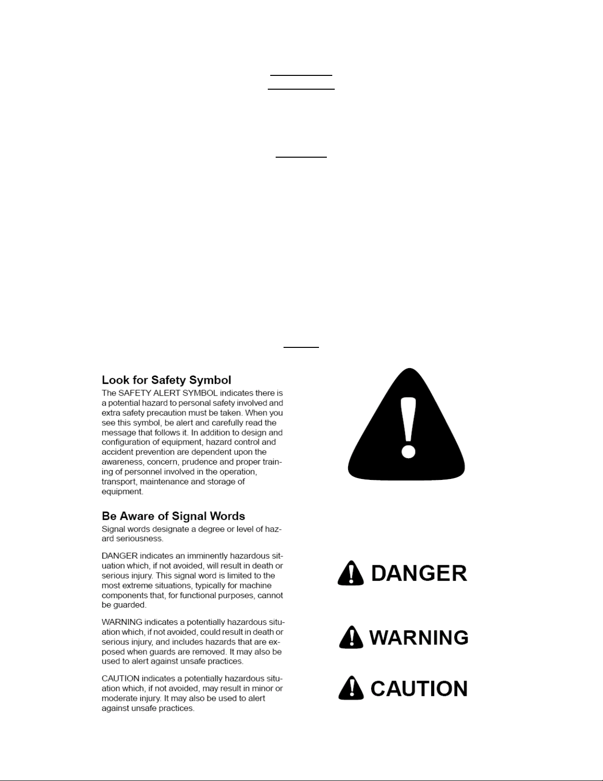
Safety
1-1
Page 3

OM17-pH Detector
Important! Read the following SAFETY PROCEDURES before operating the Veris system:
• Read and understand all instructions on safety decals
• Pinch point hazard: to prevent injury, stand clear when raising or lowering any part of the Veris
implement.
• Install all transport locks before transporting or working underneath.
• Detach and store implements in an area where children normally do not play. Secure implement
by using blocks and supports.
• Read Operations Manual before operating machine
• Review safety instructions with operators before operating machine and at least annually
• Riders obstruct the operator’s view. They could be struck by foreign objects or thrown from the
machine.
• Never allow children to operate equipment.
• To prevent possible electrical shock, or damage to the instrument, do not connect to any power
source greater than twelve (12) volts DC.
• Do not grease or oil implement while it is in operation.
• Probe edges are sharp. Be careful when working in this area.
• Disconnect battery ground cable (-) before servicing or adjusting electrical systems or before
welding on implement.
• Remove buildup of mud, oil or debris.
• Be very careful when mapping stubble fields with a gasoline engine vehicle. Be prepared if a fire
starts.
• Keep a first aid kit and fire extinguisher handy.
1-2
Page 4
OM17-pH Detector
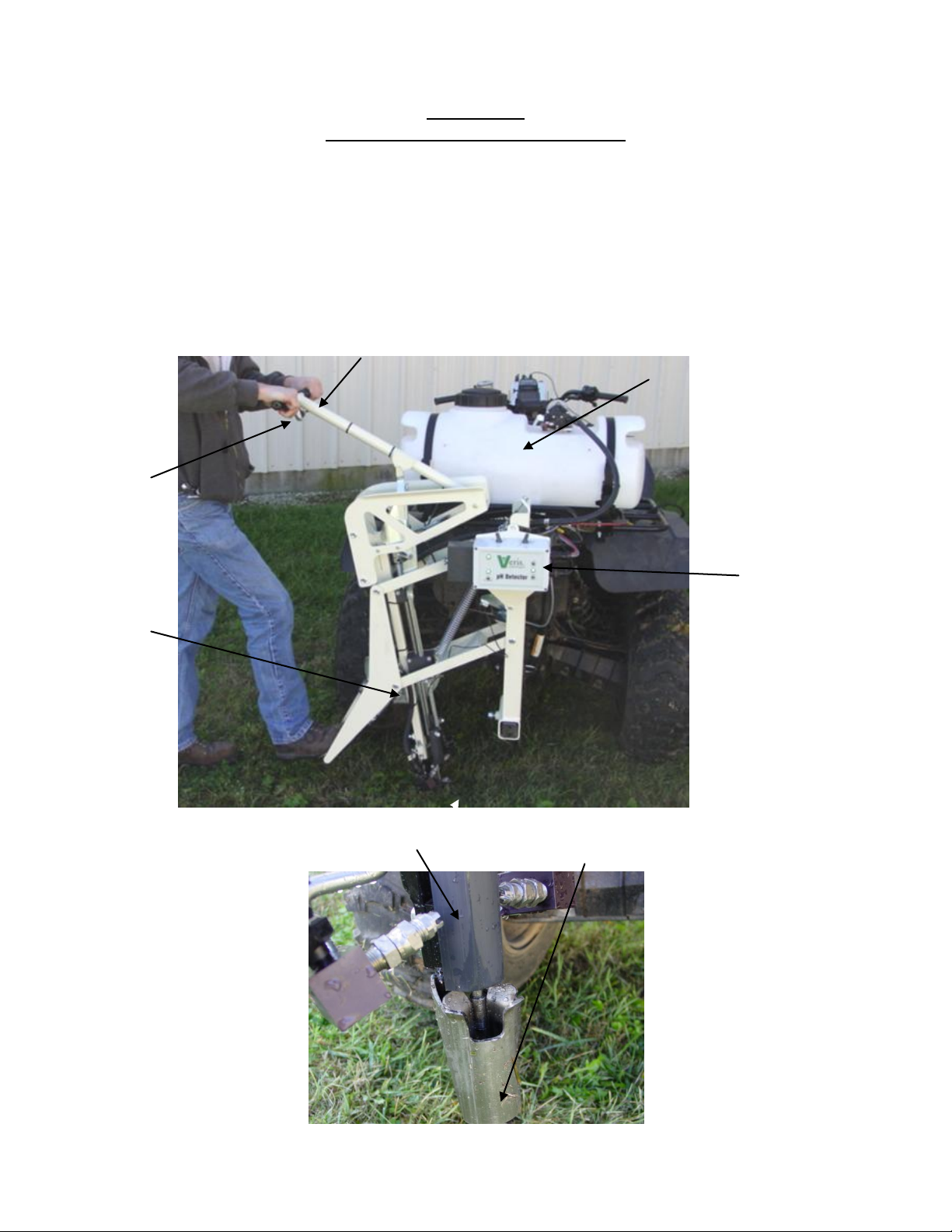
Hand
lever
Foot
lever
Wash
tank
External pH
controller
pH electrode
holder
Probe
chamber
Brake
mechanism
Brake
lever
Figure1
Figure 2
SECTION 2
pH Detector Assembly and Set-up
OVERVIEW:
The pH Detector collects a geo-referenced pH reading each time the pH electrode is inserted into
the soil. Here’s how it works: 1) the operator pushes the probe chamber into the soil with his foot,
2) then pushes down on the hand lever, activating a door that moves soil and creates an opening
for the measurement, 3) continues to push down on the hand lever to insert the pH electrode
holder, 4) the pH electrode measures the soil at the bottom of the opening, and when complete, 5)
the operator raises the probe handle, the electronics record the data and wash the electrode.
2-1
Page 5
OM17-pH Detector
Tools required for Assembly and Field Operation adjustments
-3/16” allen wrench
-7/16”, 1/2”, 3/8”, 9/16”, 3/4” wrenches and/or sockets
-pliers
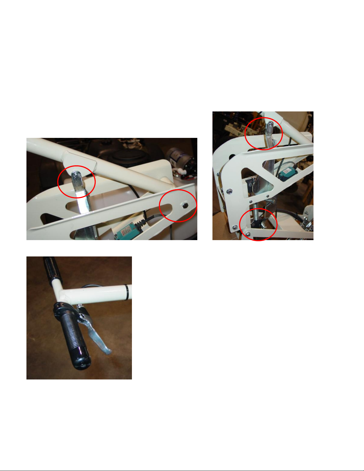
Handle installation: If probe handle was removed for shipping, reinstall by attaching pivot bolt, and
installing pins and cotter hairpins at top and bottom of rod actuator (Figure 3). Install brake lever
using 3/16” allen wrench, and zip-tie cable to handle (Figure 4).
Figure 3a and 3b
Figure 4
2-2
Page 6
OM17-pH Detector
tighten bolts after
unit has been
positioned and
stabilizer arms
attached
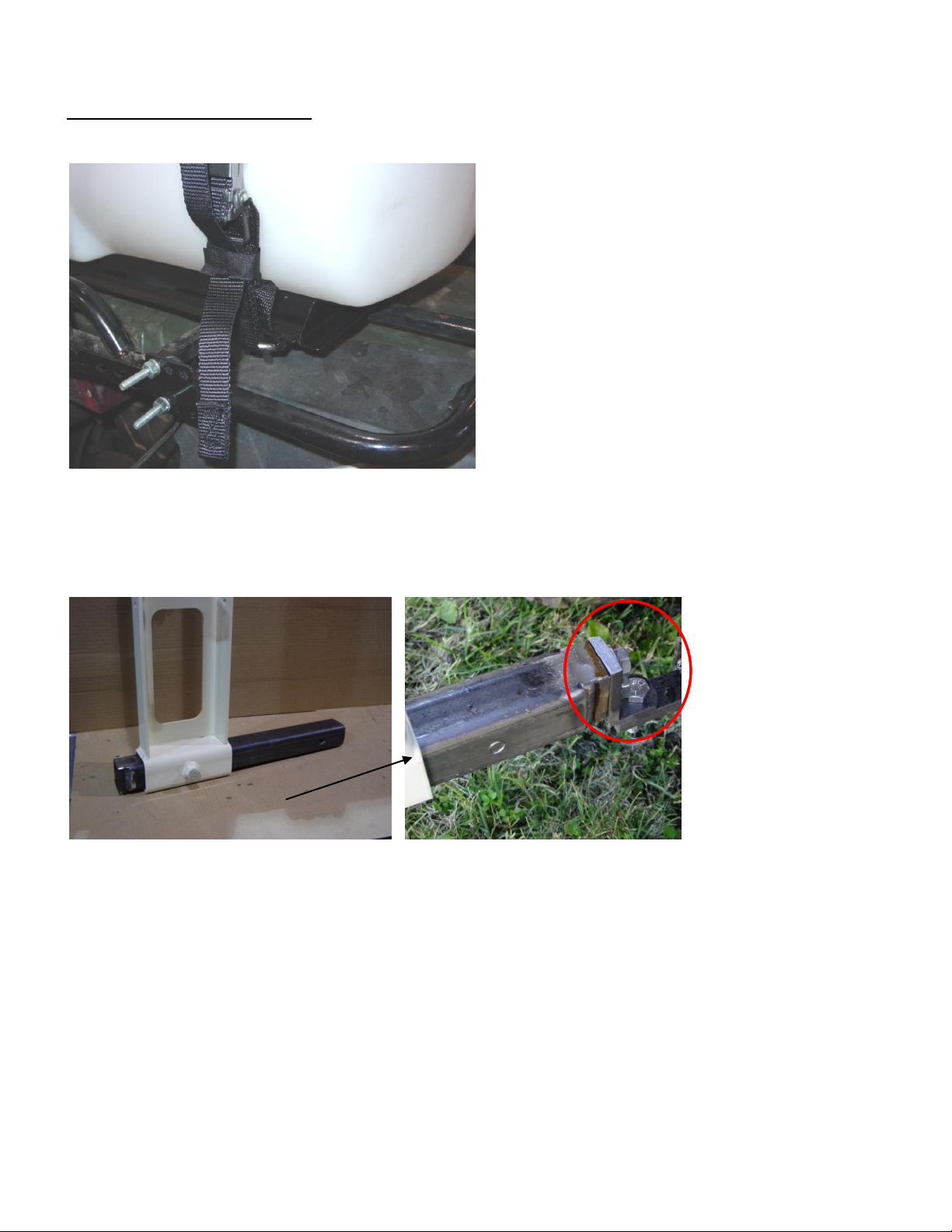
ATV hitch
Attaching pH Detector to ATV
Mount tank to rear rack of ATV using nylon straps or zip ties through holes in tank base(Figure 4).
Figure 5
Slide receiver hitch tubing inside lower main frame tube of pH Detector. If your ATV is equipped
with large receiver hitch, slide receiver hitch tubing directly into ATV receiver hitch and pin (Figure
5). If your ATV has a hole, or small receiver hitch, it will be necessary to use end of hitch tubing
with threaded holes. Attach L-bracket to these holes and bolt to ATV hitch hole (Figure 7).
Figure 6 Figure 7
Position pH Detector as close to rear of ATV as possible but don’t restrict probe movement. Attach
stabilizers to rear rack (Figure 8). These brackets can be bent to fit various racks. Once pH
Detector assembly is in position, tighten all bolts including hitch bracket bolts (Figures 5 and 6).
2-3
Page 7
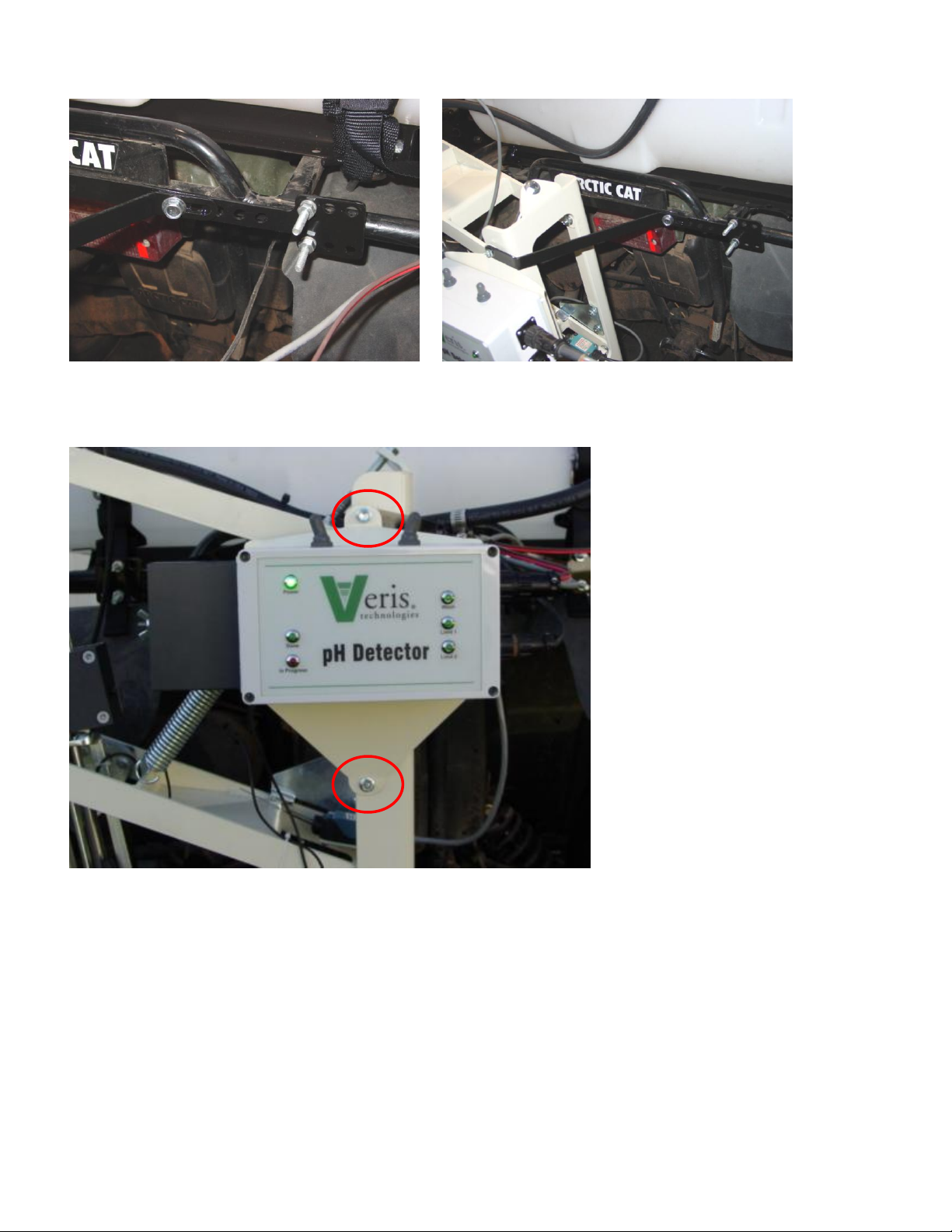
Figure 8a and 8b
Bolt pH controller to unit (Figure 9).
OM17-pH Detector
Figure 9
2-4
Page 8
Electronics Overview and Set-up
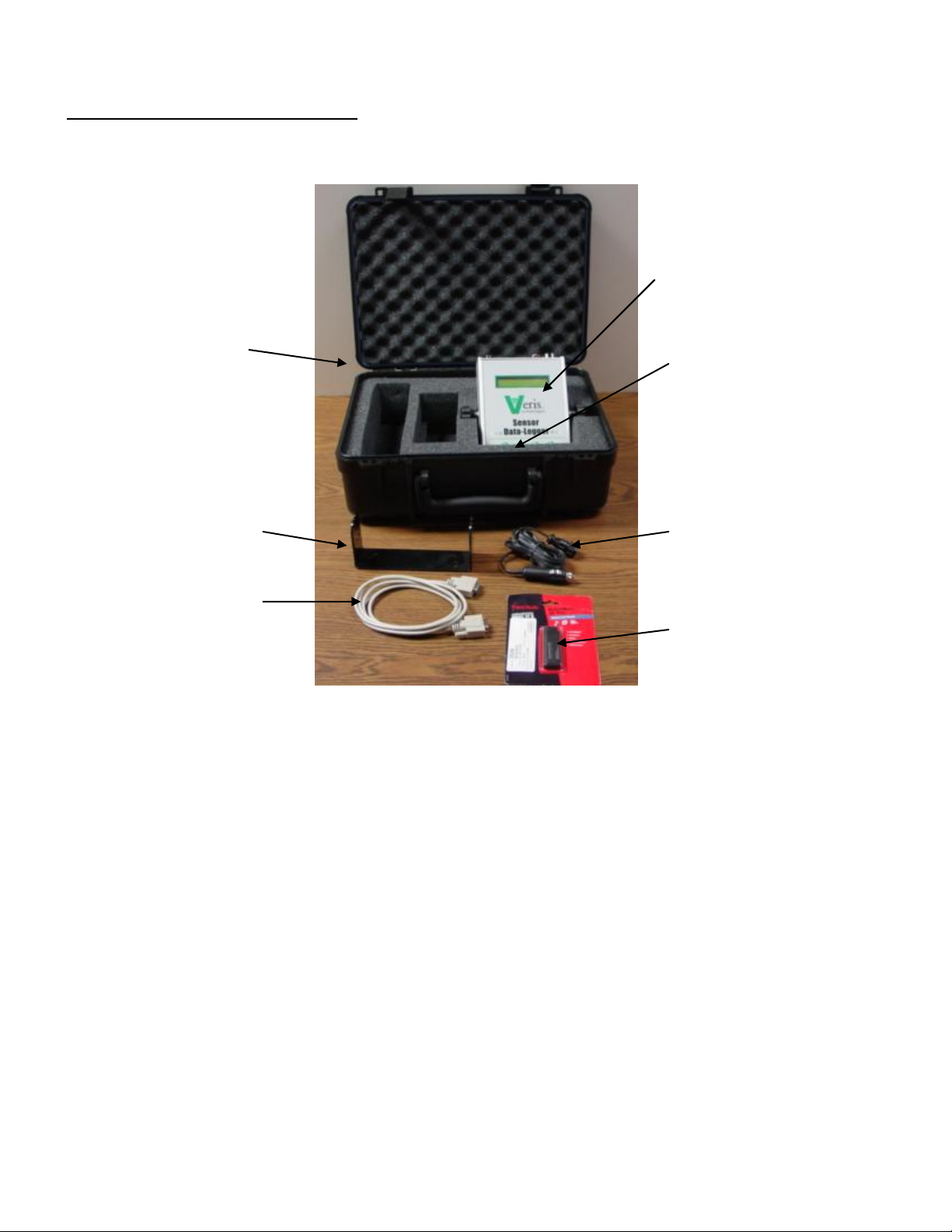
Sensor Data-Logger
Shipping/storage
case
Mounting bracket
Serial cable
Power cord
(cig. lighter end)
USB SD card reader
SD memory card
(shipped in DataLogger card slot)
The Veris Sensor Data-Logger kit includes the items shown in Figure 10.
OM17-pH Detector
Figure 10
Use protective shipping/storage case to protect electronics components whenever electronics are
shipped. Keep all diagnostics and operations manual with system when mapping.
The following electronic-related items are mounted on the pH Detector:
- pH controller
- 12 V power cable (from pH controller to battery)
- power distribution cable (from pH controller to pump and limit switch cables
- limit switches (2)
- wash pump
2-5
Page 9
OM17-pH Detector
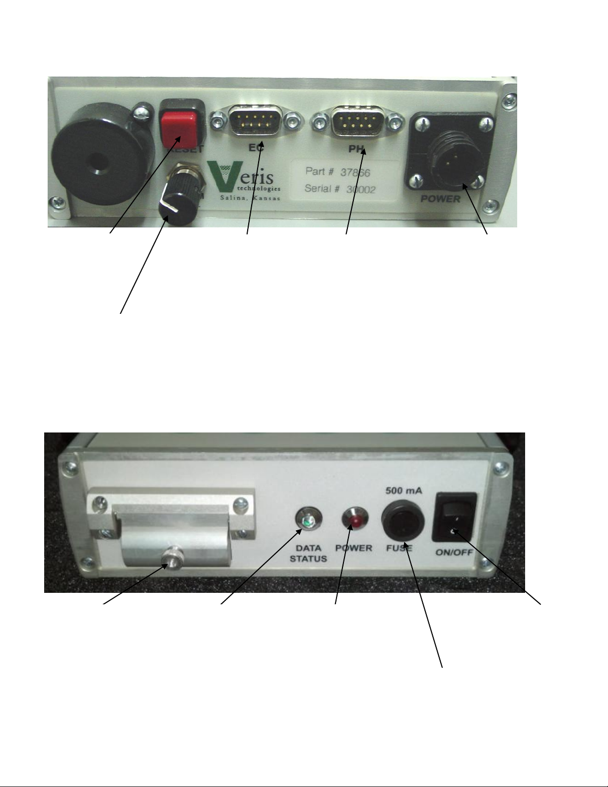
Power:
When lit, this red
LED indicates
Sensor DataLogger
is powered up.
On/Off:
Turns power to
Sensor DataLogger
on and off.
Memory Card slot:
SD memory storage
card must be
installed when
booting up, and at all
times data is being
collected.
pH:
Serial cable from
pH Controller
attaches here.
Reset
button:
Can be used
to reboot
DataLogger
Power port:
The Sensor Data-Logger is
shipped with an accessory
power cord. If an alternative
connection is desired, make
sure that the unit is properly
connected to a power
connection that is not
controlled by the ignition
switch. If connecting directly to
the battery, we suggest a 3-
amp in-line fuse is installed
between the battery and the
instrument.
Alarm Vol:
Used to adjust
volume of auditory
alarm
GPS input:
Connect GPS cable here. It
is designed to accept GPS
input in NMEA 0183 format
via an RS232 connector.
(GPS must send GGA and
either VTG or RMC strings at
a 1hz rate, at 4800 baud, 8
data bits, 1 stop bit, no
parity.)
Data Status:
When lit, this green
LED indicates data
is being recorded to
memory card. If not
lit, EC values are
negative or GPS
signal not received.
Fuse:
This allows the fuse to be
replaced, with a 500mA
Fastblow fuse, if blown.
Figure 11 DataLogger (rear)
Figure 12 Data-Logger (front)
2-6
Page 10

OM17-pH Detector
Important – Do not allow moisture to enter the Sensor Data-Logger, and do not pass strong
magnets near the unit.
Mount instrument in a location that is as free as possible from vibration and electrical interference.
Use adjustable mounting brackets to position electronics for optimal visibility.
Figure 13
Attach 12 volt leads to battery, making sure not to reverse polarity. Route wires under tank and
seat but do not allow them to be pinched. Attach main power amp and power distribution cables
connector to pH controller.
Figure 14
Attach the serial communication cable from external pH controller to the pH port on back of
DataLogger.
2-7
Page 11

OM17-pH Detector
Power switch
Manual
wash switch
Power LED
Wash LED
Done LED
(measurement
complete)
In Progress LED
(measurement
underway)
Lower limit
switch (#1)
LED
Upper limit
switch (#2)
LED
limit switches:
upper (#2)
lower (#1)
SECTION 3
Field Operations
Testing functions:
Turn external controller power switch on, and check operation using status LED’s. Power light
should light, wash LED should light when wash pump switch is activated, and limit switch LED’s
should light when they are deployed. (In order to active the lower switch (#1), probe must be in
soil.)
Figure 2a and 2b
Figure 1
3-1
Page 12

OM17-pH Detector
set screws
Quick
coupler
-Flush and fill tanks with tap water; clean any foreign matter out of tank using clean-out cap. Make
sure inlet is in sump (Figure 3), and strainer is attached to end of line (Figure 4).
Figure 3 Figure 4
Pump priming: In order to prime the pumps, loosen quick coupler and operate pump until water
flows (Figure 6).
Wash adjustment: This was set at the factory but may have slipped during shipping. Wash
brackets should be opposite each other, with jets as close as possible to electrode holder, and still
allow electrode holder movement. Jets should be 1/4” (6 mm) below electrodes. When wash jets
are properly aligned, overspray is minimized and water bubbles out top of empty electrode holder
as shown in Figure 5. To adjust wash jets, use 3/16” allen wrench to loosen set screws holding
wash jet blocks and rods (Figure 6).
Figure 5 Figure 6
3-2
Page 13

OM17-pH Detector
Connector
cover
Insert pH electrode into electrode holder. Finger-tighten plastic screw as tightly as possible by
hand. If a wrench is used, be careful not to over-tighten as damage to the electrode may occur
.
Figure 7
Route electrode cables away from sampling mechanisms to prevent damage. Lower probe to
maximum depth and tie strap cable as shown in Figure 8. Do not tighten zip ties until probe has
been moved full stroke to make sure wire slack is in correct area. Extra cable length should be
outside of sampling mechanism, below pH controller (Figure 9).
Figure 8 Figure 9
Install cover on external controller to keep moisture out of BNC and serial connector. When
installing cover, route electrode wire under box; center box on white pad, and tighten wingnut
finger tight. Keep cover installed even when electrode is removed.
3-3
Page 14

OM17-pH Detector
Sensor DataLogger display
Here are the display readings that you will see when operating the Sensor DataLogger:
Starting up…
Figure 10
The unit is ready to operate. The DataLogger is informing you of the firmware version its
programmable interface chip (PIC) contains.
Press any of the four keys, and the next screen will appear:
Figure 11
Press 2 and enter Setup menu. (Press 4 to Exit this window).
Figure 12
Press 1 to calibrate ion-selective (ISE) pH electrode.
Calibrating pH electrodes
Enter menu option 1) Calibration.
Figure 13
The instrument will prompt for the electrode to be inserted into pH buffer 4 solution; Slide cup with
pH 4 buffer solution onto electrode holder, or remove electrode from holder for calibration. Press 1
to continue with calibration or 2 to exit. Tips: Don’t overfill solution. Cup only needs enough
solution to immerse electrode tip and face. Don’t reuse solutions.
3-4
Page 15

OM17-pH Detector
Figure 14
Figure 15
The instrument will read the electrodes for 10 seconds, displaying the output (as it counts
seconds):
Figure 16
After 10 seconds, the instrument will display the final pH reading and offer the options to 1) Accept
pH 4 buffer readings; 2) Redo pH 4 buffer readings; or 3) Exit pH electrode calibration. If the
readings are satisfactory, press 1; if the readings are suspect, press 2 to return to re-do pH 4.
Figure 17
After accepting the pH 4 buffer readings, the Instrument will prompt for the electrode to be inserted
into pH 7 buffer solution. Remove the pH 4 buffer solution cup from the electrode holder. Rinse
the electrodes, electrode holder, and solution cup using the manual wash for at least 10 seconds.
Slide the pH buffer 7 solution cup onto the electrode holder.
On the DataLogger, press 1 to continue with calibration. The DataLogger will read the electrodes
for 10 seconds, displaying the output. After 10 seconds, the instrument will display the final pH
reading and offer the options to 1) Accept pH 7 buffer readings; 2) Redo pH buffer 7 readings; or 3)
Exit pH electrode calibration. If the readings are satisfactory, log pH 7 reading and press 1; if the
readings are suspect, press 2 to return to pH 7 calibration step.
3-5
Page 16

OM17-pH Detector
After accepting the pH 7 buffer readings, the electronics firmware will determine if the electrode’s
response is sufficient to provide suitable readings. A score is displayed for the electrode; the
acceptable score range is between 75 and 102. If electrode is within this range, the instrument will
display the following screen:
Figure 18
If an ‘X’ is displayed beside the electrode’s score, this indicates that the electrode did not perform
well enough for continued reliable use. No calibration settings are changed if calibration is
unsuccessful. The electrode should be removed and either cleaned or replaced and the calibration
procedure repeated.
Figure 19
After calibration is complete, you will have the option to use the calibrated readings or reset to the
ideal settings. Tip: many operators use the ideal settings rather than calibration settings. One
reason is this enables readings from one day to be compared to another. It is still important to
perform the calibration step at least daily, even if ideal settings are used. The calibration process
is important to test electrode quality.
If electrode doesn’t calibrate, check for film that develops on antimony tip after long storage
periods; sand lightly with 80 grit sandpaper or emery cloth.
• Antimony is harmful if ingested into your skin, mouth, or lungs
-Do not touch antimony electrode tip
-Do not ingest antimony material when sanding tip
3-6
Page 17

OM17-pH Detector
pH Controller Set-up
After calibration, you may wish to change the pH Controller default parameters. Press 2 and enter
Setup menu. (Press 4 to Exit this window).
Figure 120
Figure 21
Maximum log time is the longest time in seconds the pH controller will wait for the pH readings to
settle. The controller usually cycles before this maximum time is reached. The minimum setting
for the maximum log time is 20 seconds. (Tip: use 20 seconds unless there is a special reason to
allow a longer wait time) Press 1 or 2 to adjust the sample time, press 3 to continue to the next
screen.
pH Data Recording
Figure 22
From the screen above, press the #1 key and this screen appears.
Figure 23
Select #2 pH to collect pH data. #4 returns you to the initial start-up screen. Pressing #2 brings up
the next screen:
3-7
Page 18

OM17-pH Detector
Figure 24
The DataLogger is displaying the map file number it is creating, in case you want to record it along
with any other information about the field. Press any key to begin new map file. After starting the
file, pressing the #4 key will stop the file. If DataLogger freezes at the screen shown in Figure 23 or
Figure 24, check formatting of SD card—must be FAT format.
USING A VERIS SD CARD IN OTHER DEVICES CAN CAUSE FILE CORRUPTION.
If memory card was not inserted during boot-up, the following screen will appear:
Figure 25
Install card and re-start DataLogger. NEVER REMOVE CARD WHILE LOGGING DATA.
Figure 26
The display is showing the pH value from the pH electrode, the status of the sampling mechanism
(raised/neutral), and whether you have GPS or DGPS (differentially corrected) signal. At any time
during the mapping process, you can press the 4 key to stop the file. If you create more than one
file from the same field, you can bring the files into a spreadsheet program and combine them prior
to mapping.
3-8
Page 19

OM17-pH Detector
Probe Operations
Release the brake and step on the foot lever to insert the probe chamber into the soil (Figure 27).
This movement will activate the upper limit switch to initiate the electronic process, and a brief
wash burst will occur.
Figure 27a and 27b
Once the probe chamber is in the soil, insert the electrode holder by continuing to lower the
handle. In tight soil, it may be necessary to assist door opening with hand lever (Figure 28). The
software requires full electrode holder insertion indicated by the lower proximity switch in order to
begin logging. Release brake lever when electrode holder is completely inserted into probe
chamber.
Figure 28a and 28b
After the probe has been inserted and while the electrode is being held against the soil, the status
text will change to the following:
3-9
Page 20

OM17-pH Detector
Figure 29
Allow the sampler to remain in the soil while the readings settle, as indicated by the In Progress
red LED (Figure 30). When the Done green LED lights, the measurement is complete (Figure 31).
The pH readings on the display show what the electrode is reading at every second. The minimum
recording time is 7 seconds; the maximum time is determined in the pH settings menu. The pH
value that is recorded is the final values at the end of the logging duration. The final pH value is
logged along with the DGPS position where the sample was collected. When the Ready green
LED lights, release the brake and raise the probe chamber out of the soil and the electrode holder
out of the probe chamber. A spring-loaded pin will hold the probe in the top position for automated
electrode cleaning. DO NOT MOVE VEHICLE WHEN PROBE IS IN SOIL.
Figure 30 Figure 31
If the electrodes take longer than 10 seconds to settle, a warning will appear by the readings that
indicates the number of seconds the reading has required (Figure 32). When the maximum log
time is reached, a T will appear indicating that the measurement has ‘timed out’, and the unit
initiates a new sample cycle (refer to pH Controller settings for adjusting the log time).
Figure 32
This time warning is to let the operator know that a measurement cycle is requiring excessive time.
While an occasional cycle may exhibit this warning. see the troubleshooting section if this occurs
frequently.
3-10
Page 21

OM17-pH Detector
At any time during the mapping process, you can press the #4 key to stop the file. If you create
more than one file from the same field, you can bring the files into a spreadsheet program or GIS
and combine for whole field map display.
After #4 key is pressed during Data Acquisition, the following screen will be displayed: (if data
was collected during Data Acquisition)
Figure 33
DATA IS ONLY STORED ON THE SD CARD. NO INTERNAL FILES ARE CREATED.
If no data was logged during Data Acquisition, the following screen will be displayed:
Figure 34
Data Files
The DataLogger records four files for each data collection:
1. VPHFxxx.dat: your data file
2. VPHLxxx.dat: all logged soil data in millivolts
3. VPHWxxx.dat: all logged wash data in millivolts
4. Verisxxx.INF: calibration information for this file
File format for VPHF files is as follows:
Col A:long. Col B: lat. Col. C pH Col. D elevation Col. E: sample #
Figure 35
3-11
Page 22

OM17-pH Detector
Data quality tips
As you collect pH data, monitor the performance of the system by observing the following:
-During ‘Cycling’ phase or during manual washing, does pH electrode readings get close to the
wash water pH? If not, electrode may not be cleaning properly.
-During ‘Recording’ phase, does electrode reading move to expected soil pH level?
-Is there any residue in the cavity prepared by the probe chamber?
-Is depth of probe insertion consistent?
3-12
Page 23

Leave cover on whenever unit is
in operation or stored outdoors.
Do not allow moisture into BNC
or serial connections.
electrode body
reference junctions
electrode face
antimony measurement tip
pH Electrodes
OM17-pH Detector
SECTION 4
Maintenance and Service
Figure 1
• Antimony is harmful if ingested into your skin, mouth, or lungs
-Do not touch antimony electrode tip
-Do not ingest antimony material when sanding tip
-Always use proper soaker solution: Veris part #23395
-Keep moist; put in soaker solution if mapping (washing) is interrupted for one hour of more
-If soaker solutions is unavailable, use pH buffer 4; never soak in distilled or de-ionized water
-remove from holder and place in individual soaker bottles in freezing temperatures and when unit
will be idle for long periods
-keep cover over BNC ports on external controller whether electrodes are attached or unattached
-if film develops on antimony tip, sand lightly with 80 grit sandpaper or emery cloth.
Figure 2
4-1
Page 24

OM17-pH Detector
Clean filter at end of suction line
weekly.
Open up check diaphragms and
allow lines to clear.
Wash System
If wash water develops algae, flush and fill tanks with tap water; clean any algae or other foreign
matter out of tank. Clean filter at least once per week of operation.
Figure 3
Winterizing:
When temperatures are dipping below freezing, prevent freeze damage to the wash system as
follows: drain tank, open up check diaphragms and drain, and run pumps until empty. If unit is to
be left outside for long periods of time over winter, it is advisable to add RV antifreeze to tank and
run pumps for a couple of minutes to fill all lines with anti-freeze. Purge system of anti-freeze
before collecting any pH data.
Figure 4
4-2
Page 25

OM17-pH Detector
Door didn’t
close when
electrode
holder was
raised
Electrode
holder
hitting
door
In up
position,
lever
should be
in notch.
Adjustments/troubleshooting:
Electrode holder won’t go into soil:
1) If door is not completely open when electrode holder tries to enter, electrode breakage may
result (Figure 5). Raise electrode holder and see if door closes completely. If rock or other
obstruction is present, clear it and see if door closes properly.
Figure 5a Figure 5b
2) Verify that door hand lever hasn’t slipped. If door is closed but lever is not in notch, loosen
lever bolt and set screws, reposition lever to notch, and retighten bolt and set screws.
(Figure 6).
Figure 6a Figure 6b
4-3
Page 26

OM17-pH Detector
Hold top of rod
with adjustable
wrench and
tighten jam nut
with 1/2” wrench
limit switches:
upper (#2)
lower (#1)
3) Verify that bottom jam nut on pivot rod hasn’t slipped. If hand lever does not move door,
retightening pivot rod jam nut is required. Retighten by holding top of rod with adjustable
wrench and tightening jam nut on lower end of pivot rod (Figure 7).
Figure 7a Figure 7b
Limit switches aren’t working properly:
-activate manually to see if LED’s light; if LED’s do not light, check power and connections
-if LED’s light, but are reversed from Figure 8, disconnect weather-pack connectors and re-connect
to other switch.
Figure 8 Figure 8b
-If limit switch LED’s show switch is working, check adjustments: In raised position, lower switch
needs to be in activated position, as shown in Figure 9. To adjust, loosen bolt holding switch and
pivot to desire position.
4-4
Page 27

OM17-pH Detector
Figure 9
Upper switch needs to be in activated position only when electrode holder is fully inserted into the
probe chamber (Figure 10). To adjust activation bar, loosen bolt and slide to desired position
Figure10
4-5
Page 28

OM17-pH Detector
Tighten
adjustment bolt
to increase
spring tension
Excessive movement of assembly while driving: tighten up spring tension on main springs (Figure
11).
Figure 11
Probe doesn’t stay locked in up position for washing: tighten spring plunger to increase pressure
(Figure 12.)
Figure 12
4-6
Page 29

Lubrication
Weekly:
Apply dry powdered graphite to slides in wear blocks shown in Figure14.
OM17-pH Detector
Figure 14a Figure 14b
4-7
 Loading...