

Page 1

1
Operating Instructions
Mobile Sensor Platform
Table of Contents
General Information Section
P. 2 Warranty and Safety
P. 4 Instrument—installation and set-up
P. 5 File Management—data downloading and transfer
P. 7 GPS trouble-shooting
P. 8 Instrument firmware update procedure
Soil EC Surveyor
P. 10 Installation and set-up
P. 12 Field Operations
P. 15 Maintenance and Lubrication
P. 21 Troubleshooting
pH Manager
P. 22 Installation and set-up
P. 25 Field Operations
p. 27 Adjusting sampling depth
p. 28 Other adjustments
p. 30 pH electrode calibration
p. 33 Collecting pH data
p. 39 Clean-up
P. 40 Maintenance and Lubrication
P. 45 Troubleshooting
Veris Technologies
Pub. #OM MSP03-1
Page 2
Veris Technologies
2
Pub. #OM MSP03-1
VERIS Mobilized Sensor Platform (MSP)
(Software Version MSP 1.02a)
Warranty
Veris Technologies warrants this product to be free of defects in materials and workmanship for a
period of one (1) year from the date of delivery to the purchaser. Veris Technologies will repair or
replace any product returned to Salina, Kansas, which appears upon inspection to be defective in
materials or workmanship. Veris Technologies will have shall have no obligation under this warranty
for the cost of labor, down-time, transportation charges, or for the repair or replacement of any
product that has been misused, carelessly handled, modified, or altered.
ALL OTHER WARRANTIES OF ANY KIND, WHETHER EXPRESSED OR IMPLIED, INCLUDING
BUT NOT LIMITED TO ANY IMPLIED WARRANTY OF MERCHANTABILITY OR OF FITNESS FOR
A PARTICULAR PURPOSE AND ALL CLAIMS FOR CONSEQUENTIAL DAMAGES, ARE
SPECIFICALLY DISCLAIMED AND EXCLUDED.
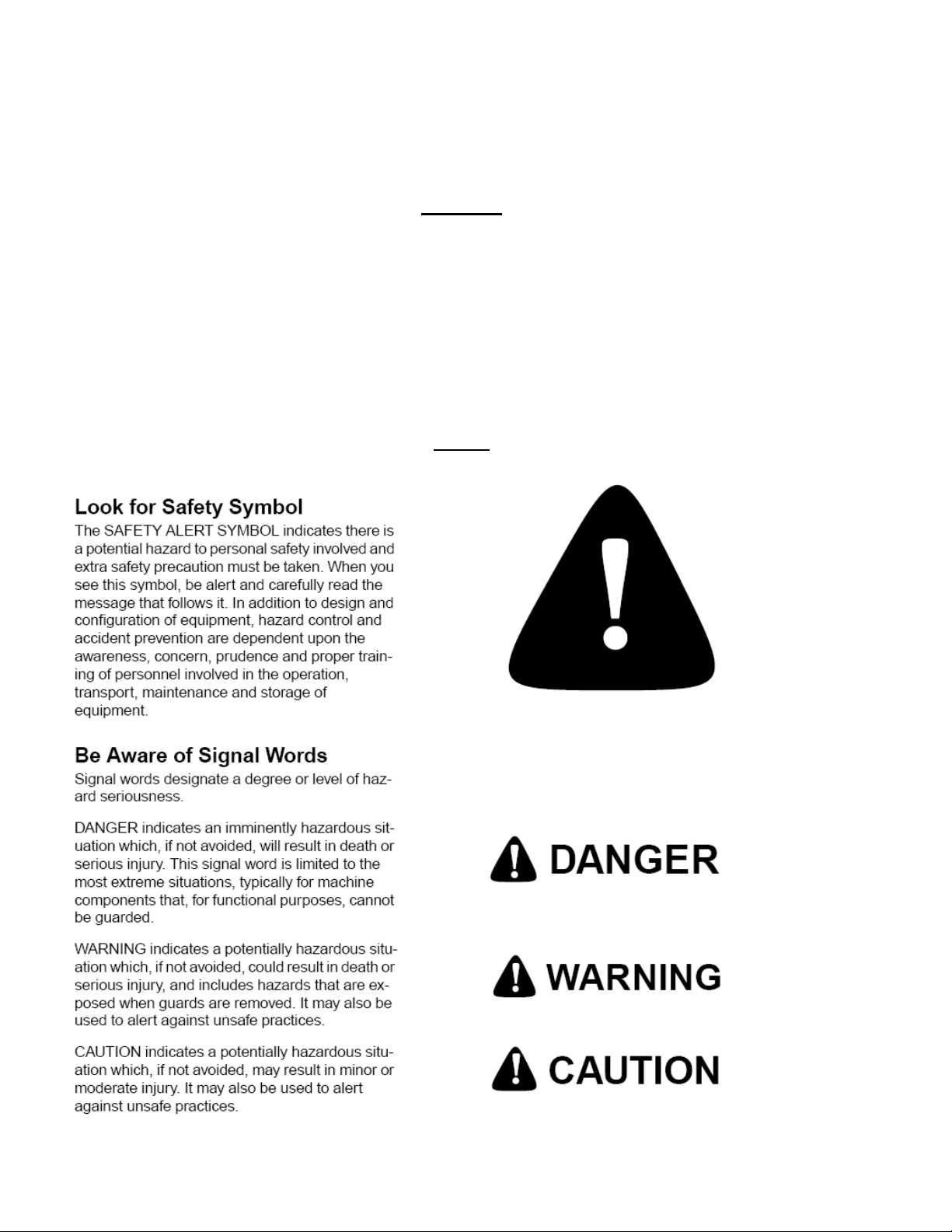
Safety
Page 3

Veris Technologies
3
Pub. #OM MSP03-1
Important! Read the following SAFETY PROCEDURES before operating the Veris MSP:
• Read and understand all instructions on safety decals
• Before filling tank with gasoline, let engine cool. Gas vapors can ignite and an explosion can occur.
• Escaping fluid under pressure can penetrate the skin causing serious injury. Avoid the hazard by
relieving pressure before disconnecting hydraulic lines. Use a piece of paper or card-board, NOT
BODY PARTS, to check for suspected leaks.
• Wear protective gloves and safety glasses or goggles when working with hydraulic and highpressure wash systems.
• If an accident occurs, see a doctor immediately. Any fluid injected into the skin must be surgically
removed within a few hours or gangrene may result.
• Pinch point hazard: to prevent injury, stand clear when raising or lowering any part of the Veris
MSP. Disengage automatic cycling function before working around unit.
• Install all transport locks before transporting or working underneath.
• Detach and store implements in an area where children normally do not play. Secure implement by
using blocks and supports.
• Read Operations Manual before operating machine
• Review safety instructions with operators before operating machine and at least annually
• Never stand on or use tire as a step
• Do not tow the implement on public roads without the optional light package, or without the proper
safety equipment and licensing as required by your State Department of Transportation. Always use
safety chain.
• Riders obstruct the operator’s view. They could be struck by foreign objects or thrown from the
machine.
• Never allow children to operate equipment.
• To prevent possible electrical shock, or damage to the instrument, do not connect to any power
source greater than twelve (12) volts DC.
• Do not grease or oil implement while it is in operation.
• Disk edges are sharp. Be careful when working in this area.
• Disconnect battery ground cable (-) before servicing or adjusting electrical systems or before
welding on implement.
• Remove buildup of mud, oil or debris.
• Be prepared if a fire starts.
• Keep a first aid kit and fire extinguisher handy.
Page 4
4
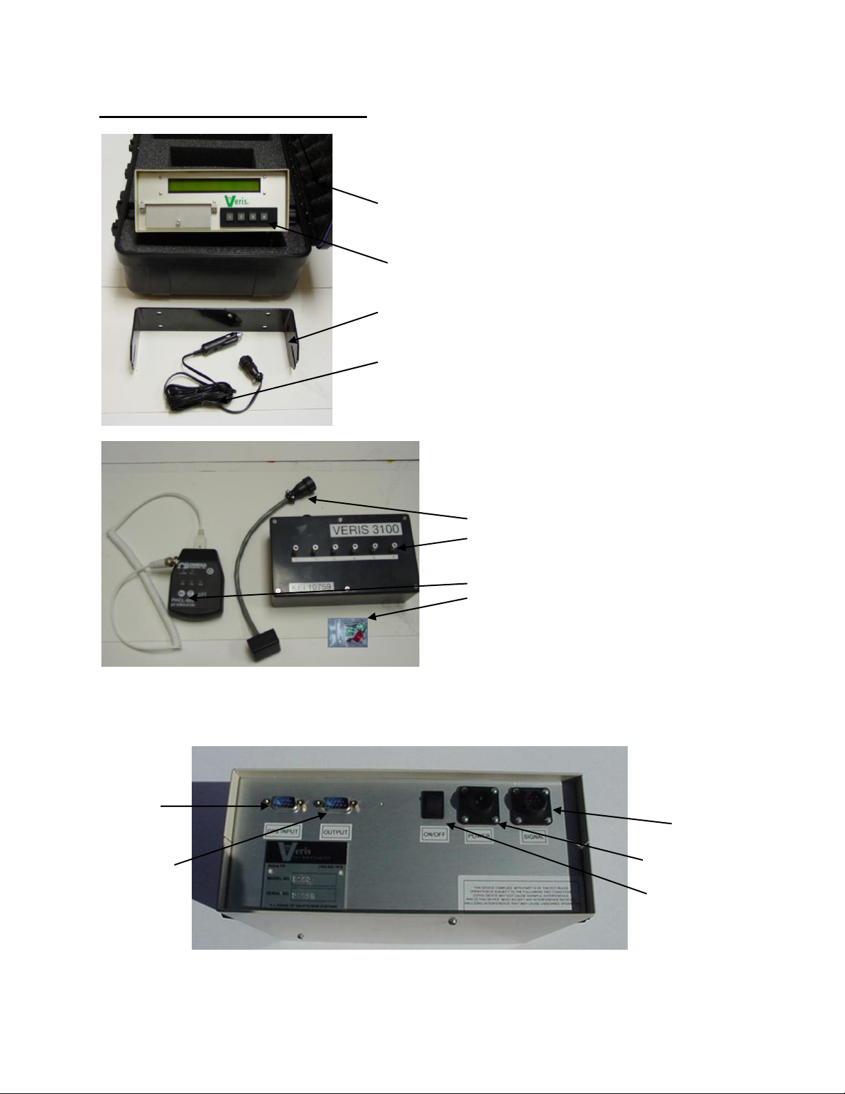
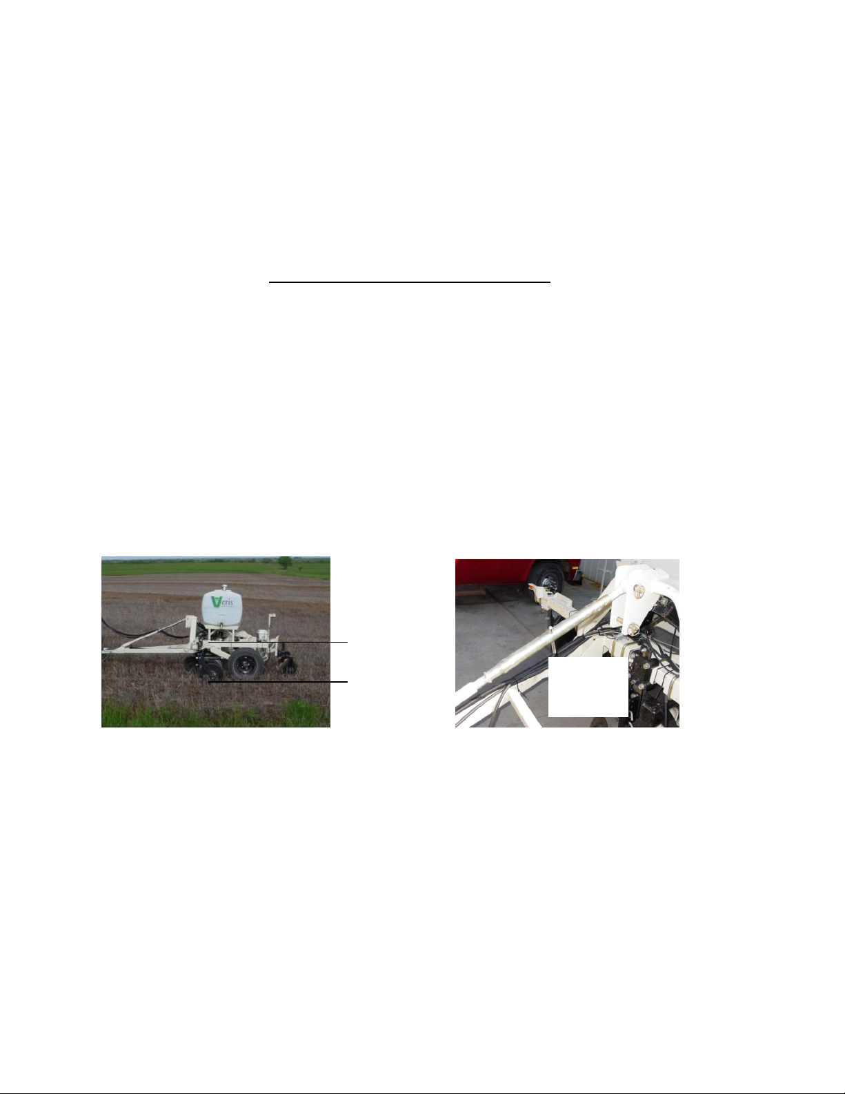
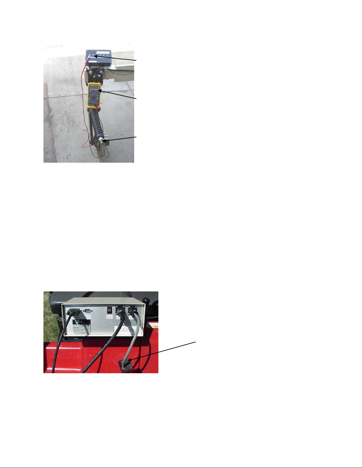
Instrument Installation and Set-up
Protective
case
EC and pH
Instrument
Mounting
Bracket
Power Cable
Trouble-shooting items:
Included with EC module:
EC signal test load
EC continuity test box
Included with pH module:
pH simulator
fuse kit
Keep these along with the
Operating Instructions with the
unit whenever collecting data.
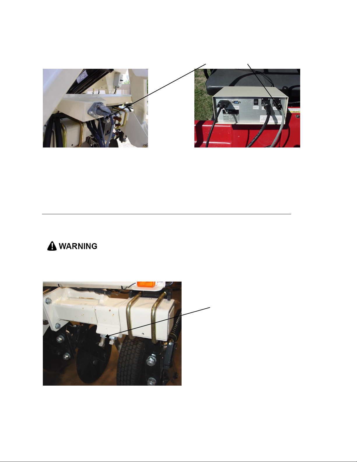
serial port for
GPS signal
cable
serial port for
pH signal
cable or file
transfer
power
switch
power cable
port
signal port for
E.C signal
cable or test
load
The Veris Instrument Kit includes the following items:
Veris Technologies
Pub. #OM MSP03-1
Mount instrument in a location that is as free as possible from dust, vibration, and electrical
interference. Display should be visible to operator and shielded from direct sunlight.
Below is a rear view of the instrument
Connect GPS cable to GPS INPUT serial port on back of instrument. The Veris instrument is
designed to accept GPS input in NMEA format via an RS232 connector. Note: GPS signals are
frequently affected by electrical interference from magneto electrical systems. If your vehicle uses a
Page 5
Veris Technologies
5
Pub. #OM MSP03-1
magneto, consider powering the Veris instrument with a 12-volt battery or converting to an alternator
system.
The Veris MSP is shipped with an accessory power plug. If an alternative connection is desired,
make sure that the unit is properly connected to a power connection that is not controlled by the
ignition switch. If connecting directly to the battery, we suggest a 3 amp. in-line fuse is installed
between the battery and the instrument. Important – Do not allow moisture to enter the
instrument, and do not pass strong magnets near the unit.
Note: This equipment has been tested and found to comply with the limits for a Class A digital
device, pursuant to Part 15 of the FCC rules. These limits are designed to provide reasonable
protection against harmful interference when the equipment is operated in a commercial environment.
This equipment generates, uses, and can radiate radio frequency energy and, if not installed and
used in accordance with the instruction manual, may cause harmful interference to radio
communications. Operation of this equipment in a residential area is likely to cause harmful
interference in which case the user will be required to correct the interference at their own expense.
Changes and modifications not expressly approved by Veris Technologies could void the user’s
authority to operate the Veris MSP.
File Management
Data is stored in the Veris instrument on a flash memory chip and simultaneously on a removable
CompactFlash (CF) card. The File Management option is used to re-copy data files from the
instrument’s flash memory to the CF card and to delete files from either the instrument or the CF
card.
Downloading Data
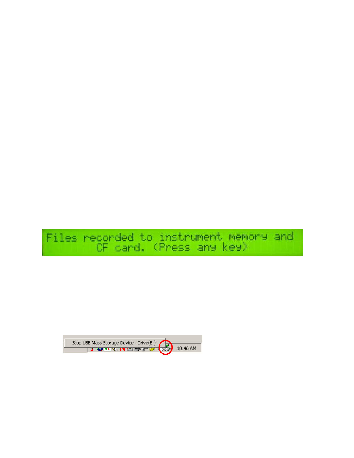
When you are ready to stop collecting data to the file, press 4.
The unit is telling you that you have finished creating files and that the files have been saved on both
the Instrument’s flash memory and the removable CF card You may shut the power off at this point.
Use the included USB CF card reader to transfer files from the CF card to your computer. Before
transferring files for the first time, follow the manufacturer’s directions for installing any necessary
drivers for the USB reader.
Follow these steps to transfer files from the CF card to your computer:
1) Shut off your instrument. Always turn the instrument off before removing the CF card.
2) Remove the CF card from the instrument and insert it into the USB reader.
3) Connect the USB reader to your computer.
4) Transfer the data files from the CF card to your computer using File Manager.
5) Left mouse click on the green arrow in your computer’s system tray and again on the button
“Stop USB Mass Storage Device”.
6) Click “OK” on the window that appears. It is now safe to remove the card reader from your
computer and re-insert it in to your instrument.
**NOTE: The instrument WILL NOT function without the CF card inserted. If the
instrument is turned on without the CF card inserted, the display will only show black bars
on the first line. If this occurs, shut down the instrument, insert the CF card, and restart
the Instrument.
**NOTE: DO NOT leave the CF card and USB card reader connected to your computer when
shutting down or restarting your computer.
Page 6

Veris Technologies
6
Long.
Lat.
E.C. Shallow
E.C. Deep
Elevation
-88.7579
43.49488
2.2
5.9
291.2
Long.
Lat.
Electrode 1 (mV)
Electrode 2 (mV)
Elevation
Speed
-88.7579
43.49488
-20
-25
291.2
4.5
Long.
Lat.
Electrode 1 (mV)
Electrode 2 (mV)
Controller state
-88.7579
43.49488
-20
-25
33
LONGITUDE
LATITUDE
pH
TIME
ALTITUDE
SPEED
Sample
Flag
-88.7579
43.49488
6.75
8.5
291.2
4.5 1
accepted
rejected
settling
range
difference
216 1 0 5
mean time
mean speed
6.8
5.1 pH1 mean
pH2 mean
7.00
7.00
pH1 SD
pH2 SD
0.002
0.000
pH1 start
pH1 end
7.00
7.00
pH2 start
pH2 end
7.00
7.00
Pub. #OM MSP03-1
About the Veris EC output file format
Veris EC data is output as a 5 column ASCII text file. Column A: longitude, B: latitude, C: EC Shallow
Array (mS/m), D: EC Deep Array (mS/m), E: DGPS elevation (meters):
About the Veris pH output file formats
3 files are created during pH data acquisition: one containing the raw millivolt readings of the
electrodes in soil (VPHL000.DAT), one containing the millivolt readings of the electrodes during the
wash sequence (VPHW000.DAT), and one containing the final settled smoothed soil pH readings
(VPHE000.DAT). A formatting example of each file type follows:
Raw soil millivolts (VPHLXXX.DAT):
Wash sequence millivolts (VPHWXXX.DAT):
Extracted soil pH (VPHEXXX.DAT):
The extracted file also contains 5 columns of file statistics at its end offset from the normal data:
The extracted pH file contains the coordinates of the reading’s location, the settled, averaged pH
reading, the time the reading took to settle, the readings’ elevation, the speed the vehicle was moving
at the time the sample was taken, the reading’s sequence number, and the reading’s flag sequence
number if the point was flagged during Data Acquisition. The statistics at the end of the file break
down how many points were considered “good” by the extraction routine and how many were rejected
and the reason for rejection. A point can be rejected for 3 reasons: 1. The readings did not settle in
the maximum time allowed; 2. The readings were outside of a reasonable pH range (less than 3.5 or
greater than 9.5); or 3. There was more than a 0.5 pH difference between the electrodes.
Downloading/deleting old files
This section deals with how to download and delete old files. Veris Technologies recommends that
you do not delete any files until they have been saved to a hard disk drive and properly backed up.
Once you have done this, it’s a good idea to delete the files from the Veris instrument. This will
ensure that you have enough available memory to store the new map files you are creating. It is also
recommended that you delete any files that you make while setting up or checking out the system,
especially files with no data on them, such as those you make while testing the DGPS signal
reception.
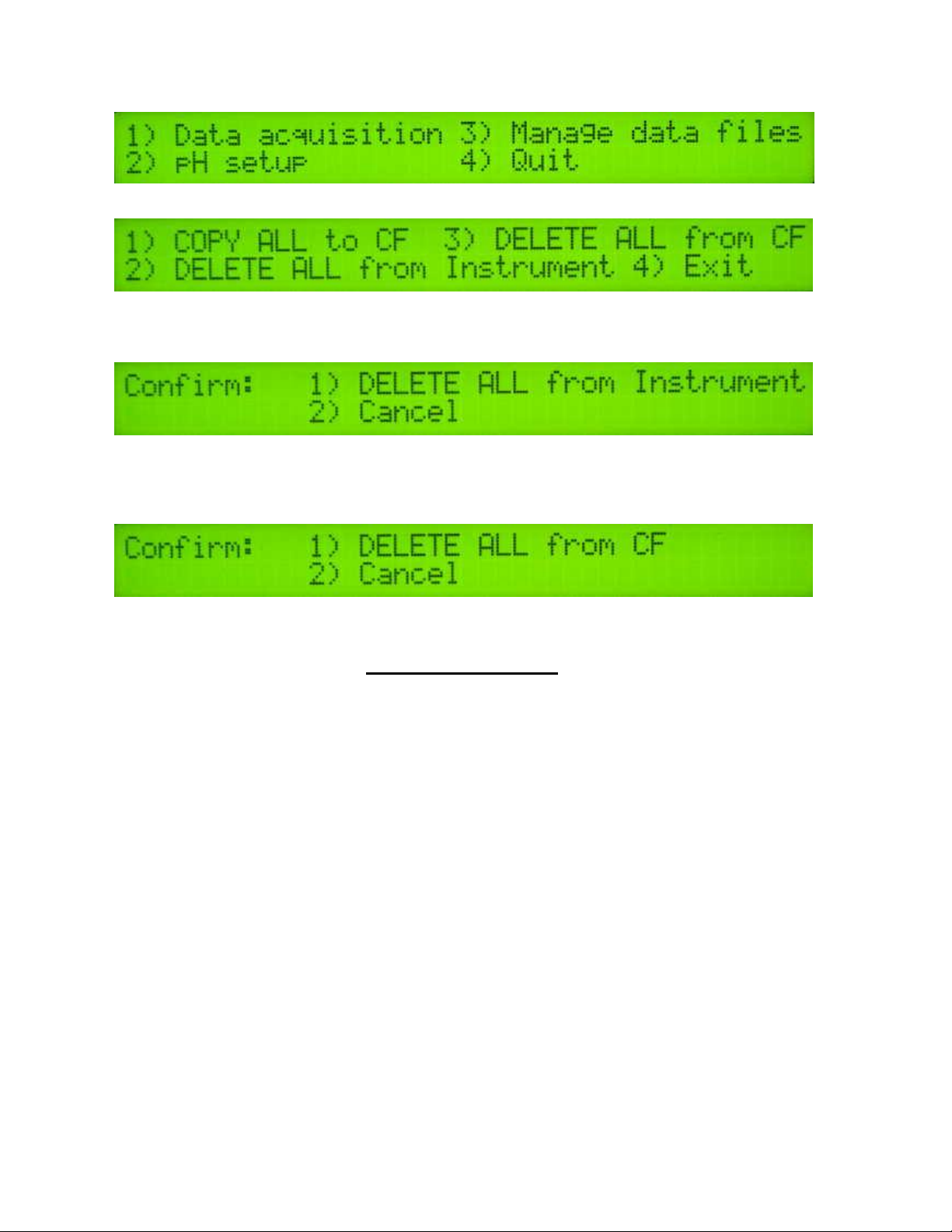
At the display:
Page 7
Veris Technologies
7
Pub. #OM MSP03-1
This is the second window you will see after powering up the unit. Select 3 to download or delete
files that are stored on the Instrument or the removable CF card.
Select option 1 to copy all data files stored in the Instrument’s memory to the removable CF card.
The instrument will proceed to copy every data file stored on the instrument to the CF card.
Select option 2 to delete ALL data files from the Instrument’s memory. The next window displayed
will be a confirmation screen:
Make sure all data files are backed up to a secure location (i.e. desktop or laptop PC) before pressing
1 to delete ALL files from the Instrument.
Select option 3 from the previous menu to delete ALL files from the removable CF card. The next
window displayed will be a confirmation screen:
Make sure all data files are backed up to a secure location (i.e. desktop or laptop PC) before pressing
1 to delete ALL files from the CF card.
GPS Troubleshooting
This is a problem-solving guide for the user who is not able to obtain a position from the GPS when it
is connected to the Veris MSP instrument. Note that when the system is working properly, the DGPS
indicator should appear on the left-hand side of the instrument display and the instrument should not
beep when the vehicle is in motion (provided the conductivity readings are positive).
GPS Settings
1. Make sure that the GPS is plugged into the proper DB-9 input. Looking at the back of the
instrument, the GPS should be plugged into the leftmost input port. A null modem adapter should
not be used.
2. Make sure that the GPS has power and has been turned on long enough to start outputting data.
Some units may require a couple minutes to start while others may require much longer.
3. Make sure the GPS output is at 4800 baud, 8 data bits, no parity and 1 stop bit. (note: set parity
to “None”, not “zero”)
4. Make sure the GPS is set to output NMEA-0183 messages that include the GGA and VTG or
RMC string. The GGA string provides the position and fix quality while the VTG or RMC string
provides the speed. Make sure the update rate is set at 1 Hz.
5. If your settings appear correct, but the position still does not appear on the Veris instrument, use
a laptop to monitor the GPS signal to verify its integrity. If the signal appears properly on a
laptop, it should work on the instrument as well.
To do this,
a) plug the GPS output into the laptop serial input and then start the “HyperTerminal” program
under “Accessories” in Windows.
b) click on the icon called “hypertrm.exe” to establish a connection.
c) Type in “gps” when the program prompts you for the name of your connection and then hit
“OK”.
Page 8
Veris Technologies
8
Pub. #OM MSP03-1
d) The program will then ask you for a phone number. Instead of entering a phone number,
specify the proper serial port number. For example, if Com 1 of the laptop is being used,
specify “Direct to Com 1” under “connect using:” at the bottom of the entry area.
e) HyperTerminal will then display a configuration menu where you can specify 4800 bits per
second, 8 data bits, no parity, 1 stop bit and no flow control.
At this point, upon clicking ok, legible strings of GPS data should begin appearing on the laptop
screen. Here’s an example of a typical set of strings:
$GPGGA,191528.00,3851.0333,N,09737.2342,W,2,08,1.3,372.7,M,27.3,M,10.0,0100*69
$GPGSA,A,3,09,23,21,17,08,01,03,29,,,,,2.6,1.3,2.3*39
$GPRMC,191528.00,A,3851.0333,N,09737.2342,W,0.1,0.0,090998,6.3,E*48
If GPS data doesn’t appear, recheck the port and configuration settings to make sure they are
correct. If the data won’t appear correctly in HyperTerminal, consult your GPS supplier to see what
adjustments (connectors or software) are necessary to bring the signal into a computer. On the other
hand, if the signal appears correctly on HyperTerminal and it shows that the required strings are
being output, retry the unit with the Veris instrument. If it still doesn’t work, please call Veris at 785825-1978 to see how we can help solve the problem.
Updating Instrument Firmware
Steps for updating the Veris Instrument firmware:
1. Shut Instrument off and remove CompactFlash card. Always turn the
instrument off before removing the CF card.
2. Insert CompactFlash card into CompactFlash card USB reader.
3. Plug USB reader into computer.
4. Copy the file VERIS.EXE from your computer to the CompactFlash card.
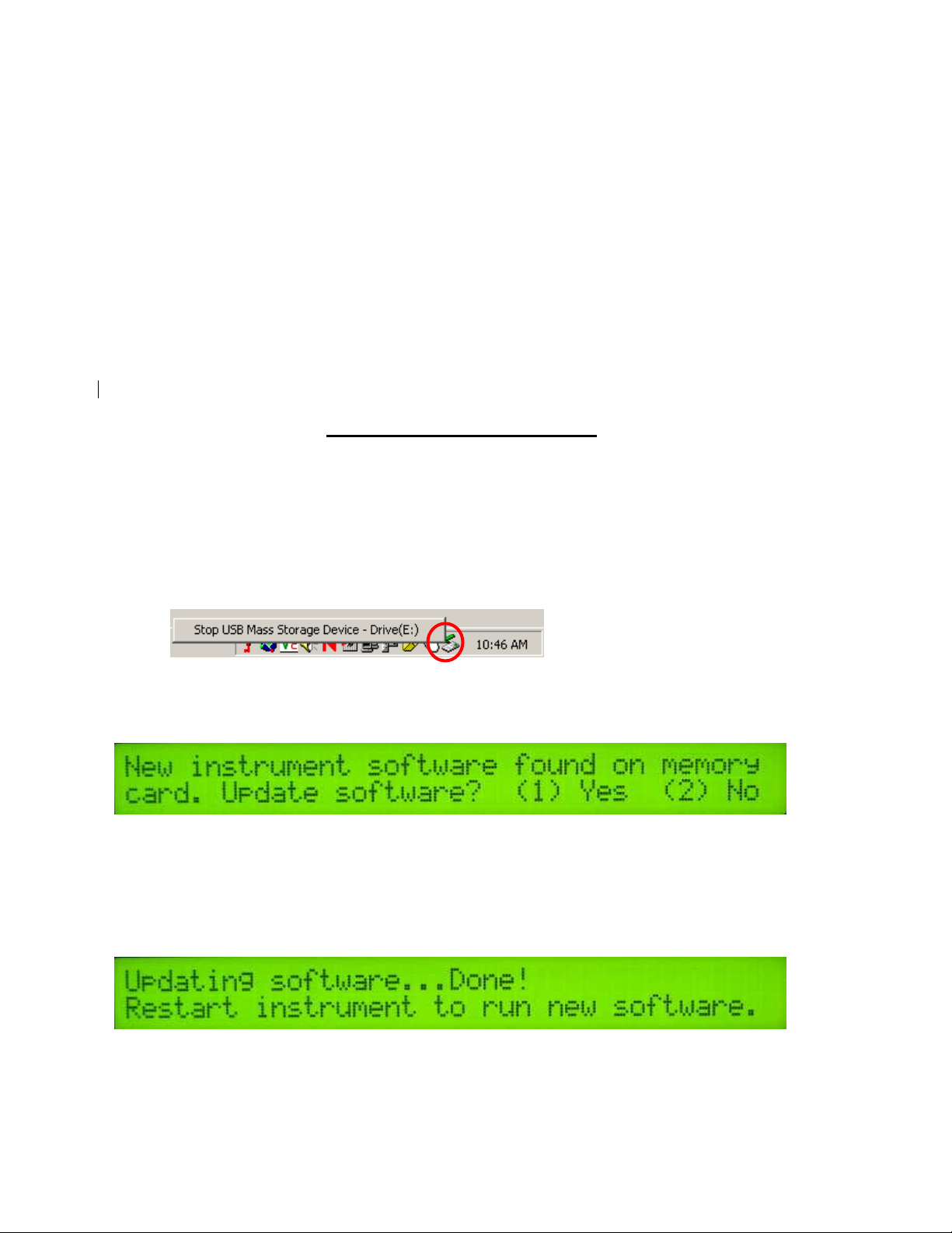
5. Left mouse click on the green arrow in your computer’s system tray and again
on the button “Stop USB Mass Storage Device”.
6. Click “OK” on the window that appears. It is now safe to remove the card
reader from your computer.
7. Insert CompactFlash card into the Instrument and restart the Instrument.
During bootup, the following screen will appear:
**NOTE: The instrument WILL NOT function without the CF card inserted. If the
instrument is turned on without the CF card inserted, the display will only show
black bars on the first line. If this occurs, shut down the instrument, insert the CF
card, and restart the Instrument.
8. Press (1) to continue with the update procedure. Press 2 to continue to the
main title screen.
9. After the Instrument is done updating, the following screen will appear:
10. Restart the Instrument. The new firmware will be running. During the update
process, the VERIS.EXE file is deleted from the CompactFlash card so these
screens will not be seen when the Instrument restarts.
Page 9
Veris Technologies
9
Pub. #OM MSP03-1
Running Utility Files
Utility files can be run from the CompactFlash card to perform various tasks. Here
are the general instructions for running utility files:
1. Shut Instrument off and remove CompactFlash card. Always turn the
instrument off before removing the CF card.
2. Insert CompactFlash card into CompactFlash card USB reader.
3. Plug USB reader into computer.
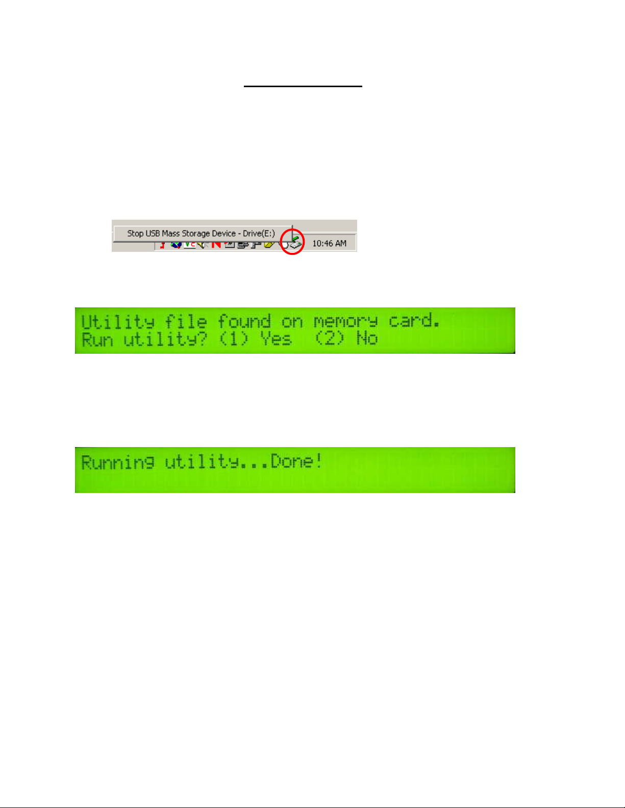
4. Copy the file VERIS.BAT from your computer to the CompactFlash card.
5. Left mouse click on the green arrow in your computer’s system tray and again
on the button “Stop USB Mass Storage Device”.
6. Click “OK” on the window that appears. It is now safe to remove the card
reader from your computer.
7. Insert CompactFlash card into the Instrument and restart the Instrument.
During bootup, the following screen will appear:
**NOTE: The instrument WILL NOT function without the CF card inserted. If the
instrument is turned on without the CF card inserted, the display will only
show black bars on the first line. If this occurs, shut down the instrument,
insert the CF card, and restart the Instrument.
8. Press (1) to continue with the update procedure. Press 2 to continue to the
main title screen.
9. After the utility is complete, the following screen will appear:
The Instrument will continue to the main title screen in a few seconds.
Instructions follow for specific utility files:
Set Instrument Time and Date
On your PC:
1. Right-click on the file named VERIS.BAT in the time and date directory.
2. Select Edit from the menu that appears.
3. Follow the instructions at the beginning of the file for changing the time and
date listed.
4. Select File and Save from the toolbar.
5. Close the file and follow the directions above for changing the Instrument’s
time and date.
Page 10
Veris Technologies
10
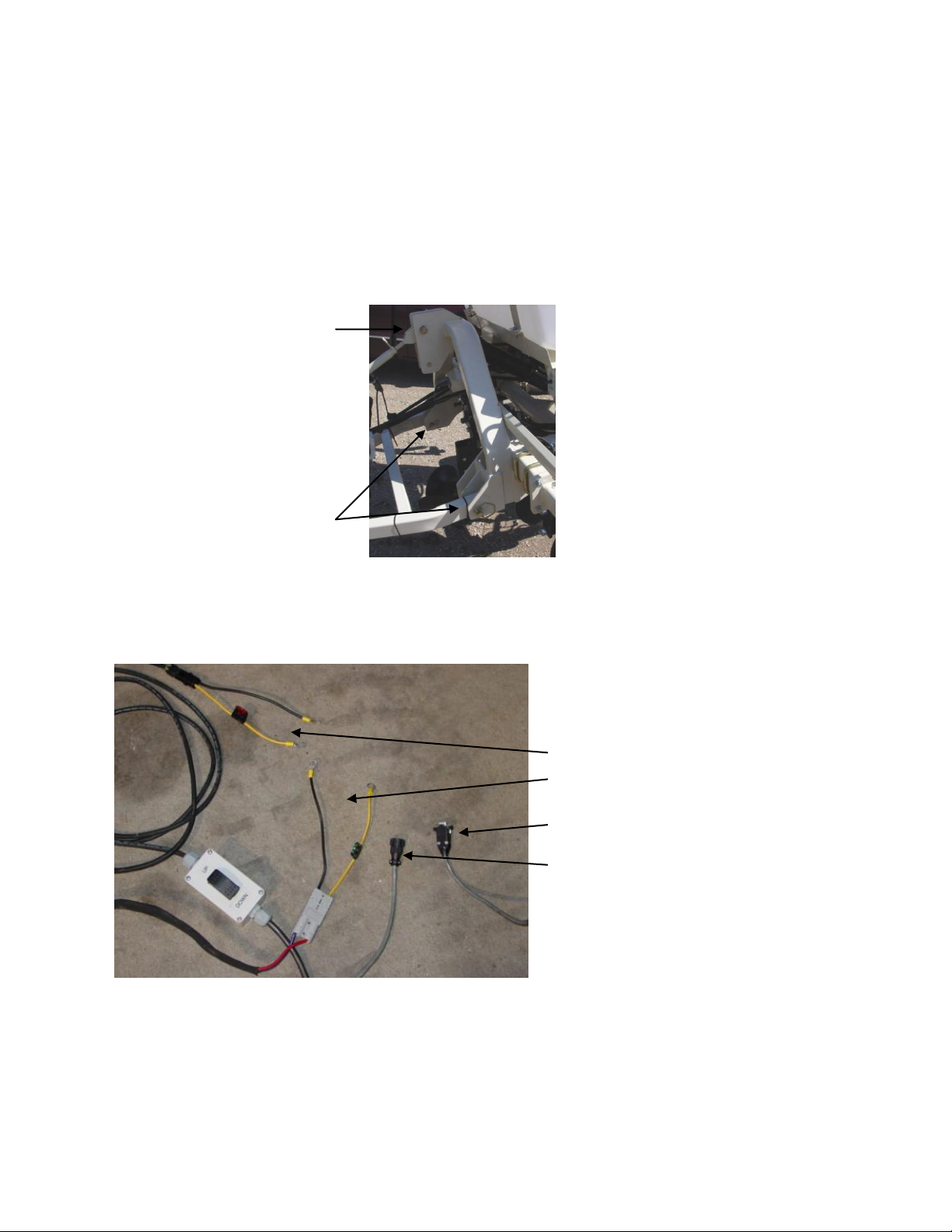
Install 7/8”
pins here
Install 1” pin
here
12 V Power leads
-raise-lower
-external control module
pH signal cable (if equipped)
EC signal cable
Pub. #OM MSP03-1
Soil EC Surveyor
Installation and Set-up
If the unit has been crated and delivered via closed-van commercial freight, the tongue (if equipped)
may need to be installed prior to use. before doing so, please take precautions to ensure that the
framework is properly supported to ensure safety.
Remove bands that attach tongue assembly to shipping pallet. Use a forklift or small loader to
position tongue assembly to allow insertion of pins connecting tongue and toplink to MSP mainframe.
Prior to operating the implement for the first time, it is important to check all fasteners – some may
have loosened during shipment.
Route cables and hydraulic hoses along tongue and through hose guide. Tie-strap securely.
Connect signal cable to Veris instrument EC Signal port and electrical cables to battery. Be careful to
attach black cables to negative/ground terminal. DO NOT REVERSE POLARITY.
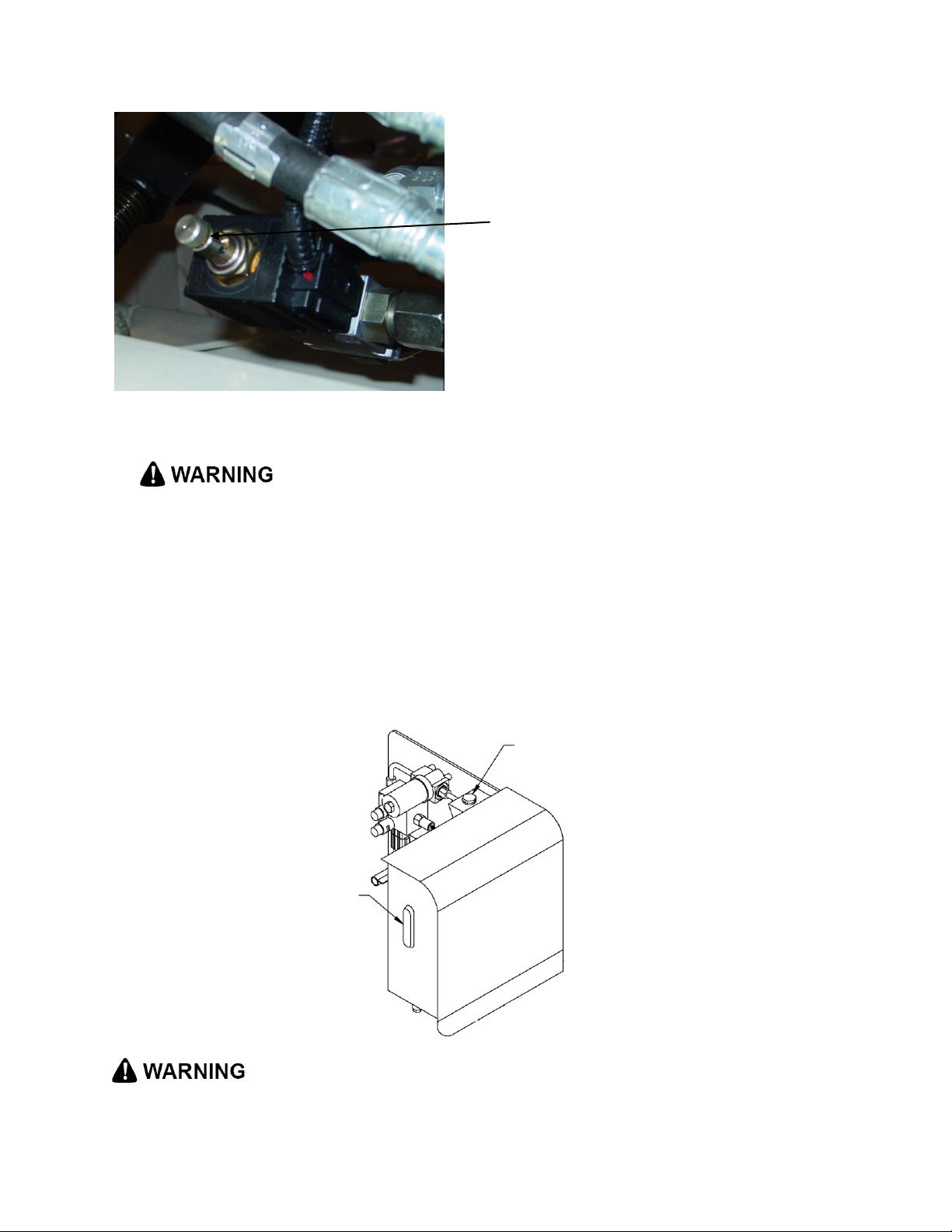
If unit is equipped with hydraulic power pack, insert hydraulic ends into quick-couplers, being careful
to insert the end marked “P” into the pressure or oil output coupler, and the end marked “T” into the
tank or return line coupler. Note: if not using Veris-supplied hydraulic power pack, be certain that
tractor or hydraulic power source is equipped with open-center hydraulics. If tractor has closed center
hydraulics, make sure MSP is equipped with Closed Center Hydraulic Kit (part #26369) and that
poppet valve is in closed center position (in).
Page 11
Veris Technologies
11
hydraulic oil filler plug
hydraulic oil
sight glass
Closed center
hydraulic kit
poppet valve
Pub. #OM MSP03-1
Fill gasoline engine and check engine and hydraulic oil levels.
Before filling tank with gasoline, let engine cool. Gas vapors can ignite
and an explosion can occur.
Checking the hydraulic fluid level is easy thanks to a sight glass on the hydraulic reservoir. The sight
glass is located on the front of the reservoir. Maintain the hydraulic fluid within 1/2 inch (1.25 cm) of
the upper (solid black) line on the glass. Remove the threaded plug from the filler neck to add fluid.
ALWAYS CHECK HYDRAULIC FLUID LEVEL WHEN FLUID IS COLD. DO NOT OVERFILL. See
Maintenance section for specifications on oil type and quantity. Checking the hydraulic fluid level on
the GS1000 is easy thanks to a sight glass on the hydraulic reservoir. The sight glass is located on
the front of the reservoir which is in turn located on the right side (as viewed from the front) of the
machine (Fig. 3.1). Maintain the hydraulic fluid within 1/2 inch of the upper (solid black) line on the
glass. Remove the threaded plug from the filler neck (Fig 3.1) to add fluid.
Page 12
Veris Technologies
12
operate
implement
parallel to
soil
adjust
toplink to
level
Pub. #OM MSP03-1
• Escaping fluid under pressure can penetrate the skin causing serious injury. Avoid the hazard by
relieving pressure before disconnecting hydraulic lines. Use a piece of paper or card-board, NOT
BODY PARTS, to check for suspected leaks.
• Wear protective gloves and safety glasses or goggles when working with hydraulic and highpressure wash systems.
• If an accident occurs, see a doctor immediately. Any fluid injected into the skin must be surgically
removed within a few hours or gangrene may result.
Field Operations—Soil EC Surveyor
Checking Electrical Signal Continuity and Electrode Isolation
It is recommended that you routinely check the EC signal to verify that all functions are working
properly. See Maintenance and Lubrication Section for a step-by-step procedure. It is advisable to
perform this test on a routine basis (weekly or every 20-25 hours of data collection) to ensure you are
obtaining reliable data.
Setting Operating Depth
Begin field operation by lowering unit into soil. For good electrical conductivity, all coulter electrodes
must be in direct contact with the soil, at all times and in every region of the field. A depth of 1-2”
(2.5-5 cm) is recommended. To insure this depth is consistently achieved, 400-600 lbs. (180-275 kg)
of additional weight are normally required. Veris offers optional weights, or they can be supplied by
the customer. If the unit is equipped with the pH module, keeping 40-60 gallons (225-350 L) of water
in the tanks provides ballast. Do not adjust the tension on the coulter electrode springs to increase
soil contact or penetration. They are pre-set at the factory with the proper tension. If unit is equipped
with pH module, it is especially important to keep the implement level during field operation. Adjust
top link to level.
Field Condition
Field should be in a uniform state. Mapping after intensive primary tillage is not recommended. The
soil must have a minimum of 10% available water, and cannot be frozen. If rocky conditions exist, you
may wish to consider the optional coulter rock guard kit , PN 15169.
Speed
Proper field operating speed depends on field conditions. Because of the importance of consistent
contact, the unit must not be allowed to bounce over rough fields at high speeds. On smooth fields,
the implement can be operated at speeds from 8-12 m.p.h. (12-18 km/hr)
Pulling Vehicle
The implement may be pulled with a variety of vehicles: 20-50 hp tractor, 4WD pickup or Jeep.
Swath width and Navigation
Setting the swath width and navigation system is at the discretion of the customer. A 40-60’ (12-18
m) swath works well in most areas. In areas of high soil variability, a narrower swath may be
preferred. Several methods of navigation are possible: following previous crop rows, swath guidance,
or using a field navigation computer. While it is important to map in a consistent pattern, it isn’t
absolutely critical that each pass be exactly the same distance from the previous pass.
Page 13
Veris Technologies
13
set screws and jam
nuts
Pub. #OM MSP03-1
Signal Cable
Attach the signal cable to the quick connect coupler at front of frame, and to Signal Port on back of
instrument
Adjustable Wing Extensions (XA option)
The MSP3150 with XA (Extendable Array): This option allows the re-positioning of the electrodes to
fit various bed and crop configurations. Adjustment is made by loosening the jam nuts and set
screws located on the lower front of each side of the toolbar, adjusting the toolbar wing extensions,
and re-tightening the set screws. Veris suggests setting the toolbars at either the maximum or
minimum setting, not at a point in between. A limiter bolt determines full extension, so there should be
no danger of extending to the point at which the outside coulters disconnect from the main frame.
Important – do not attempt to combine maps in which two different investigative depths are used.
• Pinch point hazard: to prevent injury, stand clear when raising or lowering any part of the Veris
MSP. Disengage automatic cycling function before working around unit.
• Install all transport locks before transporting or working underneath.
Collecting Soil EC Data
If unit is equipped with pH Module, and you are not collecting pH data, remove sampler shank and
raise row cleaner and covering disks.
Page 14
Veris Technologies
14
DGPS indicator:
NONE, _GPS,
DGPS
Shallow and
Deep EC
readings
pH readings from each
electrode if equipped
with pH module
Status of pH
sampling
mechanism
Speed in
MPH
Pub. #OM MSP03-1
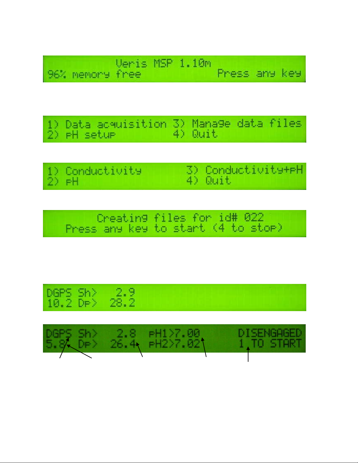
Turn on Veris instrument. The first screen to appear contains the software version number and
shows how much logging time is available.
The computer is informing you of how much of its internal memory is available. Check available
memory to be sure you have enough to contain the data from field you are about to map.
Options: Press any key and proceed to menu options.
Press 1 to bring up the data acquisition menu (see below for more details) (setup options are only for
pH data acquisition, and are covered in pH Module manual)
Select the type of data you want to collect from the above menu.
Regardless of the type of data selected in the previous menu, the computer will show the name of the
map file it is creating, in case you want to record it along with any other information about the field.
Press any key to begin new map file (after starting the file, press the 4 key to stop the file).
Pressing any key brings you one of the following Data Acquisition screens below:
E.C. only (option 1):
E.C. and pH (option 3):
The display is showing the pH values from the pH electrodes, conductivity of the top 1’ (30 cm) and
top 3’ (90 cm) of the soil, and whether you have GPS or DGPS (differentially corrected) signal. At
any time during the mapping process, you can press the 4 key to stop the file. If you create more
than one file from the same field, you can bring the files into a spreadsheet program and combine
them prior to mapping.
Page 15
Veris Technologies
15
no
continuity
grounded
bolt
coulter
terminal
Pub. #OM MSP03-1
SEE GENERAL INFORMATION SECTION FILE MANAGEMENT FOR INSTRUCTIONS ON
DOWNLOADING DATA
Maintenance and Lubrication
Proper maintenance and lubrication of the Veris MSP will allow you to collect high quality EC data
and greatly extend the useful life of the unit. Veris Technologies strongly suggests that you follow the
following guidelines:
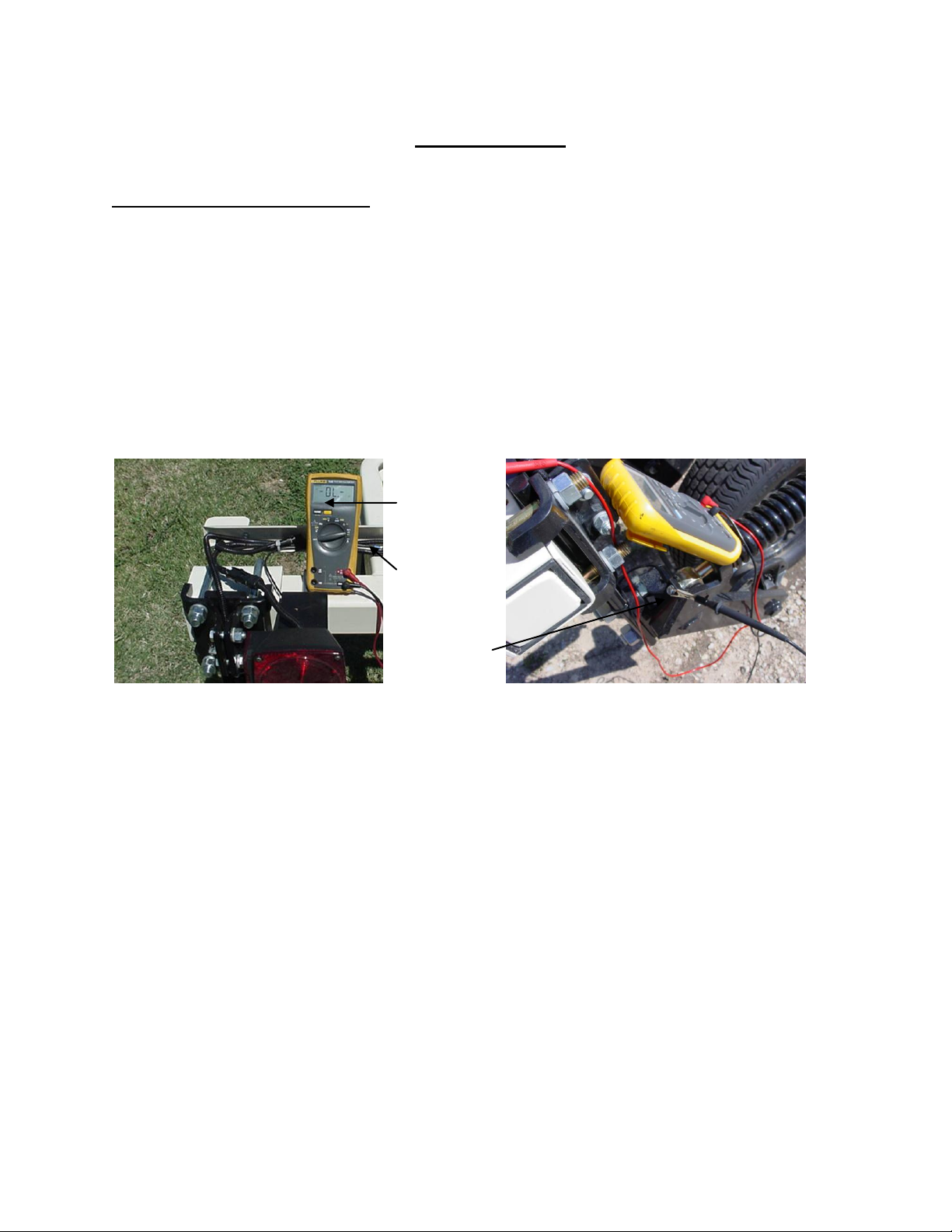
MAINTENANCE: Electrical Continuity and Isolation
It is advisable to perform this test on a routine basis (weekly or every 20-25 hours of data collection)
to ensure you are obtaining reliable data.
1) Coulter electrode isolation – check so see that no metal part of the any coulter
electrode is in contact with the implement frame. This may be by visual inspection or by
connecting one lead of an ohmmeter to the individual coulter electrode, and the other to a
grounded fastener on the frame. If the coulter electrode is properly isolated, no reading
will be obtained. Make sure that all electrode coulter clamp bolts are properly tightened to
prevent lateral movement of the coulter electrode.
2) Signal Continuity – To properly measure conductivity, good electrical signal continuity
must be present from the coulter electrode to the instrument. The Implement Test Box
(Part No. 10759) allows you to quickly check this.
Use the following method:
a) Connect the signal cable to the terminal on the test box.
b) Touch one lead of an ohmmeter to the #1 coulter blade (left hand, standing behind
the unit) and the other lead to the #1 terminal on the test box. A reading of less than
2 ohms is normal.
Page 16
Veris Technologies
16
Connect to
coulter blade
Ohmmeter
Connect one lead to Test
Box terminal (corresponding
to each coulter)
Test Load
Pub. #OM MSP03-1
c) Continue to check each coulter electrode in succession, left to right.
d) If any coulter electrode exhibits no continuity or resistance higher than 2 ohms, refer
to the maintenance or trouble shooting sections for possible causes.
Note: It is advisable to perform this test on a routine basis (weekly or every 20-25 hours
of data collection) to ensure you are obtaining reliable data.
Instrument Signal Testing – The Veris MSP pH Manager is shipped with an Instrument Test Load
(Part No. 10447) that will enable you to quickly check the instrument to ensure that it is functioning
properly. To perform this test, do the following:
1) Disconnect the signal cable from the 9-pin (signal) terminal on the instrument.
2) Connect the test load to the signal terminal.
3) Switch on the unit and go into “data acquisition” mode.
4) The display should show: (approx.)
Deep 27
5) If the readings vary significantly (more than one whole number) contact our service
department.
6) Once the test is complete, remove the test load and reinstall the implement signal cable.
Shallow 3
Note: It is advisable to conduct this test as a routine check to ensure that you are obtaining reliable
EC data.
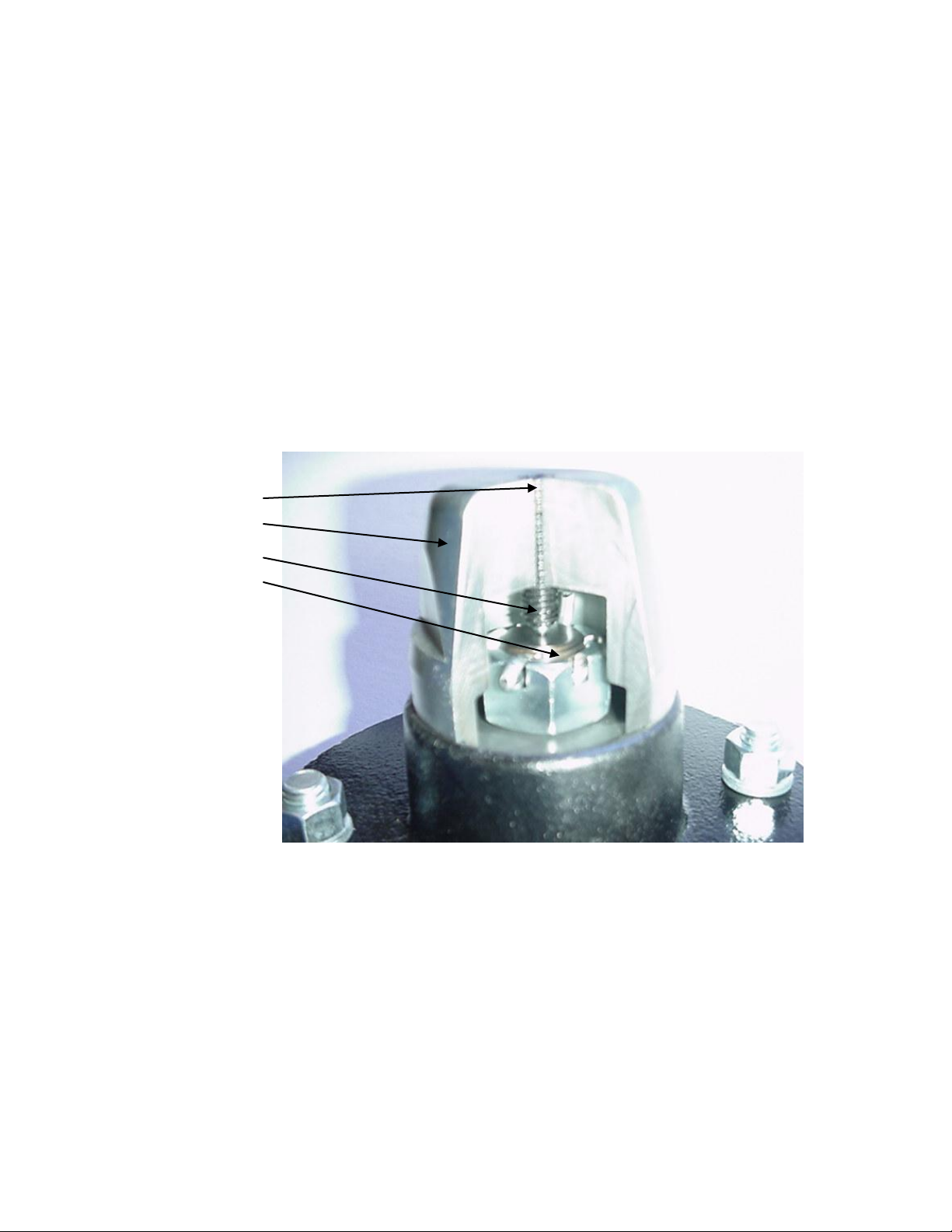
ADJUSTMENTS
Commutators-- The spring-loaded commutators are located in the center of each coulter
electrode hub cap. They are factory preset, and should not need
routine adjustment. If a continuity test shows abnormally high resistance,
Page 17
Veris Technologies
17
cap
commutator
set screw
spindle
Pub. #OM MSP03-1
the commutators should be checked. This may be performed in the following
manner:
1) Remove the 3/8” allen head set screw.
2) Remove the commutator by turning counter-clockwise.
3) Depress the spring loaded tip on a hard surface to determine if
plunger has adequate tension and can move freely.
4) If the plunger will not move freely, replace, and coat with di-electric
silicone grease.
5) If the commutator appears to be in good working order, reinstall in the
hub, and adjust until it bottoms against the spindle end. Rotate 1/2 turn
backward to allow adequate clearance. Improper adjustment will result in
premature failure (too little tolerance) or poor continuity (too much
tolerance).
6) Reinstall locking set screw and tighten firmly on top of commutator. The
top of the set screw should be even with the face of the hub. If not,
remove and adjust the commutator inward or outward as necessary.
7) Re-test coulter electrode continuity.
Here is a cut away view of the hubcap assembly:
Note: If you are still unable to obtain favorable resistance readings, check for
excessive corrosion at the coulter blade mounting bolts, or the terminal located
near the coulter pivot. It may be necessary to grind the spindle end smooth, if a
dimple has developed.
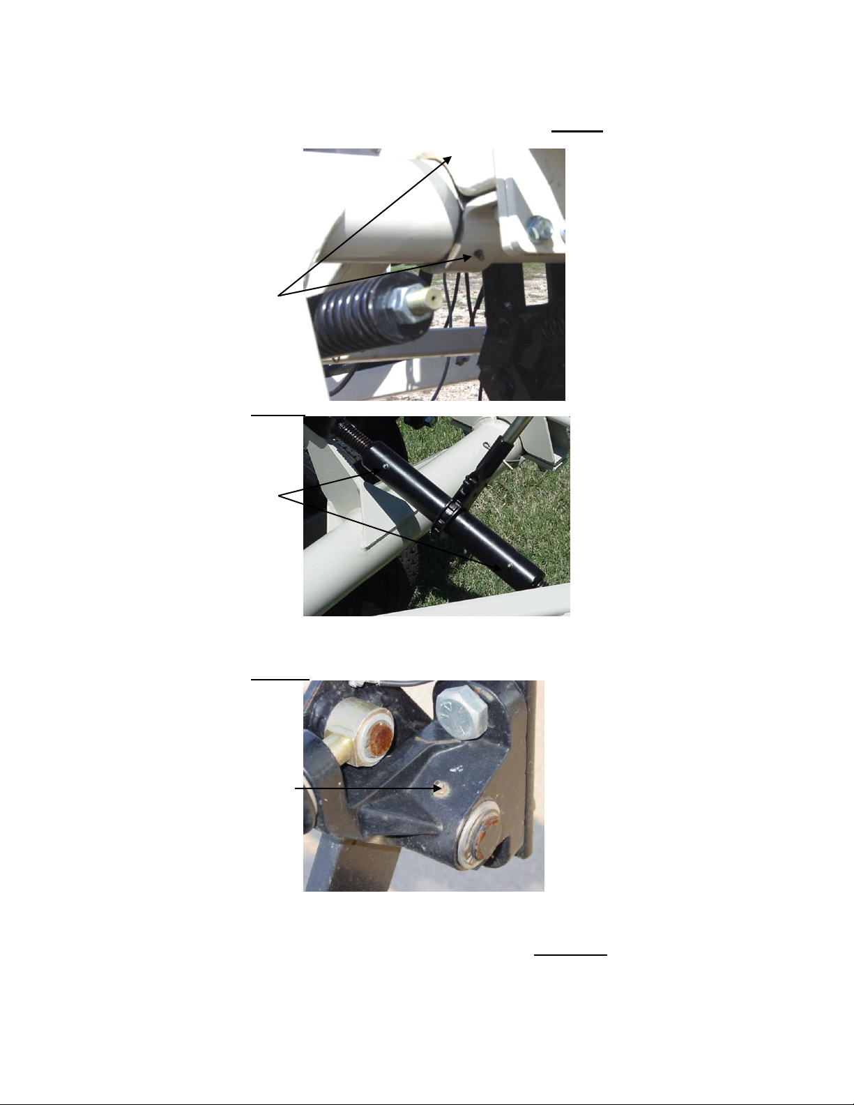
MAINTENACE: LUBRICATION
Rockshaft pivot points – Each pivot (located at the left and right) contains
Page 18
Veris Technologies
18
Pivot grease
zerks (2 per
hangar; 4 total )
grease zerks
grease zerk
Pub. #OM MSP03-1
an upper and lower grease zerk. Due to the limited motion of the
rockshaft, these should be lubricated on 40-hour intervals. This may
vary based on the number of times the unit is raised and lowered.
Rachet jack -- 20 hour intervals
Electrode coulters
Pivot -- In all but the most extremely rocky conditions, the coulter electrodes should
not flex in the field, thus minimal movement will be realized at the pivot.
80-hour intervals should be sufficient.
Hubs -- Use good quality wheel bearing or lithium grease for lubrication, but we
suggest that you grease the hubs sparingly. Over-lubricating the hub
will result in pre-mature seal failure, and an excessive amount of grease
in the hub cap/commutator. On an interval of 150 hours, 1-2 strokes of
grease should be sufficient.
Page 19
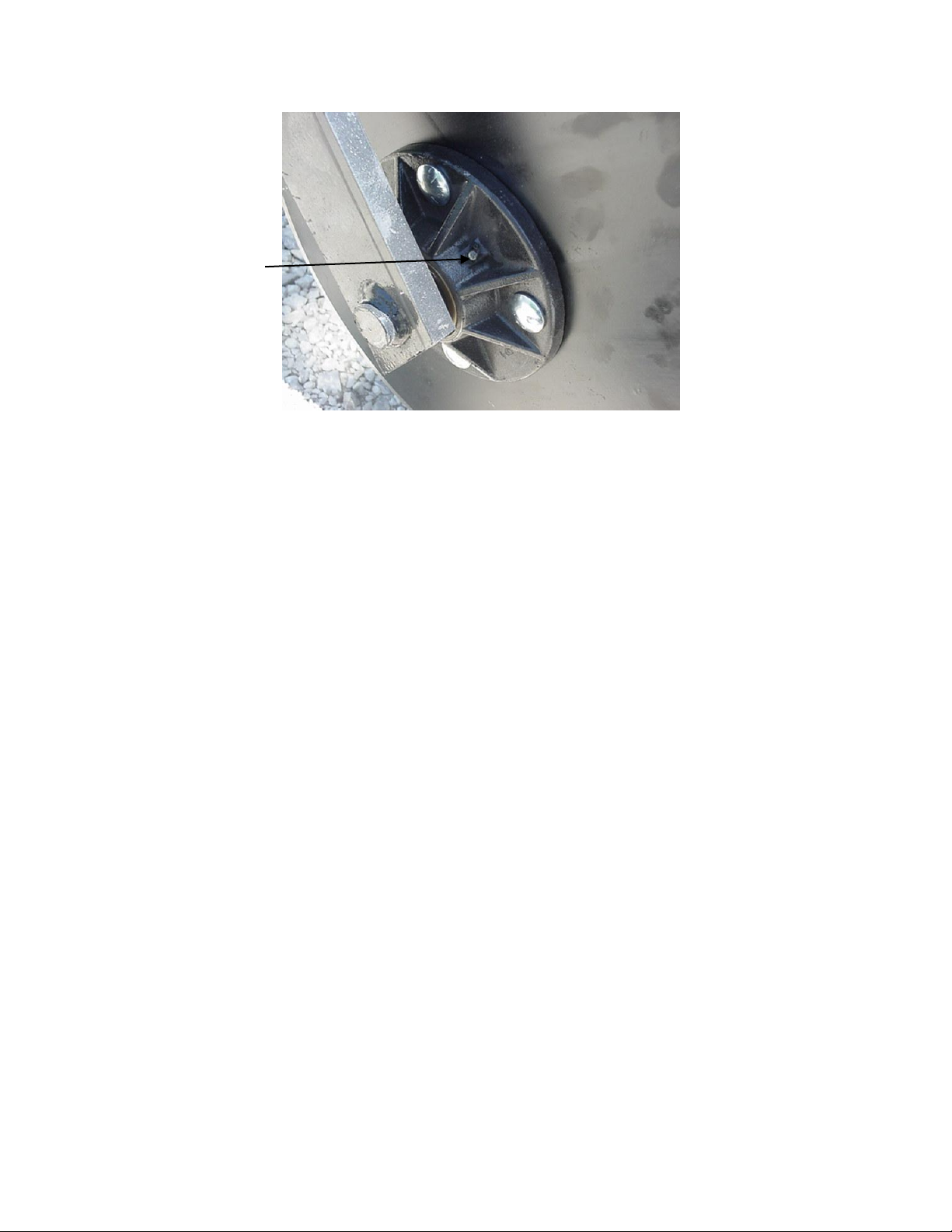
Veris Technologies
19
grease zerk
Pub. #OM MSP03-1
Wheel hubs -On an annual basis, disassemble, clean, and properly repack the wheel
hubs with suitable wheel bearing grease. It is advisable to replace the seals.
As with any tapered roller bearing, proper pre-load will extend the
life of the assembly. Fully tighten the nut, then rotate backward up to ¼
turn, so that the hub turns freely, without endplay. Install cotter pin, and
reinstall hub cap.
Coulter electrode
hubs -- The coulter electrode hubs operate in a significantly harsh environment,
and annual inspection is of utmost importance. The double-lip seals are
designed to keep grease in, and contaminates out, but they are the cause of
practically all hub failures. It is advisable to disassemble, clean, repack, and
re-install annually. To perform this maintenance, do the following:
1) Remove hub cap by turning in a clockwise direction (left-hand thread
prevents loosening in operation).
2) Remove cotter pin, castle nut, thrust washer, and remove hub.
3) Remove outer bearing and knock out inner bearing using a wooden
dowel or brass rod. Be sure to match each bearing to its location on the
hub and do not mix bearings between hubs. Natural wear will cause the
bearing and race to form pattern that is unique to that set.
4) Thoroughly wash hub and bearings in solvent and dry.
5) Replace bearings and races that show excessive wear or pitting.
6) Pack with grease, and reassemble -- or reassemble, and pack via grease
zerk with wheel bearing or lithium grease. It is advisable to replace the
seals.
7) Adjust bearing pre-load as mentioned above. Excessive pre-load may
cause plugging in extremely loose soil conditions, and excessive endplay
may damage the commutators.
8) Inspect the sealing o-ring on the hub cap, and reinstall by threading
counter-clockwise on the hub.
9) Adjust commutator clearance as mentioned above in section on
commutator adjustments.
Page 20

Veris Technologies
20
Seal
Hub
Nut
Thrust Washer
Bearing
Swing arm
Pub. #OM MSP03-1
Page 21

Veris Technologies
21
Pub. #OM MSP03-1
EC MODULE TROUBLESHOOTING
Map doesn’t match known or expected soil types --
1. Check electrical continuity using Implement Test Box as discussed above.
2. Check isolation of coulter electrodes
3. Remove any buildup of moist soil on toolbar
4. Check blade bolt tightness and corrosion
5. Map additional fields to see if similar condition results
6. Contact Veris Service Department
EC values change with field speed, or when unit stops moving
(If both shallow and deep EC array values change, focus on coulters 2 & 5; if shallow array coulters 3
& 4; if deep array coulters 1 & 6)
1. Check electrical continuity carefully—rotating coulter blade as measurement is made
2. Remove coulter hub cap and inspect spring-loaded commutator and coulter spindle for wear;
replace commutator or grind spindle end smooth if necessary
No conductivity readings on instrument display--
1. No continuity on coulter electrode # 2 or # 5.
2. Check for excessive corrosion on coulter terminal.
3. Check for broken signal wire by disconnecting wire from coulter electrode and checking
continuity from end of wire to corresponding terminal on test box. Replace coulter wiring (PN
15601) or signal cable (PN 13602) as required.
4. Check for collapsed spring-loaded commutator on # 2 or # 5.
Data missing from display reading –
1. Unit must be in contact with soil to record data points; lower unit or add weights to ensure
consistent 1”-2” (2.5-5 cm) penetration into soil
2. Check GPS and DGPS signal; Veris instrument is programmed to eliminate all non-DGPS geo-
referenced points.
3. Shut power off and restart
4. Check electrical continuity: coulter electrodes to terminal…terminal to instrument.
5. Check input voltage, 12 v minimum required
Excessive number of negative readings in data --
1. Increase depth of penetration.
2. Slow down in extremely rough fields.
3. Alter transect pattern to avoid areas of heavy residue (combine swath)
Instrument has “locked up” and is not responding --
1. Shut off power and restart. Download the file that you were creating at the time the problem
occurred. Continue mapping the field. The files can be combined later in your spreadsheet.
2. Check for diskette in drive. Do not start up the instrument with a diskette inserted in the drive.
File will not download –
1. Try again
2. Check to see if you are receiving DGPS signal; system eliminates all non-DGPS geo-referenced
points
3. Restart computer and try again
4. Try another diskette.
5. Use Rescue Disk (Veris part #12330) to download files. Follow instructions on Rescue Disk
label.
6. Use serial port download function
Time or date on instrument display is incorrect or needs to be reset for new time zone--
1. Insert Time Set Disk (Veris part #-12331) to adjust time or date. Follow instructions on Time Set
Disk.
Page 22

Veris Technologies
22
12 V Power leads
-raise-lower
-external control module
pH signal cable
EC signal cable (if equipped)
Closed center
hydraulic kit
poppet valve
Pub. #OM MSP03-1
pH Manager
Installation and Set-up
If the unit has been crated and delivered via closed-van commercial freight, the tongue (if equipped)
may need to be installed prior to use. Before doing so, please take precautions to ensure that the
framework is properly supported to ensure safety.
Remove bands that attach tongue assembly to shipping pallet. Use a forklift or small loader to
position tongue assembly to allow insertion of pins connecting tongue and toplink to MSP mainframe.
Prior to operating the implement for the first time, it is important to check all fasteners – some may
have loosened during shipment.
Route cables and hydraulic hoses along tongue and through hose guide. Tie-strap securely.
Connect signal cable to Veris instrument Output port and electrical cables to battery. Be careful to
attach black cable to negative/ground terminal. DO NOT REVERSE POLARITY.
Insert hydraulic ends into quick-couplers, being careful to insert the end marked “P” into the pressure
or oil output coupler, and the end marked “T” into the tank or return line coupler. Note: if not using
Veris-supplied hydraulic power pack, be certain that tractor or hydraulic power source is equipped
with open-center hydraulics. If tractor has closed center hydraulics, make sure MSP is equipped with
Closed Center Hydraulic Kit (part #26369) and that poppet valve is in closed center position (in).
Page 23

Veris Technologies
23
hydraulic oil
filler plug
hydraulic
oil sight
glass
engine oil
dipstick
Pub. #OM MSP03-1
Before filling tank with gasoline, let engine cool. Gas vapors can ignite and
an explosion can occur.
Fill gasoline engine and check engine and hydraulic oil levels. Checking the hydraulic fluid level is
easy thanks to a sight glass on the hydraulic reservoir. The sight glass is located on the front of the
reservoir. Maintain the hydraulic fluid within 1/2 (1.25 cm) inch of the upper (solid black) line on the
glass. Remove the threaded plug from the filler neck to add fluid. ALWAYS CHECK HYDRAULIC
FLUID LEVEL WHEN FLUID IS COLD. DO NOT OVERFILL. See Maintenance section for
specifications on oil type and quantity. Checking the hydraulic fluid level on the GS1000 is easy
thanks to a sight glass on the hydraulic reservoir. The sight glass is located on the front of the
reservoir which is in turn located on the right side (as viewed from the front) of the machine (Fig. 3.1).
Maintain the hydraulic fluid within 1/2 inch of the upper (solid black) line on the glass. Remove the
threaded plug from the filler neck (Fig 3.1) to add fluid.
• Escaping fluid under pressure can penetrate the skin causing serious injury. Avoid the hazard by
relieving pressure before disconnecting hydraulic lines. Use a piece of paper or card-board, NOT
BODY PARTS, to check for suspected leaks.
• Wear protective gloves and safety glasses or goggles when working with hydraulic and high-
pressure wash systems.
• If an accident occurs, see a doctor immediately. Any fluid injected into the skin must be surgically
removed within a few hours or gangrene may result.
Flush and fill tanks with tap water; clean any foreign matter out of tank using ball valve clean-out. Set
ball valve to open position, allowing water to flow to pumps.
Page 24

Veris Technologies
24
ball valve:
closed
open
pH
electrodes
electrode set
screws and
lock nuts
electrode
holder
soaker
container
Pub. #OM MSP03-1
Connecting cables to External controller as shown below:
Remove pH electrodes from individual storage containers and fill soaker solution container with
soaker solution. Install soaker solution container on electrode holder. Loosen plastic set screws on
electrode holder and insert pH electrodes into electrode holder. Re-tighten set screws finger tight and
lock in place with lock nuts. Do not overtighten set screws or electrode damage may occur. Always
keep electrodes in soaker solution, either in individual containers or soaking in large container
installed over electrode holder. Route electrode cables away from sampling mechanisms to prevent
damage—tie-strap excess length of cable as needed.
Page 25

Veris Technologies
25
throttle
choke
fuel valve
ignition key
external
Raise/Lower
switch
cab
Raise/Lower
switch
Pub. #OM MSP03-1
Field Operations
Tools required for Field Operation adjustments
-3/16” allen wrench
-adjustable wrench: min. 10” (25 cm) length
-3/4” socket and wrench
-9/16” socket or wrench
-15/16” wrench
Starting Engine
Turn fuel valve to On position by sliding it to the far right. Move the choke lever to the far left Closed
position, if engine is cold. Slide the throttle lever slightly to the left. Turn the engine switch to the on
position. Turn key on. As engine warms up, gradually move choke lever to the far right Open
position. Position the throttle lever to maximum engine RPM.
• Pinch point hazard: to prevent injury, stand clear when raising or lowering any part of the Veris
MSP. Disengage automatic cycling function before working around unit. Install all transport locks
before transporting or working underneath.
Manually Operating Wash and Cycling Functions
1. After all cables and hydraulic hoses are connected, start engine and test unit by raising and
lowering MSP unit using external or cab Raise/Lower switch. Make sure no one is under unit and
keep clear of any pinch points.
Page 26

Veris Technologies
26
begin with shank in
one of two middle
positions
begin with 2-3”
(5-7.5 cm) of
depth stops
adjust
toplink to
level
Power switch
must be on to
operate any
function
MANUAL CONTROLS:
Manual-Auto switch:
must be in Automatic
mode for mapping;
in Manual mode for
manual control of
washing or sampler
shoe position
Sampler up and down:
raises sampler shoe
manually
Pinch point hazard
Wash: On when washing
manually; Off for
Automatic washing
Pub. #OM MSP03-1
2. Put external controller in Manual mode and raise and lower sampler assembly. Keep
appendages clear of pinch points.
3. Turn wash system on. If water does not flow from jets within 10 seconds, disconnect quick
couplers to help pumps prime. If water doesn’t flow from pump outlet after 10 seconds, see
Trouble-shooting section.
Field Operation Adjustments
• Pinch point hazard: to prevent injury, stand clear when raising or lowering any part of the Veris
MSP. Disengage automatic cycling function before working around unit. Install all transport locks
before transporting or working underneath.
1. Raise sampling mechanism to full height. Begin depth adjustment process with shank in middle
position (pin in one of two center holes). Install 2-3“ (5-7.5 cm) of cylinder depth stops on main lift
cylinder. Lower implement into soil until main lift cylinder bottoms out against depth stops. Adjust
threaded toplink to level unit.
Page 27

Veris Technologies
27
pull adjustment
pins and lower
shank if deeper
sampling is needed
(and EC coulter
depth is
satisfactory)
operate
implement
parallel to
soil
sampling depth is
measured from top
of cutting shoe to
soil surface
Pub. #OM MSP03-1
2. Once unit is level, lower sampling mechanism completely, drive forward 10-20’ (3-6 m) to create
soil core. To measure depth of soil core being collected, brush away soil from cutting shoe.
Measure from soil surface to top of cutting shoe. This is the depth of sampling. To increase
sampling depth, remove cylinder stops; to decrease sampling depth, add stops. Re-leveling unit
with adjustable toplink may be required.
3. Note: if MSP is equipped with EC Module and EC data is being collected along with pH data,
adjusting the overall height of the unit will affect coulter-electrode depth. If deeper soil sampling
is desired, and removing cylinder stops would result in excessive coulter-electrode depth, remove
sampler shank pins and lower shank to lowest setting. If shallower soil sampling is required, and
adding cylinder stops results in inadequate coulter-electrode depth for EC data collection, raise
sampler shank to highest setting.
Page 28

Veris Technologies
28
Turn crank to raise or
lower electrode holder
electrode
holder 1”
(2.5cm)
above wash
jets
Adjust scraper bracket until
cutting shoe clears scraper
when sampler assembly is
raised completely.
½” (1.2 cm) clearance
between electrode
holder and trough liner
Pub. #OM MSP03-1
Other Field Adjustments
Once EC coulter depth and sampling depth are satisfactory, adjust other components in this
sequence:
1. Scraper adjustment: in manual mode hydraulically raise the sampling shoe to maximum
height. Adjust scraper until cutting shoe clears scraper blade when sampler shank is fully
raised.
2. Adjust electrode holder: with sampling mechanism raised completely, adjust electrode holder
to provide ½” (1.2 cm) clearance between it and sampling trough.
3. Wash adjustment: Wash brackets should be parallel to sampling trough, with jets directly
beside electrode holder, jets should be 1” (2.5 cm) below electrodes; when electrodes are
properly aligned.
Page 29

Veris Technologies
29
Closing Disks
depth adjustment
pin
Closing Disks
angle
adjustments
When wash jets are
properly aligned,
overspray is
minimized and water
bubbles out top of
electrode holder as
shown here.
Adjust height of cleaner relative
to firming wheel by removing
adjustment pin and repositioning disk attachment.
When installing BNC cover, route
electrode wires under box; center
box on white pad, and tighten
wingnut finger tight. Keep cover
installed even when electrodes
are removed.
Pub. #OM MSP03-1
4. Insert pH electrodes into electrode holder. Finger-tighten plastic screws. Install BNC cover
on external controller to keep moisture out of BNC connectors. Leave BNC cover on
whenever unit is outdoors.
5. Row cleaner/firming wheel (if equipped): Pull MSP forward and check depth of row cleaner
and firming wheel. Cleaner should be clearing residue ahead of sampling shoe, but not
gouging into soil. Adjust height of cleaner relative to firming wheel by removing adjustment
pin and re-positioning disk attachment.
6. Closing disks (if equipped): Adjust closing disks as needed to properly close trench and bring
residue over row-cleaned zone. Do not operate these deeper in soil than necessary.
Page 30

Veris Technologies
30
Light is on as metal
passes by sensor
Prox Sensor light
1/4 to 3/8” gap
Light is off
when sensor
is above and
below plate,
and over
center gap
Pub. #OM MSP03-1
7. Prox sensor: The prox sensor communicates the position of the sampler assembly to the
external controller for automatic cycling functions. Adjust sensor to 1/4”- 3/8” (6-9 mm) gap.
Cycle unit manually to insure that this gap is maintained throughout cycling range. Red LED
light should light whenever prox sensor is near metal and not light when away from metal. To
view LED light, shade ambient light from prox sensor and cycle sampler assembly manually.
Be careful to not strike or damage prox sensor face. Adjust prox sensor height with sampler
shoe completely raised. Adjust the prox sensor so it barely clears the lower part of the sensor
plate when sampler is completely raised. It may be necessary to reposition the electrode
holder after adjusting prox sensor; see step 2 above.
Installing electrodes
pH Electrode Calibration Procedure: perform daily
1. Thoroughly wash the electrodes and electrode holder; wash for 30-60 seconds before
calibrating and between each solution.
2. Wipe the electrode holder dry; gently dry the electrode holder face and electrodes with a paper
towel. Do not touch the face or dome of the electrode.
3. Turn on the Veris Instrument.
4. Enter menu option 2) pH Setup:
5. Enter menu option 1) Calibrate ISE’s:
6. Enter menu option 1) Continue calibration.
Page 31

Veris Technologies
31
Pub. #OM MSP03-1
7. You will be asked for the ID of the electrode connected to channel 1. Use the 1 and 2 keys to
change the number and 3 to confirm:
Repeat for electrode 2’s ID and press 3 to confirm.
8. The instrument will prompt for the electrodes to be inserted into pH buffer 4 solution; Slide pH 4
buffer solution container onto electrode holder. Press 1 to continue with calibration or 2 to exit.
9. The instrument will read the electrodes for 10 seconds, displaying the output (as it counts
seconds):
10. After 10 seconds, the instrument will display the final pH reading and offer the options to 1)
Accept pH 4 buffer readings; 2) Redo pH 4 buffer readings; or 3) Exit pH electrode calibration.
If the readings are satisfactory, log pH 4 reading and press 1; if the readings are suspect, press
2 to return to step 8.
11. After accepting the pH 4 buffer readings, the Instrument will prompt for the electrodes to be
inserted into pH 7 buffer solution.
12. Remove the pH 4 buffer solution container from the electrode holder.
13. Rinse the electrodes and electrode holder using the manual wash or handheld wand for at least
20 seconds.
14. Wipe the electrode holder dry; gently blot the electrode holder face and electrodes with the
edge of a paper towel.
15. Slide the pH buffer 7 solution container onto the electrode holder.
16. On the Instrument, press 1 to continue with calibration or 2 to exit.
17. The instrument will read the electrodes 10 seconds, displaying the output.
18. After 10 seconds, the instrument will display the final pH reading and offer the options to 1)
Accept pH 7 buffer readings; 2) Redo pH buffer 7 readings; or 3) Exit pH electrode calibration.
Page 32

Veris Technologies
32
Pub. #OM MSP03-1
If the readings are satisfactory, log pH 7 reading and press 1; if the readings are suspect, press
2 to return to step 16.
19. After accepting the pH 7 buffer readings, the Instrument will determine if each electrode’s
response is sufficient to provide suitable readings. A score is displayed for each electrode; the
acceptable score range is between 75 and 102. If both electrodes are within this range, the
instrument will display the following screen:
20. If an ‘X’ is displayed beside one or both electrodes’ scores, this indicates that one or both of the
electrodes did not perform well enough for continued reliable use. No calibration settings are
changed if calibration is unsuccessful. The electrode(s) responsible for failed calibration should
be removed and either cleaned or replaced and the calibration procedure repeated. See
Maintenance section for electrode cleaning instructions.
21. After calibration is complete, you will have the option to use the calibrated readings or reset to
the default parameters.
22. The results of calibration are stored in a file on the instrument. for instructions on downloading
and/or deleting this file, see below.
Downloading/deleting electrode log file
1. Enter menu option 2) pH Setup:
2. Enter menu option 2) Manage ISE file:
3. From this screen, press 1) to download the electrode log file or 2) to delete the log file.
4. To download the file, select option 1. The ISE log file will be recorded to the CF card. The file
is named ISE.TXT and will contain information about electrode calibration. Here is an example
file:
Page 33

Veris Technologies
33
Pub. #OM MSP03-1
Collecting pH data
Set external controller to Automatic mode. Turn on Veris instrument. The first screen to appear
contains the software version number and shows how much memory is available.
Check available memory to be sure you have enough available to contain the data from field you are
about to map. Options: Press any key and proceed to menu options.
Press 1 and begin acquiring data (see below for more details). Press 2 and enter Setup menu.
(Press 3 to Exit this window).
Press 1 to calibrate pH electrodes as described above. Press 2 to download or delete the electrode
log file as described above. Press 3 to adjust the pH controller’s settings.
Sampling time is the duration that the sampler assembly is in the soil. Typically 2 seconds is
adequate. In soil conditions that do not produce a firm core, this time may need to be set at 3
seconds in order to allow soil to begin flowing through cutting shoe. If soil conditions result in a very
firm core, the sampling time may be reduced to 1 second. Press 1 or 2 to adjust the sample time,
press 3 to continue to the next screen.
Page 34

Veris Technologies
34
Pub. #OM MSP03-1
Maximum log time is the longest time in seconds the pH controller will wait for the pH readings to
settle. The controller usually cycles before this maximum time is reached. The minimum setting for
the maximum log time is 20 seconds. Press 1 or 2 to adjust the sample time, press 3 to continue to
the next screen.
Select the type of water you are using to clean the electrodes between samples. The available types
are TAP, RO (reverse osmosis), or DI (de-ionized). Press 1 or 2 to cycle through the water types,
press 3 to continue to the next screen.
Turning on the extra wash option will add 1.5 seconds of cleaning per cycle. The extra wash is
performed by stopping the shoe briefly during the cycle. Use this feature if you have noticed the
electrodes are not cleaning during the cycle. Press 1 or 2 to choose ON or OFF, press 3 to continue.
After all of the settings have been entered, the instrument will save the settings and exit to a screen
reading “OK to turn off power Press any key to continue”. Settings are stored in memory and will
remain as set until they changed. Press any key to return to the title screen. Proceed through the
menu to Data Acquisition menu:
Select either 2) pH or 3) Conductivity+pH to collect pH data.
The next screen shows the file number of the files being created in case you want to record it along
with any other information about the field. Press any key to begin new map file (after starting the file,
pressing the 4 key will stop the file):
Pressing any key brings you to one of the Data Acquisition screen below:
pH only (option 2):
Page 35

35
pH and EC (option 3):
DGPS indicator:
NONE, _GPS,
DGPS
Shallow and
Deep EC
readings
pH readings from each
electrode if equipped
with pH module
Status of pH
sampling
mechanism
Speed in
MPH
Veris Technologies
Pub. #OM MSP03-1
The display is showing the pH values from the pH electrodes, conductivity of the top 1’ (30 cm) and
top 3’ (90 cm) of the soil, and whether you have GPS or DGPS (differentially corrected) signal. At
any time during the mapping process, you can press the 4 key to stop the file. If you create more
than one file from the same field, you can bring the files into a spreadsheet program and combine
them prior to mapping.
From this screen, pressing the 1 key as you drive forward will initiate the automatic sampling process.
The software requires movement indicated by the GPS receiver in order to cycle. Speed must
be detected within 5 seconds after pressing 1 or the system will disengage.
If TAP or DI were selected as the wash water type above, the controller will go through a wash
baseline process after engage is pressed for the first time. The status text will change to the
following:
After the pH readings settle (or if RO was selected as the wash water type), the unit will continue
cycling and display the following screen:
“Cycling” means the sampler assembly is in the process of locating its position, washing, and
beginning to lower for soil sampling. After a core has been collected and is being held against the
electrodes, the status text will change to the following:
The pH readings on the display show what each electrode is reading at every second. The sampler
will hold the soil against the electrodes and continue to record pH until the readings settle. The
minimum recording time is 7 seconds; the maximum time is determined in the pH settings menu. The
pH values that are recorded are the final values at the end of the logging duration. (last reading on
the display before the “Cycling” status appears). The final pH value is logged along with the DGPS
position where the sample was collected.
If the electrodes take longer than 10 seconds to settle, a warning will appear by the readings:
and again at 20 seconds:
Page 36

Veris Technologies
36
Pub. #OM MSP03-1
See the troubleshooting section if this occurs frequently.
The Veris MSP pH Manager uses two electrodes for optimal data quality. If there is a difference of
0.75 or greater between the final electrode readings, an audible alarm will beep, informing the
operator of the erroneous reading.
To pause the data collection process at any time (but keep the same file), press the 1 key. Once the
sampling process has completed its cycle, it will disengage and the status text message will indicate
disengaged. (press 1 to start cycling again) If the system no longer senses a speed signal from the
GPS, it will also disengage. NOTE: do not depend on the GPS speed signal for disengagement.
Before inspecting or working around any component of the system, press the 1 key before
exiting the vehicle. Sporadic GPS signals may simulate movement and initiate the cycling
process, resulting in possible entanglement and injury.
If TAP or DI are selected as the wash water type, the water baseline process will be repeated every
40 cycles following the next engage press. If the pH during the cycling sequence does not get within
0.5 of the baseline pH, an audible alarm will sound and the pH labels will blink.
pH Offset and Settings Menu
While the instrument is in pH data acquisition, the pH sampler settings can be adjusted without exiting
the current file. Additionally, a correction can be applied to each electrode’s pH shown on the screen.
Occasionally, the pH readings shown on the screen may differ from those expected in the field. If this
is the case, the pH shown on the screen can be adjusted up or down. To enter the settings screen,
make sure message in the upper right of the screen says DISENGAGED. Press the 3 key. The
following screen will display:
This screen allows you to adjust the offset that will be applied to channel 1’s electrode
reading. The offset is adjustable in 0.5 pH increments up to +/- 2.00 pH. NOTE: The
instrument DOES NOT apply this offset to the extracted file. Only the readings seen on the
screen will be affected. Press 1 or 2 to adjust the reading down or up, and 3 to confirm the
offset and proceed to the next screen.
Similarly, an offset can be applied to channel 2’s electrode. Press 1 or 2 to adjust the offset
down or up, and 3 to confirm the offset and proceed to the next screen.
Sampling time is the duration that the sampler assembly is in the soil. Typically 2 seconds is
adequate. In soil conditions that do not produce a firm core, this time may need to be set at 3
seconds in order to allow soil to begin flowing through cutting shoe. If soil conditions result in a very
firm core, the sampling time may be reduced to 1 second. Press 1 or 2 to adjust the sample time,
press 3 to continue to the next screen.
Page 37

Veris Technologies
37
Pub. #OM MSP03-1
Maximum log time is the longest time in seconds the pH controller will wait for the pH readings to
settle. The controller usually cycles before this maximum time is reached. The minimum setting for
the maximum log time is 20 seconds. Press 1 or 2 to adjust the sample time, press 3 to continue to
the next screen.
Select the type of water you are using to clean the electrodes between samples. The available types
are TAP, RO (reverse osmosis), or DI (de-ionized). Press 1 or 2 to cycle through the water types,
press 3 to continue to the next screen.
Turning on the extra wash option will add 1.5 seconds of cleaning per cycle. The extra wash is
performed by stopping the shoe briefly during the cycle. Use this feature if you have noticed the
electrodes are not cleaning during the cycle. Press 1 or 2 to choose ON or OFF, press 3 to continue.
After all of the settings have been entered, the instrument will save the settings and return to the data
acquisition screen. You may continue collecting data using the new settings. Settings are stored in
memory and will remain as set until they changed.
pH Data Flags
Numbered “flags” can be added to the pH data by pressing the 2 key while the pH Manager is
CYCLING or RECORDING. If the key is pressed while the pH Manager is in the RECORDING
phase, an exclamation point (!) will appear on the screen next to the pH data labels:
This means the flag will be recorded with the current data point. If the key is pressed while
the pH Manager is in the CYCLING phase, the next point will be flagged and exclamation point
will not appear until the RECORDING phase is reached.
TIPS
As you collect pH data, monitor the performance of the system by observing the data you collect as
follows:
-Observe the pH data during the wash cycle to see that the electrodes are cleaning properly. If the
pH values during wash are not matching the expected pH of the wash water, or are not coming close
together, inspect wash system.
-Whenever the final pH readings at a sample location are >.75 apart, an alarm will sound indicating
data for that sample location will likely be eliminated during data extraction. If more than an
occasional, infrequent reading is rejected, inspect the sampler assembly for possible plugging or
other malfunction, and the electrodes for proper cleaning. Re-calibrate electrodes if necessary.
-The speed you travel and your transect width directly affects the sample density: 6 mph (9.6 km/hr)
on 50’ (15 m) transects provides approximately 10 samples/acre (24/ha). 10 mph (16 km/hr) on 60’
(18 m) transects results in approximately 5 samples/acre (12/ha). Collect enough samples so that the
raw pH data maps the underlying spatial structure of the field’s pH—rather than relying on
interpolation methods to fill in the gaps in the map.
(See laminated cab card for additional tips.)
Page 38

Veris Technologies
38
Pub. #OM MSP03-1
Exiting Data Acquisition and Extracting pH Data
When you are ready to stop collecting pH data to the file, press 1. Wait for the unit to finish its current
cycle and for the PRESS 1 TO START message in the controller message area before pressing 4 to
exit data acquisition.
The instrument will now extract the final pH points from the raw data collected during data acquisition:
After the extraction process is complete, the instrument will display the extracted file statistics:
Under normal operations, it is common for 10% of the points to be rejected. If a higher percentage is
rejected, recalibrate electrodes and inspect wash system. NOTE: all pH data including the rejected
points remain in the raw data file ((VPHL000.DAT) and can be post-processed. If an electrode failed
during mapping and the operator didn’t detect the problem, most of the points would be rejected. Yet
the measurements from the working electrode can be post-processed from the raw data file.
Looking at the average settling time helps identify sluggish electrodes.
SD= standard deviation of pH. The average pH and the pH SD are early indicators of the economics
of VR lime. Generally, fields with an average pH <6.5 and an SD >.4 are candidates for VR lime.
If the field has been mapped using a double-back method (returning to the starting point), comparing
the starting and ending averages will show any drift in the pH electrodes.
A more detailed report is located at the bottom of the extracted file (see the example extracted file for
details). Press any key for the following screen:
The instrument saves all data during data acquisition simultaneously to the instrument’s built-in flash
memory and the removable CF card.
About the Veris pH output file formats: 3 files are created during pH data acquisition: one
containing the raw millivolt readings of the electrodes in soil (VPHL000.DAT), one containing the
millivolt readings of the electrodes during the wash sequence (VPHW000.DAT), and one containing
Page 39

Veris Technologies
39
Long.
Lat.
Electrode 1 (mV)
Electrode 2 (mV)
Elevation
Speed
-88.7579
43.49488
-20
-25
291.2
4.5
Long.
Lat.
Electrode 1 (mV)
Electrode 2 (mV)
Controller state
-88.7579
43.49488
-20
-25
33
LONGITUDE
LATITUDE
pH
TIME
ALTITUDE
SPEED
Sample
Flag
-88.7579
43.49488
6.75
8.5
291.2
4.5 1
accepted
rejected
settling
range
difference
216 1 0 5
mean time
mean speed
6.8
5.1 pH1 mean
pH2 mean
7.00
7.00
pH1 SD
pH2 SD
0.002
0.000
pH1 start
pH1 end
7.00
7.00
pH2 start
pH2 end
7.00
7.00
Pub. #OM MSP03-1
the final settled smoothed soil pH readings (VPHE000.DAT). A formatting example of each file type
follows:
Raw millivolts (VPHLXXX.DAT):
Wash sequence millivolts (VPHWXXX.DAT):
Extracted soil pH (VPHEXXX.DAT):
The extracted file also contains 5 columns of file statistics at its end offset from the normal data:
The extracted pH file contains the coordinates of the reading’s location, the settled, averaged pH
reading, the time the reading took to settle, the readings’ elevation, the speed the vehicle was moving
at the time the sample was taken, the reading’s sequence number, and the reading’s flag sequence
number if the point was flagged during Data Acquisition. The statistics at the end of the file break
down how many points were considered “good” by the extraction routine and how many were rejected
and the reason for rejection. A point can be rejected for 3 reasons: 1. The readings did not settle in
the maximum time allowed; 2. The readings were outside of a reasonable pH range (less than 3.5 or
greater than 9.5); or 3. There was more than a 0.5 pH difference between the electrodes.
SEE GENERAL INFORMATION SECTION FILE MANAGEMENT FOR ADDITIONAL
INSTRUCTIONS ON DOWNLOADING DATA
Clean-up—ISE storage, wash
If you are going to interrupt your pH mapping for 30 minutes or longer, clean off the electrodes and
the electrode holder with the wash wand, and install the soaker solution container on the electrode
holder. Replace soaker solution (Veris part #23395) weekly, or more frequently if it is diluted or dirty.
Page 40

Veris Technologies
40
Pivot grease zerks (2 per hangar;
4 total)
Pub. #OM MSP03-1
Maintenance and Lubrication
• Pinch point hazard: to prevent injury, stand clear when raising or lowering any part of the Veris
MSP. Disengage automatic cycling function before working around unit. Install all transport locks
before transporting or working underneath.
Lubrication
Rockshaft pivot points – Each pivot (located at the left and right) contains an upper and lower grease
zerk. Due to the limited motion of the rockshaft, these should be lubricated on 20-hour intervals.
This may vary based on the number of times the unit is raised and lowered.
pH Electrodes
-always use proper soaker solution: Veris part #23395
-Completely wash clean after each field: face, glass, lower body that is in soaker solution
-do not touch bulb with skin
-Keep moist; put in soaker solution if mapping (washing) is interrupted for 15 minutes
-Replace soaker solution every week or more frequently if it gets diluted with tap water or dirty
-If soaker solutions is unavailable use pH buffer 4; never soak in distilled or de-ionized water
-remove from holder and place in individual soaker bottles in freezing temperatures and when unit will
be idle for long periods
-calibrate daily and maintain calibration logs
-keep cover over BNC ports on external controller whether electrodes are attached or unattached
Page 41

Veris Technologies
41
open check
diaphragm
and drain
water in line to
prevent freeze
damage
Leave BNC cover on
whenever unit is outdoors.
ball valve on
plug removed
tank clean-out
ball valve
Pub. #OM MSP03-1
Wash System
If wash water develops algae, flush and fill tanks with tap water; clean any algae or other foreign
matter out of tank using clean-out ball valve (right side). Set wash system ball valve (left side) to
open position, allowing water to flow to pumps. Clean filter at least once per week of operation.
Remove plug and turn on ball valve to clean.
When temperatures are dipping below freezing, prevent freeze damage to the wash system as
follows: close ball valve between tank and pumps, open up check diaphragms and drain, disconnect
quick couplers and run pumps until empty. If unit is to be left outside for long periods of time over
winter, it is advisable to add RV antifreeze to tank and run pumps for a couple of minutes to fill all
lines with anti-freeze. Purge system of anti-freeze before collecting any pH data.
• Pinch point hazard: to prevent injury, stand clear when raising or lowering any part of the
Veris MSP. Disengage automatic cycling function before working around unit. Install all
transport locks before transporting or working underneath.
Wear Item Replacement
Inspect cutting shoe for wear and gouges, replace as needed. Knock old shoe off with punch and tap
new shoe on, as shown here.
Page 42

Veris Technologies
42
SERVICE REQUIRED
INTERVAL
Hydraulic Fluid
Check level at site glass on hydraulic fluid reservoir.
Daily
Maintain within 1/2 inch of upper (solid black) line.
Drain fluid from reservoir and refill with hydrualic oil
Annually
(100-400 ssu at min/max operating temperatures)
Hydraulic Fluid Filter
Remove canister and replace filter cartridge.
Annually
Hydraulic Hoses, Lines,
Inspect for cut, collapsed, bulged, or leaking hoses
Weekly
and Fittings
and lines. Check for leaking fittings.
Engine Oil
Check Level as Instructed in Honda Engines Manual.
Change as Instructed in Honda Engines Manual.
Engine Air Cleaner
Check as Instructed in Honda Engines Manual.
Clean as Instructed in Honda Engines Manual.
Replace as Instructed in Honda Engines Manual.
engine oil
dipstick
knock worn
shoe off from
rear
tap new shoe
on with 2x4
Pub. #OM MSP03-1
Replace sampling trough liner, scraper cutting edge when wear is apparent.
Hydraulic power pack
Refer to provided Honda manual for complete information on Honda engine.
Before filling tank with gasoline, let engine cool. Gas vapors can
ignite and an explosion can occur.
Page 43

43
Engine Sediment Cup
Clean as Instructed in Honda Engines Manual.
Engine Spark Plug
Clean-Readjust as Instructed in Honda Manual.
Replace as Instructed in Honda Engines Manual.
hydraulic oil filler plug
hydraulic
oil sight
glass
hydraulic oil
reservoir
hydraulic oil
drain plug
hydraulic oil
filter canister
NOTE: IN DUSTY FIELD CONDITIONS CHECK AND CLEAN AIR FILTER DAILY
Veris Technologies
Pub. #OM MSP03-1
• Escaping fluid under pressure can penetrate the skin causing serious injury. Avoid the hazard by
relieving pressure before disconnecting hydraulic lines. Use a piece of paper or cardboard, NOT
BODY PARTS, to check for suspected leaks.
• Wear protective gloves and safety glasses or goggles when working with hydraulic and high-
pressure wash systems.
• If an accident occurs, see a doctor immediately. Any fluid injected into the skin must be surgically
removed within a few hours or gangrene may result.
Changing Hydraulic Fluid
The lubricating and corrosion inhibiting capacities of hydraulic fluid are reduced over time. Regular
fluid changes are therefore necessary to prolong the life of the hydraulic system. The table above
identifies a change interval of every 300 hours of operation or one year, whichever comes first. A
shorter interval may be necessary under extreme operating conditions ( i.e. high temperature, etc.).
To change the fluid, place a suitable container under the drain plug at the front of the machine.
Remove the plug and completely drain the reservoir. Replace the plug and refill the reservoir with
new hydraulic fluid of 100-400 ssu at min/max operating temperatures. Add fluid until it is even with
the upper black line on the sight glass. (approx. 5.75 gallons)
Hydraulic Fluid Filter
The Veris MSP power pack comes equipped with a Parker cartridge-style filtration system. The filter
cannister is located on the back of the engine compartment as shown in Figure 3.1. Access to the
filter is gained by raising the hood. The power pack comes equipped with a Parker cartridge-style
filtration system. The filter canister is located on the back of the engine compartment. Access to the
filter is gained by raising the hood.
Page 44

Veris Technologies
44
Pub. #OM MSP03-1
Change the filter cartridge whenever the hydraulic fluid is drained. Parker replacement cartridges
(Veris P/N: RP9253) are available from Veris Technologies.
One of the largest causes of service problems in the hydraulic functions is contamination.
Whenever the hydraulic ends are inserted into the remote outlets, clean both the hydraulic
end and the outlet. Keep covers on outlets when not in use.
Page 45

Veris Technologies
45
Pub. #OM MSP03-1
pH Module Troubleshooting
1. Unit doesn’t cycle when “1” key is pressed (in Automatic Mode)
-check to be sure you are in Data Acquisition mode—screen below:
-check to be sure that external controller is in Automatic mode. If it isn’t, this screen will appear:
-follow troubleshooting flow chart below and see related procedures at end of Troubleshooting
Section.
Page 46

Veris Technologies
46
Pub. #OM MSP03-1
2. Functions Aren’t Working in Manual Mode
-follow troubleshooting flow chart below and see related procedures at end of Troubleshooting
Section.
3. Sampling mechanism locks up or mis-cycles
-press “1” to disengage, turn external controller to Manual and check prox sensor adjustment (see
Procedure #4 at end of Troubleshooting Section)
-check DGPS signal
-if status of sampler shows “Cycling” for long periods, set sampler shank to shallower position. In
hard soil, sampler shoe may not be able to penetrate to the depth needed to move plate off prox
sensor. (see Procedure #4 at end of Troubleshooting Section)
4. Wash system malfunctioning: no water being pumped
-are there at least 10 gallons of water in tank?
-are pumps running? If not, check electrical connections and 12 volt power to them
-check pressure switch on pump—wiggle wire, disconnect and reconnect; direct wire if needed
-is filter plugged?
-is ball valve open?
-disconnect quick couplers to help pumps prime
5. pH readings seem erroneous or won’t calibrate
-Use pH simulator to test External Controller and Veris instrument. Re-test with pH simulator set
to High Impedance
Page 47

Veris Technologies
47
Use pH simulator to test external
controller and Veris instrument.
On/Off key (Turn pH simulator OFF
when test is completed)
Attach to each BNC port to test each
circuit
Press Select button to toggle from 4 to 7
to 10. Light above pH value will light.
View Veris instrument to confirm these
readings at each simulator setting.
Pub. #OM MSP03-1
-check for moisture around BNC connectors and for proper installation and fit of the BNC cover
over BNC connections (if Veris instrument measures the pH simulator setting of 4 as
approximately 7, blow compressed air into BNC port on external control module)
-If electrode failure seems premature contact Veris Service Dept.
6. Sampling shoe plugging
-verify if shoe is plugged: wash electrodes to create a wet sample in the shoe; in manual mode
lower sampler to full depth and drive forward; if soil in the sampling trough is dry, the shoe isn’t
plugged
-to clean plugged shoe, raise implement, lower shoe manually to maximum depth, and drive
forward at high rate of speed as you lower the implement completely; if it doesn’t clear, clean
manually (put transport locks in before working under unit)
-clean cutting shoe thoroughly, especially if it has dried mud in it
-check cutting shoe and scraper for wear; replace as needed
-check scraper adjustment by manually raising and lowering sampler assembly. Does scraper
completely clean the cutting shoe face? See Field Operation section for proper adjustment
-adjust row cleaner to clear residue more completely
-adjust firming wheel down to firm soil
-lower sampling depth to engage soil with better coring properties
-remove sampler shoe flap if it severely retards soil flow
7. pH readings are repeatedly >.5 different or are slow to settle,
-check shoe for sample quality. If only a small amount of soil is present, reduce field speed to
retain adequate core. If crop residue is present, adjust cleaning disks to reduce crop residue in
sampling area.
8. pH electrodes are not being cleaned of soil adequately
-check wash system in manual mode—are both pumps operating properly?
-check alignment of wash jets
-check wash function operation while in automatic mode
-increase wash time in Controller set-up menu; this can be done either by selecting the extra
wash option, by extending the cycle time to 3 seconds—or both.
9. Hydraulic power pack
-for engine problems, refer to Honda manual
-to provide clean air intake, engine exhaust should not be in confined area
-engine running but not pumping oil: is ball valve open?
10. Too many pH points are rejected
-check electrodes and wash system for adequate cleaning
-recalibrate the electrodes
Page 48

Veris Technologies
48
LED Description
D1 Main board power (Red)
D2 Fuse F2 (Green)
D3 Fuse F1 (Green)
D4 Water pumps relay coil (Red)
D5 Water pumps relay contact (Green)
D6 Up solenoid relay contact (Green)
D7 Up solenoid relay coil (Red)
D8 Down solenoid relay contact (Green)
D9 Down solenoid relay coil (Red)
D10 5V power 1 (Green)
D11 5V power 2 (Green)
Pub. #OM MSP03-1
11. Electronic controller not functioning:
remove metal plate covering external controller and inspect the LED lights for following functions:
OVERVIEW
When the power is turned on and the pH controller is in automatic mode, LEDs D1, D2, D3, D10, and
D11 will light up. When the controller is switched to manual mode, LEDs D4 and D5 will light if the
wash switch is turned on; LEDs D6 and D7 will light if the manual hydraulic adjust switch is in the up
position; and LEDs D8 and D9 will light if the manual hydraulic adjust switch is in the down position.
Power is turned on but no LEDs are lit...
-Turn off pH controller.
-Check fuse at battery connection.
-Check all plugs for a secure fit and check cables for damage before turning on pH controller.
Power is turned on but only LED D1 is lit...
-Turn off pH controller.
-Remove cover from pH controller.
-Replace fuse F2 with supplied cylindrical fuse. Part #8496
-Check all power connections and check cables for damage before turning on pH controller.
Power is turned on but only LEDs D1 and D2 are lit...
-Turn off pH controller.
-Remove cover from pH controller.
-Replace fuse F1 with supplied miniature fuse. Part #22611
-Check all power connections and check cables for damage before turning on pH controller.
In manual mode, red LED (D4, D7, or D9) lights but green LED (D5, D6, D8) does not light when
switch is thrown for wash or hydraulics up/down...
-Relay supplying power to the water pumps or up/down solenoid is not receiving power
-The relay or another component on the board may be damaged and the pH controller needs to be
returned for repair. Contact Veris service department (785) 825-1978
In manual mode, red LED and green LED light when switch is thrown for wash or hydraulics up/down
but water is not sprayed or the sampling shoe does not move...
-The relay supplying power to the water pumps or up/down solenoid is functioning normally.
-Ensure that all pumps and solenoids are connected.
-See Section 2 above and follow troubleshooting flowchart.
Page 49

Veris Technologies
49
Pub. #OM MSP03-1
Procedure #1: Checking power inside External Controller
The Veris pH module requires a minimum of 12 volts at all times. 12 volts at the battery terminals is
NOT sufficient power for the system to function, due to the significant current draw when the pumps
and solenoids are engaged. Reduced voltage can be caused by corroded or dirty terminals, and an
inadequately charged battery or failure in the charging system. Because there is often a voltage drop
found in tractor power ports, you should hook the pH module power cables directly to the battery. If
the Veris electrical system is not functioning properly, the Troubleshooting flowcharts will direct you
through the most logical steps to identify the cause of the problem.
If the problem persists, you will likely need to check the power inside the External Controller in order
to isolate power system problems. An overview of this procedure is shown in Figure1.
Figure 1. Flowchart for checking power in External Controller.
1. Inspect LED’s on External Controller circuit board.
Remove metal plate covering external controller and inspect the fuse LED lights, as shown in Figure
2. If the green LED for its fuse is lit, the fuse is working.
Page 50

Veris Technologies
50
POWER (12V)
FUSE 1 (10A)
and its LED
FUSE 2 (250
mA) and its LED
Pub. #OM MSP03-1
Figure 2. External Controller circuit board (metal cover removed)
2. Turn off power to External Controller, remove clear lid and remove and replace any fuse that
has failed.
3. Check voltage with a digital voltmeter at power supply connection
All functions must be engaged during this test. In manual mode turn on wash pumps and cycle
sampler shoe hydraulics while holding voltmeter leads on power supply connector shown in Figure 3.
Keep moisture from entering External Controller. It may be necessary to reposition the spray nozzles
or shield the overspray from the Controller. It is critical that the pumps are under full load (pumping
water through the nozzles) during this test. Be careful to not let your fingers or voltmeter leads touch
any other component inside the External Controller.
Figure 3: Using voltmeter to check voltage at External Controller power supply
Page 51

Veris Technologies
51
Pub. #OM MSP03-1
If voltage at power connector drops below 12 volts during this test:
a) clean battery terminals
b) check disconnect contacts
c) hook power leads directly to battery—not through tractor power port
d) charge battery
4. Check voltage at power cable (Figure 4). If 12V at cable but not on circuit board—call Veris
Service Dept.
Figure 4: Using voltmeter to check voltage at power supply cable
Procedure #2: Trouble-shooting Sampler Cylinder Hydraulics
The Veris pH module uses electro-hydraulics to perform the cycling functions. If the sampling shoe
hydraulic cylinder is not functioning properly, the cause of the problem must be traced to either the
electronic or the hydraulic side. This Procedure will guide you through the steps necessary to identify
the problem when the sampler cylinder in manual mode is not moving or only moves in one direction.
An overview of this procedure is shown in Figure1. (Erratic movement or cycling problems in
automatic mode are addressed in Procedure #1.)
Page 52

Veris Technologies
52
Pub. #OM MSP03-1
Figure 1. Flowchart for trouble-shooting sampler hydraulics.
1. If cylinder doesn’t move at all in manual mode, check hydraulic flow. Does main lift
cylinder function? If not, check ball valve on Power Pack (Figure 2), or tractor hydraulic lever
position. If necessary, check flow with pressure gauge.
Figure 2: Ball valve must be open for hydraulic flow
2. Inspect LED’s on External Controller circuit board. Remove metal plate covering external
controller and inspect the solenoid LED lights, as shown in Figure 3. Do not remove clear lid at
this time. The LED’s on the UP circuit should light when the sampler up-down switch is raised
and the LED’s on the down circuit should light when the manual up-down switch is lowered. If
the four LED’s on the solenoid circuit do not light in that sequence, see Procedure #1 to test
power inside External Controller.
Page 53

Veris Technologies
53
SOLENOID LED’s
UP
DOWN
Pub. #OM MSP03-1
Figure 3. External Controller circuit board (metal cover removed)
3. Test voltage coming out of External Controller to solenoids. Disconnect the weather-pack
connectors in line from Controller to the solenoids. Using a digital voltmeter set to read voltage,
insert leads into connector coming from Controller. Activate manual raise-lower switch and read
voltage. (Figure 4) Voltage should be 12 volts.
Figure 4. Testing voltage on power leads to solenoid.
4. Test continuity of coil. With voltmeter set to ohms (resistance), insert both leads into the
weatherpack connector leading to each solenoid. Start at the jumper wire (at first connection
from external controller) and move to connector at solenoid. This tests the continuity of the signal
through the coil. You should have continuity if the coil is working. Test both solenoids.
Page 54

Veris Technologies
54
Pub. #OM MSP03-1
Figure 5. Testing continuity of solenoid coil (at weather-pack connector on jumper-wire)
5. Determine if coil is energizing. (This test integrates the previous two steps—if you have 12
volts going to the coil and the coil is functioning (has continuity), the coil should energize.) Touch
a small screwdriver or other metal object to the coil as shown in Figure 6, and activate manual
raise/lower switch. When the coil energizes it will hold the metal magnetically. If one coil doesn’t
energize, swap coils to determine whether it’s a bad coil or power problem.
Figure 6: Using screwdriver to test energizing of coils.
6. Clean solenoid valve. If coils energize and the cylinder doesn’t move, there must be
contamination in the solenoid cartidge. Remove and clean thoroughly with compressed air—be
careful not to damage or lose O-rings.
Additonal Tips…
If your system is equipped with lift hydraulics, you can swap coils or valves to verify the failed
part, before ordering a replacement.
If sampler shoe moves in reverse direction, disconnect solenoid wires (from external controller)
and reverse.
Page 55

Veris Technologies
55
Pub. #OM MSP03-1
Procedure #3: Trouble-shooting Communication Problem between Instrument and External
Controller
Communication between the Veris Instrument and the External Controller is required for the system
to initialize (sampler cylinder moves to neutral), and function. A communication failure between these
components may be expressed as INIT ERR (initialization error) or COMM ERR (communication
error). Follow flow chart below to address problems in their logical sequence.
Figure 1. Flowchart for testing communication between Instrument and External Controller
MAKE SURE POWER CABLE IS DISCONNECTED BEFORE ATTEMPTING ANY OF THE
FOLLOWING STEPS
1. Look for obvious damage to cable. Unplug the communication cable from the external
Controller. Check the pins in each side of the connector--gently press on each pin (2 in each
connector) with a screwdriver or something similar to check for loose or broken pins. See
Figure 2.
Page 56

56
4 pin connector Serial connector
1 2
2 3
3 5
Figure 2. Inspecting pins on communication cable
2. Testing continuity on communication cable.
a) Unplug the communication cable from the Instrument.
b) Bring both ends of the communication cable close enough together to reach with a
voltmeter.
c) Set your voltmeter to resistance (or continuity). Check continuity between the
following pins: (Figure 3.)
(you will need to insert a solid-conductor wire or paper clip
attached to a wire into the sockets of the serial connector unless
your voltmeter leads are very small)
Veris Technologies
Pub. #OM MSP03-1
Figure 3. 9 pin serial connector (left) and 4 pin round connector (right)
3. Testing continuity from the circuit board through the communication cable
a) Remove the steel cover and unscrew the plastic lid from the external Controller.
b) Look for the brown Molex 3-pin connector circled in Figure 4. The color sequence
(left->right) should be white-green-black. CAREFULLY wiggle each wire to check for
a loose connection.
c) Check continuity between the following pins:
Figure 4. Brown Molex connector on circuit board (POWER MUST BE DISCONNECTED BEFORE
TESTING)
Page 57

Veris Technologies
57
Molex Connector 4-pin connector 9 pin serial connector
White 2 3
Green 1 2
Black 3 5
Pub. #OM MSP03-1
d) Check continuity from brown Molex connector to 9 pin serial connector; this tests continuity
from the circuit board to the instrument. (Figure 5)
Figure 5. Testing continuity from Molex connector to serial connector
4. Testing that the external controller is receiving/acknowledging the command sent to it
by the Instrument.
a) Turn on the external pH Controller.
b) Open up a HyperTerminal session on a PC:
Click Start►Programs►Accessories►Communications►HyperTerminal. A new
session of Hyper Terminal should open. In the box labeled “Connect using___” you
will need to select the Com port you will be using.
(on Windows 2000 and older: Under the Call menu, click Disconnect.)
Under the File menu, click Properties.
Click the Configure… button.
Change the settings to:
Bits per second: 9600
Data Bits: 8
Parity: None
Stop bits: 1
Flow Control: None
Click OK on both boxes.
Under the File menu, click Save As…
enter 9600 for the file name and click OK.
(on Windows 2000 and older: Under the Call menu, click Connect.)
c) Plug the serial cable from the external controller into the PC’s serial port. The data
in Hyper Terminal should be similar to this:
7E -237 -285 3A
7E -237 -285 3A
The important piece of information here is the first two characters. They tell you the
“state” of the controller. You should see 7E if you just turned on the controller, in
which the controller is waiting for a certain command from the Instrument. When you
see the “INIT ERR” message on the Instrument’s screen, it is receiving this state from
the controller.
Page 58

Veris Technologies
58
Pub. #OM MSP03-1
5. Testing that the instrument is sending the proper command to the external controller.
a) Connect the Instrument to the PC using a serial cable (you will need a null modem
and may need a gender changer). Turn on the Instrument and enter data acquisition.
The data in Hyper Terminal should look like this
$U♥♦Ç$U♥♦Ç
The important letter above is the ‘U’, but the data coming up should match this
character-for-character. The ‘U’ is the letter the pH Controller is looking for. Press
the engage (1) key on the Instrument. The data in Hyper Terminal should change to:
$N♥♦e$N♥♦e
Again, the important letter is the second letter, this time ‘N’. Pressing the (1) key will
toggle this from ‘U’ to ‘N’. Depending on settings in your controller, there may be
slight variations in the specific characters. The main issue is whether or not any
characters are transmitted.
b) Exit data acquisition. Connect the external pH Controller to the Instrument using the
Controller’s cable. Go back to data acquisition in the Instrument. If everything is
working properly, the pH readings should be something other than “-1.00” and the
message in the lower right of the instrument’s screen will read “1 TO START” or “INIT
ERR”. Wait 10 seconds, disconnect the external pH controller’s serial cable from the
back of the Instrument, and connect it to the PC’s serial port. The data coming in
from the external pH controller will be the same as in 3> above if the Instrument’s
message read “INIT ERR”, but will look something like this if the message read “1 TO
START”:
7F -236 -284 39
7F -236 -285 3A
If the message has changed, everything is working properly. If it has not, the
message being sent from the Instrument to the external Controller is not being
received.
To summarize, the external pH Controller sends a report starting with ‘7E’ until it receives the
command ’$U♥♦Ç‘ from the Instrument. When the external Controller receives this
command, the reports will start with ‘7F’. At this point, the external controller waits for a
command starting with ‘$N’ or ‘$G’ from the Instrument to initialize its position and start
cycling. If the external controller never receives the ’$U♥♦Ç’ command, it stays in the ‘7E’
state and will not cycle.
Page 59

Veris Technologies
59
Prox Sensor light
Light is off when
sensor is above and
below plate, and over
center gap; Light is on
as metal passes by
sensor
Pub. #OM MSP03-1
Procedure #4: Trouble-shooting Prox Sensor
The prox sensor, located on the left of the sampler shoe parallel linkage arm, is critical to the
machine’s function. It informs the external controller of the sampler’s position, which allows the
controller to move the sampler to the next position in the sampling/measuring sequence. If the prox
sensor is not functioning properly, the entire operation will be affected. The problem may be with the
Prox sensor itself or with its adjustment. Follow flow chart below to address problems in their logical
sequence.
1. Inspect LED light on prox sensor. Red LED light should light whenever prox sensor is
near metal and not light when away from metal (Figure 1). This sequence indicates to the
external controller the status of the shoe: whether the shoe is down and needs to come up for
pH measuring, or it’s up and needs to go down for the next sample, etc. To view LED light,
shade ambient light from prox sensor and cycle sampler assembly manually. Be careful to
not strike or damage prox sensor face. KEEP HANDS CLEAR OF CYCLING MECHANISM.
.
Figure 1. Prox sensor and LED light
2. Adjust prox sensor gap if needed. Adjust sensor to 1/4”- 3/8” (6-9 mm) gap (Figure 2).
Cycle unit manually to insure that this gap is maintained throughout cycling range.
Page 60

Veris Technologies
60
1/4 to 3/8” gap
Pub. #OM MSP03-1
Figure 2. Prox sensor gap
3. Adjust prox sensor height if needed. Loosen bolt holding prox sensor arm and rotate to
change height of prox sensor (Figure 3). Adjust prox sensor height with sampler shoe
completely raised. Adjust the prox sensor so it barely clears the lower part of the sensor plate
when sampler is completely raised. It may be necessary to reposition the electrode holder
and/or sampler shoe after adjusting prox sensor. If sampler shoe is unable to penetrate hard
soil, the prox sensor may not be able to clear the top of the plate. If that happens, the
sampler will appear to have locked in the down position—when in reality it just isn’t able to
clear the metal plate. In that case, the external controller has not received the message from
the prox sensor to move to the next step in the sequence—raising the shoe for pH
measurement.
Figure 3. Pivot bolt for adjusting prox sensor arm
4. Check voltage to prox sensor if needed. Disconnect sure-seal connector from external
controller to prox sensor. Check for 12V voltage on socket #1 and pin #3 from external
controller, with power to external controller turned on (Figure 4). Do not short across
voltmeter leads.
Figure 4. Checking voltage to prox sensor
Page 61

Veris Technologies
61
Pub. #OM MSP03-1
Procedure # 5 Compact Flash card formatting
Insert a Compact Flash card into a CF card reader which connected to your
computer.
Open “My Computer” folder. Right click on the CF card icon, and select the “Format”.
In the format window, click on the file system
tab and select “FAT” not “FAT32”.
Then press “Start”.
When complete, remove the card.
 Loading...