

Page 1

Operating Instructions
MSP3
Table of Contents
Section 1
1-1 Warranty
1-2 Safety
1-4 FCC Note
1-5 Declaration of Conformity
1-6 Statement of Use
1-7 Lift Procedure
Section 2
2-1 Electronics Overview and Set-up
2-5 Software Setup: SoilViewer
Section 3 Implement Overview and Set-up
Section 4
4-1 Field Operations: DataLogger, OM and pH system checks
4-10 Field Operations: SoilViewer, OM and pH system checks
4-18 Field Operations: EC and OpticMapper
4-26 Field Operations: pH Manager
4-33 Mapping with Datalogger
4-37 Mapping with SoilViewer
4-43 OpticMapper Data Flow
Section 5
5-1 Maintenance and Service: EC
5-3 Maintenance and Service: OpticMapper
5-6 Maintenance and Service: pH
Section 6 Service and Troubleshooting Procedures
6-2 #1 OM Signal Testing
6-3 #2 EC Signal testing
6-4 #3 Testing electrical continuity
6-6 #4 Diagnosing and correcting EC signal problems
6-12 #5 Spring plunger testing and replacement
6-14 #6 Diagnosing GPS-related problems
6-18 #7 Firmware updates and SD card formatting
6-21 #8 Bearing replacement
6-22 #9 Soilviewer troubleshooting
6-23 #10 Optical Wear plate and Side Wear plate replacement
6-24 #11 pH Toubleshooting
6-29 #12 Checking External Controller Power
6-32 #13 Sampler Cylinder Hydraulics
6-35 #14 pH Communication Problems
6-40 #15 Prox Sensor
Pub. #OM17-MSP3
Page 2
Pub. #OM17-MSP3
MSP3
SoilViewer Version 2.46
Sensor DataLogger Version 1.00
Section 1
Warranty
Veris Technologies warrants this product to be free of defects in materials and workmanship for a
period of one (1) year from the date of delivery to the purchaser. Veris Technologies will repair or
replace any product returned to Salina, Kansas, which appears upon inspection to be defective in
materials or workmanship. Veris Technologies shall have no obligation under this warranty for the
cost of labor, down-time, transportation charges, or for the repair or replacement of any product
that has been misused, carelessly handled, modified, or altered.
ALL OTHER WARRANTIES OF ANY KIND, WHETHER EXPRESSED OR IMPLIED, INCLUDING
BUT NOT LIMITED TO ANY IMPLIED WARRANTY OF MERCHANTABILITY OR OF FITNESS
FOR A PARTICULAR PURPOSE AND ALL CLAIMS FOR CONSEQUENTIAL DAMAGES, ARE
SPECIFICALLY DISCLAIMED AND EXCLUDED.
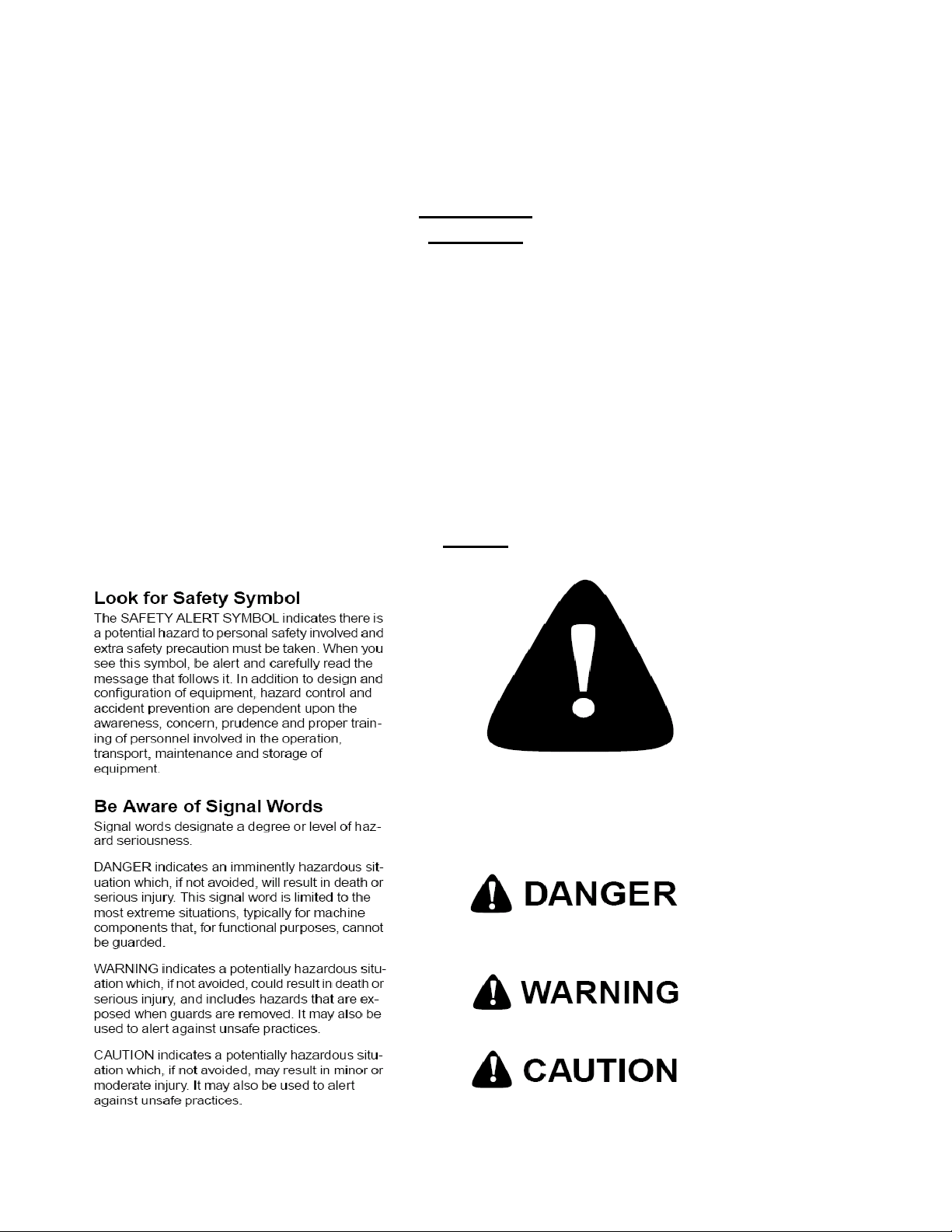
Safety
1-1
Page 3

Pub. #OM17-MSP3
Important! Read the following SAFETY PROCEDURES before operating the Veris system:
• Read and understand all instructions on safety decals
• Escaping fluid under pressure can penetrate the skin causing serious injury. Avoid the hazard
by relieving pressure before disconnecting hydraulic lines. Use a piece of paper or card-board,
NOT BODY PARTS, to check for suspected leaks.
• Wear protective gloves and safety glasses or goggles when working with hydraulic and highpressure wash systems.
• If an accident occurs, see a doctor immediately. Any fluid injected into the skin must be surgically
removed within a few hours or gangrene may result.
• Pinch point hazard: to prevent injury, stand clear when raising or lowering any part of the Veris
implement.
• Install all transport locks before transporting or working underneath.
• Detach and store implements in an area where children normally do not play. Secure implement
by using blocks and supports.
• Read Operations Manual before operating machine
• Review safety instructions with operators before operating machine and at least annually
• Never stand on or use tire as a step
• Do not tow the implement on public roads without the road-kit light package, or without the proper
safety equipment and licensing as required by your State Department of Transportation. Always
use safety chain.
• Riders obstruct the operator’s view. They could be struck by foreign objects or thrown from the
machine.
• Never allow children to operate equipment.
• To prevent possible electrical shock, or damage to the instrument, do not connect to any power
source greater than twelve (12) volts DC.
• Do not grease or oil implement while it is in operation.
• Disk edges are sharp. Be careful when working in this area.
• Disconnect battery ground cable (-) before servicing or adjusting electrical systems or before
welding on implement.
• Remove buildup of mud, oil or debris.
• Be very careful when mapping stubble fields with a gasoline engine vehicle. Be prepared if a fire
starts.
• Keep a first aid kit and fire extinguisher handy.
1-2
Page 4

Excess speed, especially when turning could cause overturning.
Never pull units faster than 15 km/hr.
Use caution when working on implement. Coulter disks are sharp and may
causes cuts.
Don’t allow anyone to climb or ride on implement
The vehicle that pulls the Veris unit thru the field will get hot! There is a chance that
this heat can cause field fires in stubble fields.
Don’t lower unit while any part of body is underneath
Pub. #OM17-MSP3
1-3
Page 5

Pub. #OM17-MSP3
Keep safety chain installed
Install jack before unhitching; do not drop unit on foot
FCC NOTE
This equipment has been tested and found to comply with the limits for a Class A digital device,
pursuant to Part 15 of the FCC Rules. These limits are designed to provide reasonable protection
against harmful interference when the equipment is operated in a commercial environment. This
equipment generates, uses, and can radiate radio frequency energy and, if not installed and used
in accordance with the instruction manual, may cause harmful interference to radio
communications. Operation of the equipment in a residential area is likely to cause harmful
interference in which case the user will be required to correct the interference at this own expense.
1-4
Page 6

Pub. #OM17-MSP3
EUROPEAN DECLARATION OF CONFORMITY
Veris Technologies, Inc., located at 601 N. Broadway in Salina Kansas, certifies that the product:
Veris MSP3
is in conformity with the following directive and standards:
Machinery Directive 2006/42/EC--1st Edition—December 2009
Electromagnetic Compatibility 2004/108/EC —December 2004
EN55022 – Measuring Radiated Emissions
The Technical File is maintained at:
Veris Technologies, Inc.
601 N. Broadway
Salina KS 67401
Date of issue: May 1, 2012
Place of issue: Salina KS USA
1-5
Page 7

Pub. #OM17-MSP3
Statement of Use
Intended use of the Veris MSP3 model
The Veris MSP3 Soil EC, Organic Matter, and pH Mapping System collects geo-referenced soil
electrical conductivity (EC), soil reflectance, and soil pH measurements as it is pulled across a field
by a tractor. An electronic device called the Soil EC Surveyor, powered by vehicle’s 12V DC
electrical system, generates a small electrical current, which is transferred into the soil through a
pair of rolling electrode coulter disks. A second pair of disks measures the drop in voltage which is
proportional to the electrical conductivity of soil medium at a given location. Signal response is due
primarily to soil texture/grain size and soil salinity. Clay soils and soils with high salinity levels are
highly conductive, while coarser soils such as sand do not conduct well. Another electronic device
called the OpticMapper controller, powered by vehicle’s 12V DC electrical system, sends power to
an optical sensor which has two wavelengths of LEDs and measures the amount of light reflected
off the soil surface with a photodiode. The optical sensor is mounted inside a standard row planter,
with two discs to cut a furrow in the soil and two depth gauge wheels to keep the sensor at
constant depth. Signal response is due to soil color, darker soils are generally higher in Organic
Matter; while lighter soils are lower in Organic Matter. A final electronic device called the pH
controller, powered by vehicle’s 12V DC electrical and hydraulic system, measures soil pH using
two electrodes. The pH controller cycles the pH sampling shoe into the soil, where a soil core is
collected and brought up and pressed against the electrodes for a measurement. Once a stable
reading is measured, the sampling shoe moves down to collect another soil segment, and the
electrodes are washed off. This process is repeated every 20-30 seconds, as long as the operator
keeps the system engaged, and ground speed is received. The sampling shoe is controlled by
hydraulic solenoids, while the wash jets are powered by two 150 psi pumps. The system records
the data either on its own datalogger, or on a data recording device such as a laptop computer.
Ultimately, the data are displayed in a map format, and variable applications of crop production
materials, such as seed, fertilizer and other inputs are variably applied to the zones delineated on
the maps. The MSP3 system is designed for use in a farm field, and has no dynamic movement
unless vehicle is pulling it, or operator is manually activating switches, so guarding around soil
engaging components is not needed and would interfere with field operations. Unit should not be
operated when people are present in the field, as coulter disks are sharp and automated
movement could cause injury if contact occurs.
Misuse of the Veris MSP3 model
Misuses of the MSP3 model include operation with people in area, and pulling the system at an
excessive speed. In field position, this could result in poor data collection and possible tractor
overturning at extremely high speeds and sharp turns. In raised position, the chance of
overturning is increased, as the center of gravity is higher, so care must be taken to keep speeds
under 15 km/hr, and less when turning.
Abnormal use of the Veris MSP3 model
Abnormal use of the MSP3 model includes using it as a cart for carrying equipment, tools, or
people. Under no circumstances should anyone ride on the implement. Even though the
implement is similar in appearance to a tillage tool, such as a disk harrow, it was not designed for
that usage and should never be used for any purpose other than soil data collection.
1-6
Page 8
Pub. #OM17-MSP3
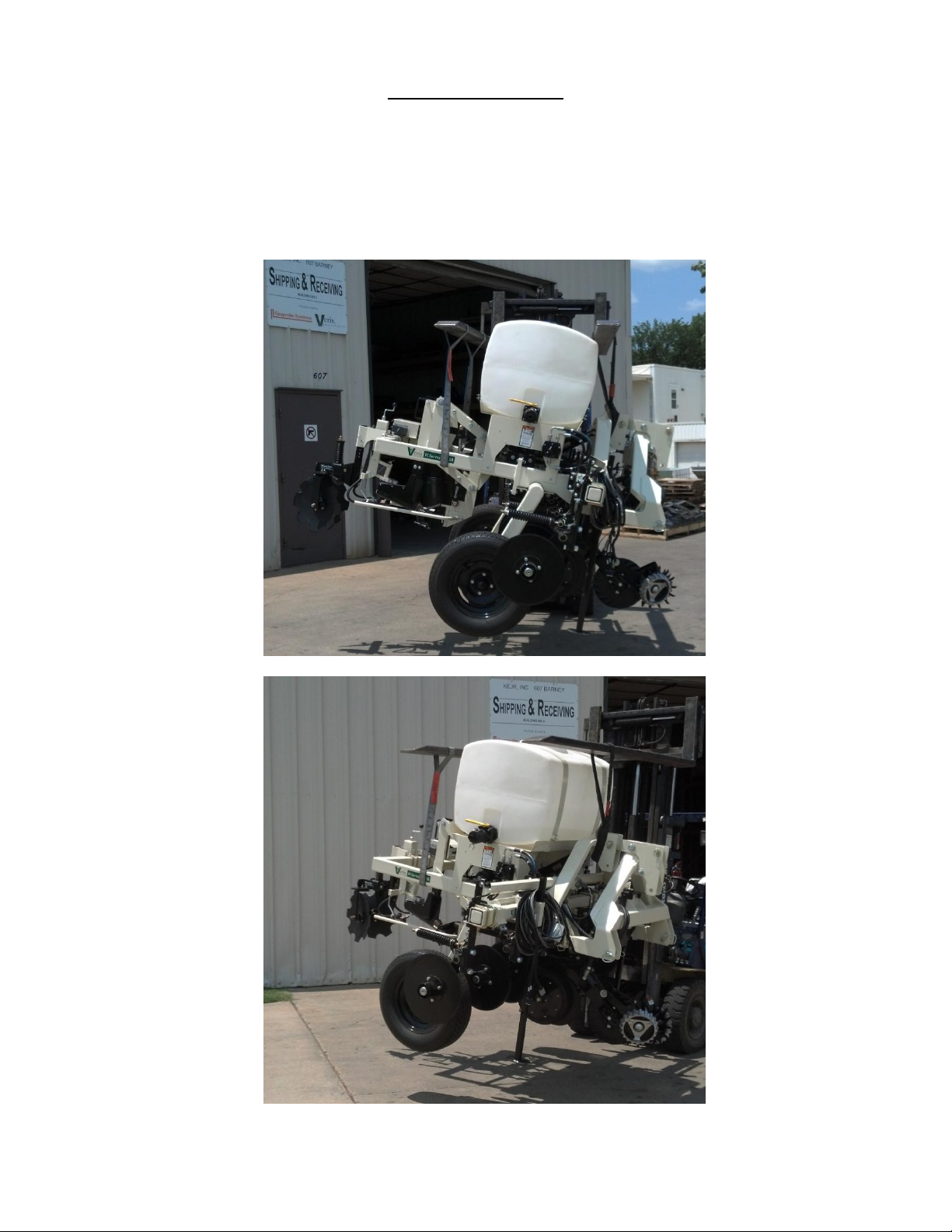
MSP3 Lifting Points
Below are the recommended lifting points for the unit. Using two straps you can safely lift the unit.
Make sure the straps used to lift are rated greater than 1200 lbs. Fork extensions maybe required
to lift. Always stay clear when lifting the unit.
Here are the proper lift points for side loading
1-7
Page 9
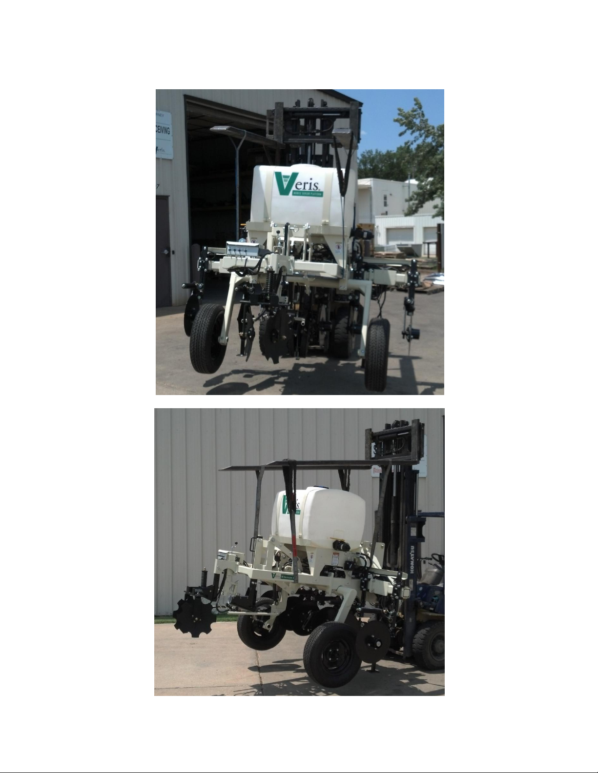
If lifting from front or back of the unit, use the points shown below.
Pub. #OM17-MSP3
1-8
Page 10
Section 2
USB Serial
Adapter
MSP3 EC
Test Box
pH
Simulator
Mounting
Bracket
OM
Reference
Block
OM test
load
MSP3 EC
test load
SoilViewer
Protective
Case
Three-way
power
adapter
DataLogger
SD card
reader
Power Cord
Figure 2
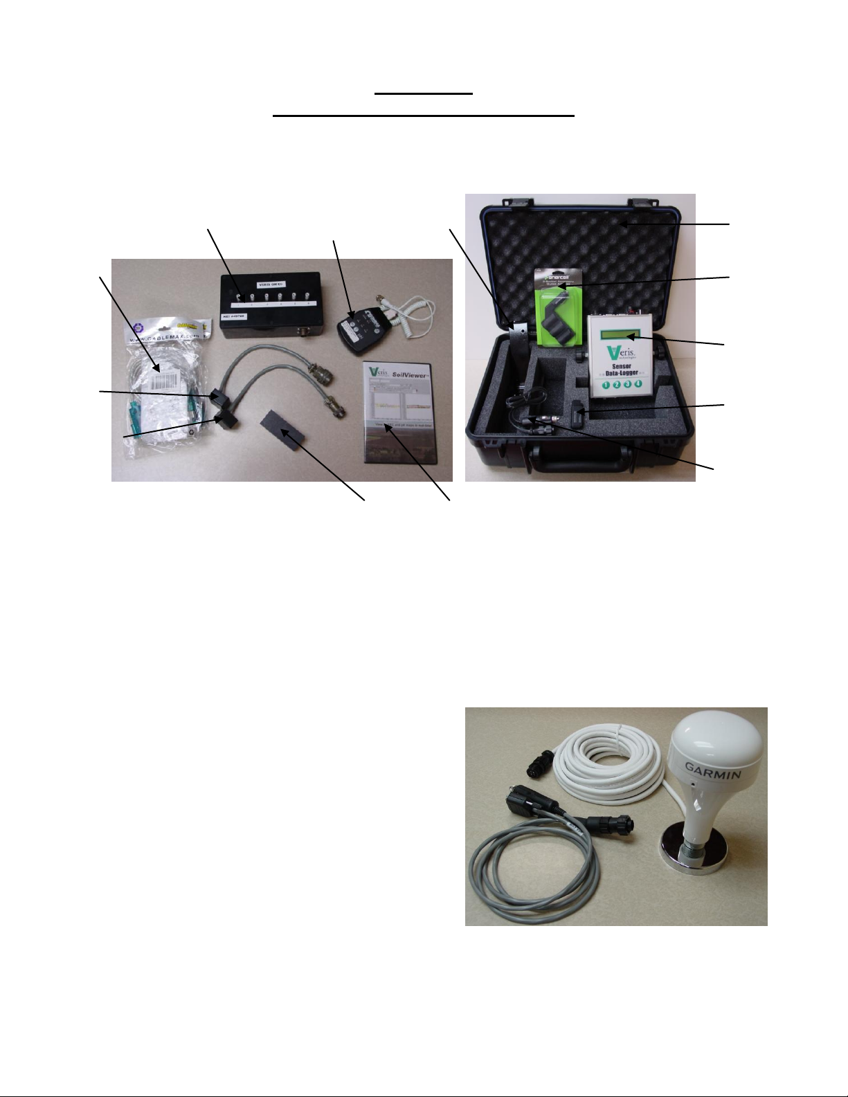
Electronics Overview and Set-up
The MSP3 electronics kit and optional DataLogger kit are shown below.
Pub. #OM17-MSP3
Figure 1a MSP3 electronics kit Figure 1b MSP3 DataLogger kit
Use protective shipping/storage case to protect electronics components whenever electronics are
shipped. Keep all diagnostics and operations manual with system when mapping.
Mount electronics in a location that is as free as possible from dust, vibration, and electrical
interference. Display should be visible to operator and shielded from direct sunlight. ‘
The supplied GPS(Figure 2) is configured to operate
with the MSP3 electronics.
The use of any other GPS requires the correct
settings. The GPS needs to output only two NEMA
strings(GGA and VTG OR RMC). The system will
not run with more than two strings. The strings
need to output at 4800 baud and 1Hz refresh rate.
2-1
Page 11
Pub. #OM17-MSP3
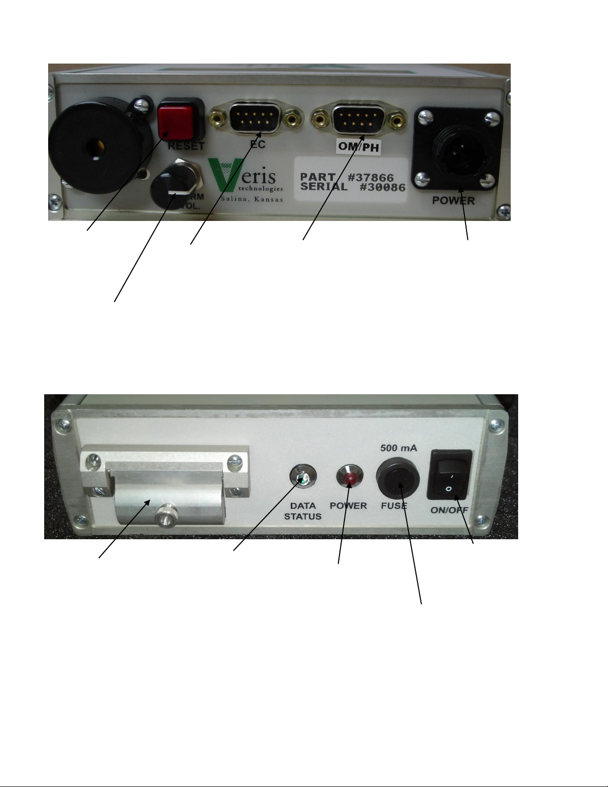
Data Status:
When lit, this green LED
indicates data is being
recorded to memory
card. If not lit, EC values
are negative or GPS
signal not received.
Power:
When lit, this red LED
indicates Sensor
DataLogger is
powered up.
On/Off:
Turns power to Sensor
DataLogger on and off.
Memory Card slot:
Formatted SD memory card
must be installed when
booting up, and at all times
data is being collected. See
Proc. #6 for formatting
instructions.
EC:
Serial cable from
EC/OM controller
attaches here.
OM/pH:
Serial cable from pH
controller attaches
here.
Reset button:
Can be used to
reboot
DataLogger
Alarm Vol:
Used to adjust volume
of auditory alarm
Fuse:
This allows the fuse to be
replaced, with a 500mA
Fastblow fuse, if blown.
Power port:
The Sensor DataLogger is shipped with an
accessory power cord. If an alternative
connection is desired, make sure that the
unit is properly connected to a power
connection that is not controlled by the
ignition switch. If connecting directly to the
battery, we suggest a 3-amp in-line fuse is
installed between the battery and the
instrument.
Figure 3 DataLogger (rear)
Figure 4 DataLogger (front)
Important – Do not allow moisture to enter the DataLogger, and do not pass strong magnets
near the unit.
2-2
Page 12
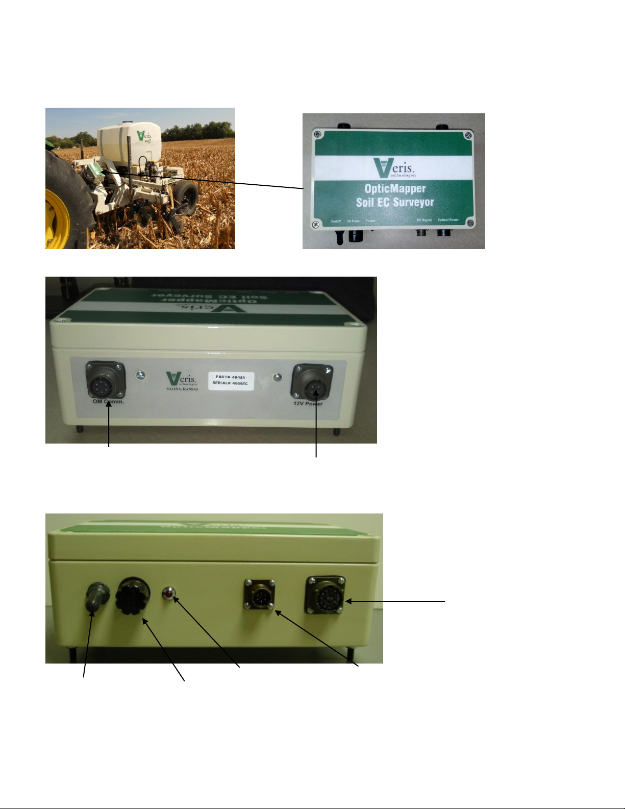
Pub. #OM17-MSP3
12V Power
Power cord shipped with the unit that
connects to the vehicle’s battery
On/Off
Turns power to
OpticMapper
Controller On/Off
3A Fuse
Power Indicator
Indicates when power
to the controller is on
Optic Power
Delivers power to
Optical sensor with
cable #46222
EC Signal
Connects to EC
wire harness with
cable #49457
OM Com/GPS Input
Serial communication to Datalogger or
PC and GPS input with cable #49494
The OpticMapper Controller is mounted on the implement, and can remain on the implement due
to weatherproofing.
Figure 5 OpticMapper Figure 6 OpticMapper/EC Controller
Figure 7 OpticMapper Controller (rear)
Figure 8 OpticMapper Controller (front)
2-3
Page 13
Pub. #OM17-MSP3
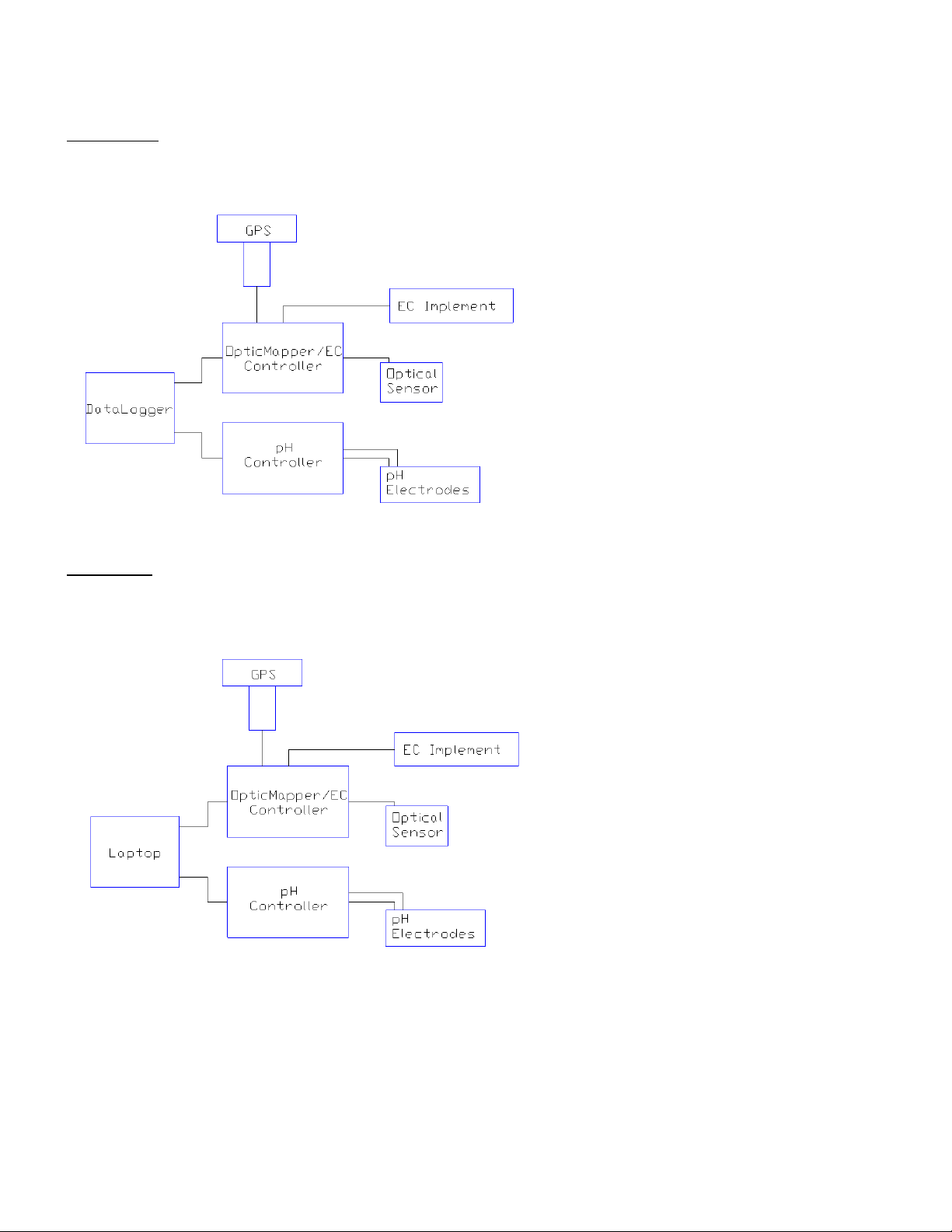
Electronic Configurations
Datalogger – Attach the OpticMapper/EC Controller communication cable to the EC port on the
Datalogger, then the communication cable from the pH Controller to the pH port. Connect EC
signal cable, GPS, and power cords to the OM/EC controller.
Figure 9
Soilveiwer – Connect both communication cables from OpticMapper/EC Controller and from the pH
Controller to Laptop using the supplied USB to Serial converters. Connect EC signal cable, GPS,
and power cords to the OM/EC controller.
Figure 10
2-4
Page 14
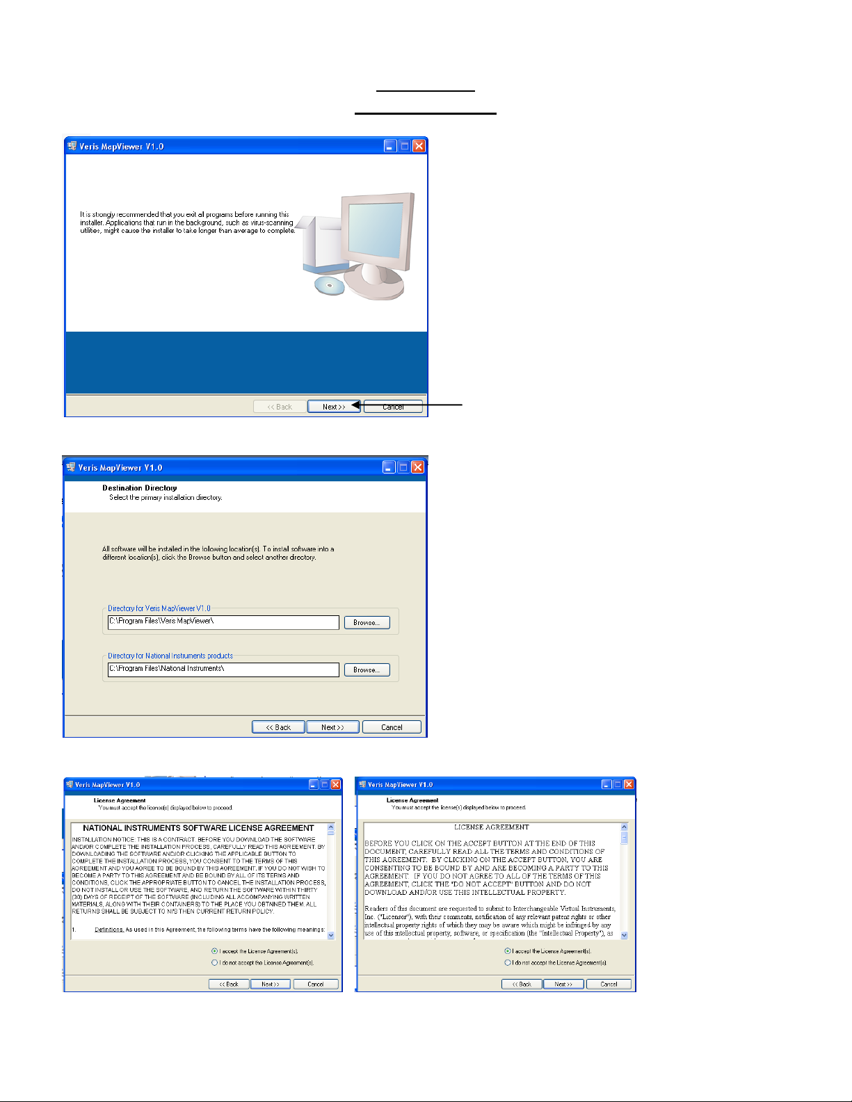
Figure 11
The Veris SoilViewer software will
automatically run the setup once the CD
is inserted into the computer. If not the
installation can be manually started by
double clicking on the setup.exe located
on the CD.
Once the CD has begun select the
installation directory and click Next
Click Next to continue through
installation
Next two license
agreements will need
to be accepted
before continuing.
Pub. #OM17-MSP3
SoilViewer
Software Setup
Figure 12
Figures 13a and 13b
2-5
Page 15
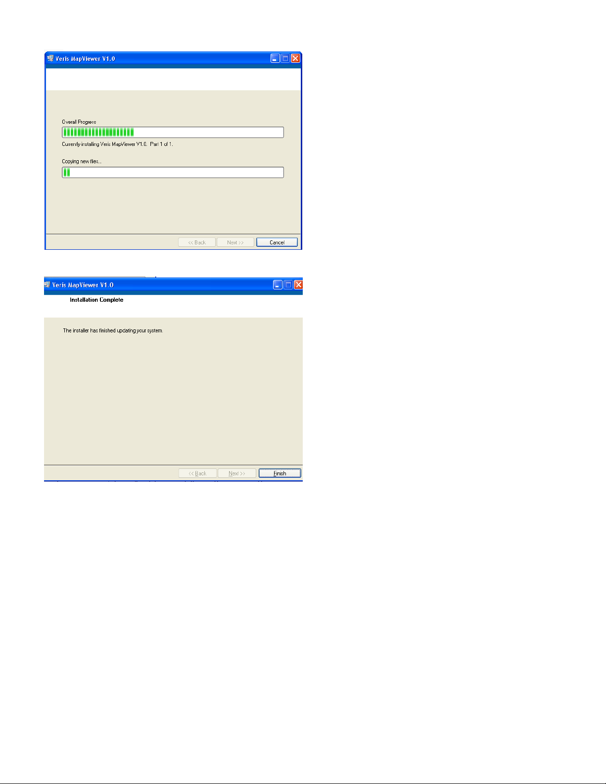
Figure 14
The installer will
install all necessary
components
Once the installer is completed, click
finish
Pub. #OM17-MSP3
Figure 15
2-6
Page 16
Pub. #OM17-MSP3
Section 3
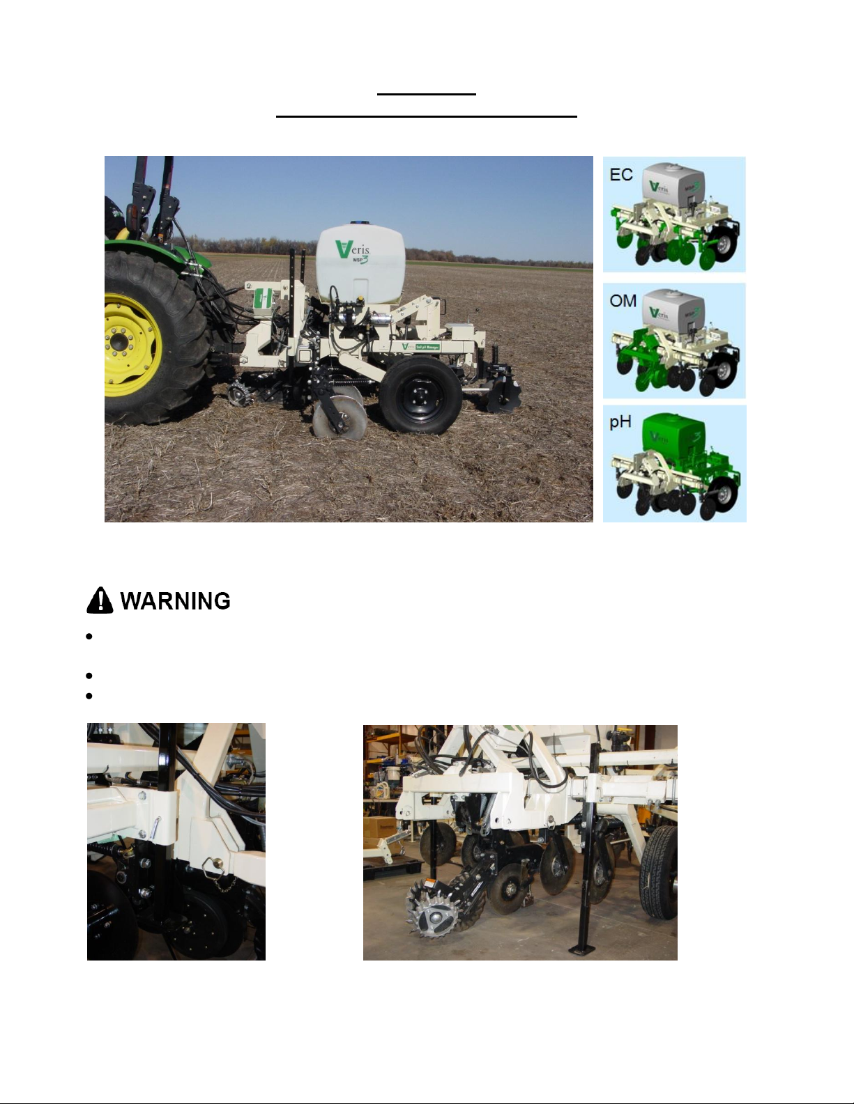
Implement Overview and Set-up
Figure 1 MSP3 with EC, OM, and pH sensor modules
Pinch point hazard: to prevent injury, stand clear when raising or lowering any part of the
Veris MSP3.
Install all transport locks before transporting or working underneath.
Always use the service stands when working underneath the MSP3.
3-1
Page 17
Pub. #OM17-MSP3
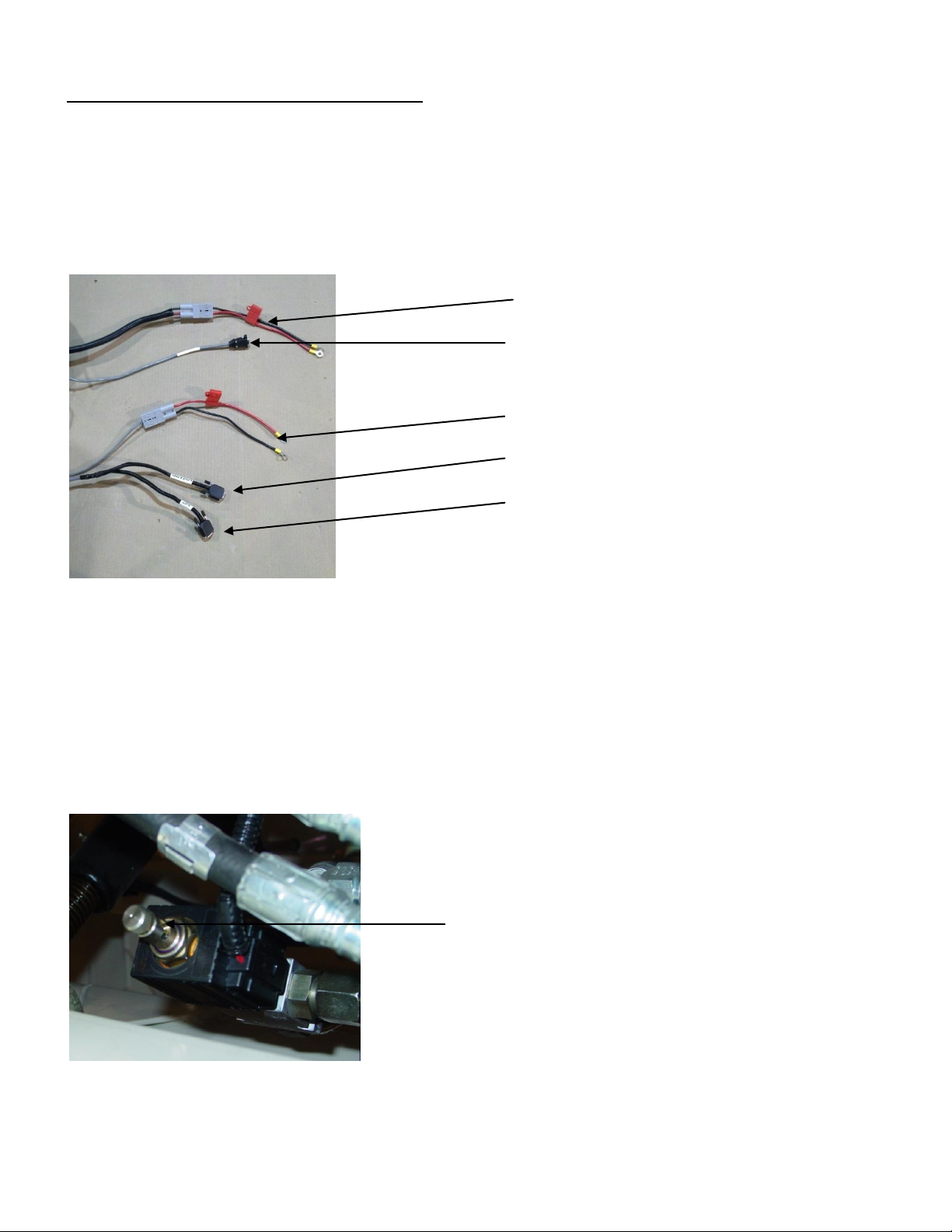
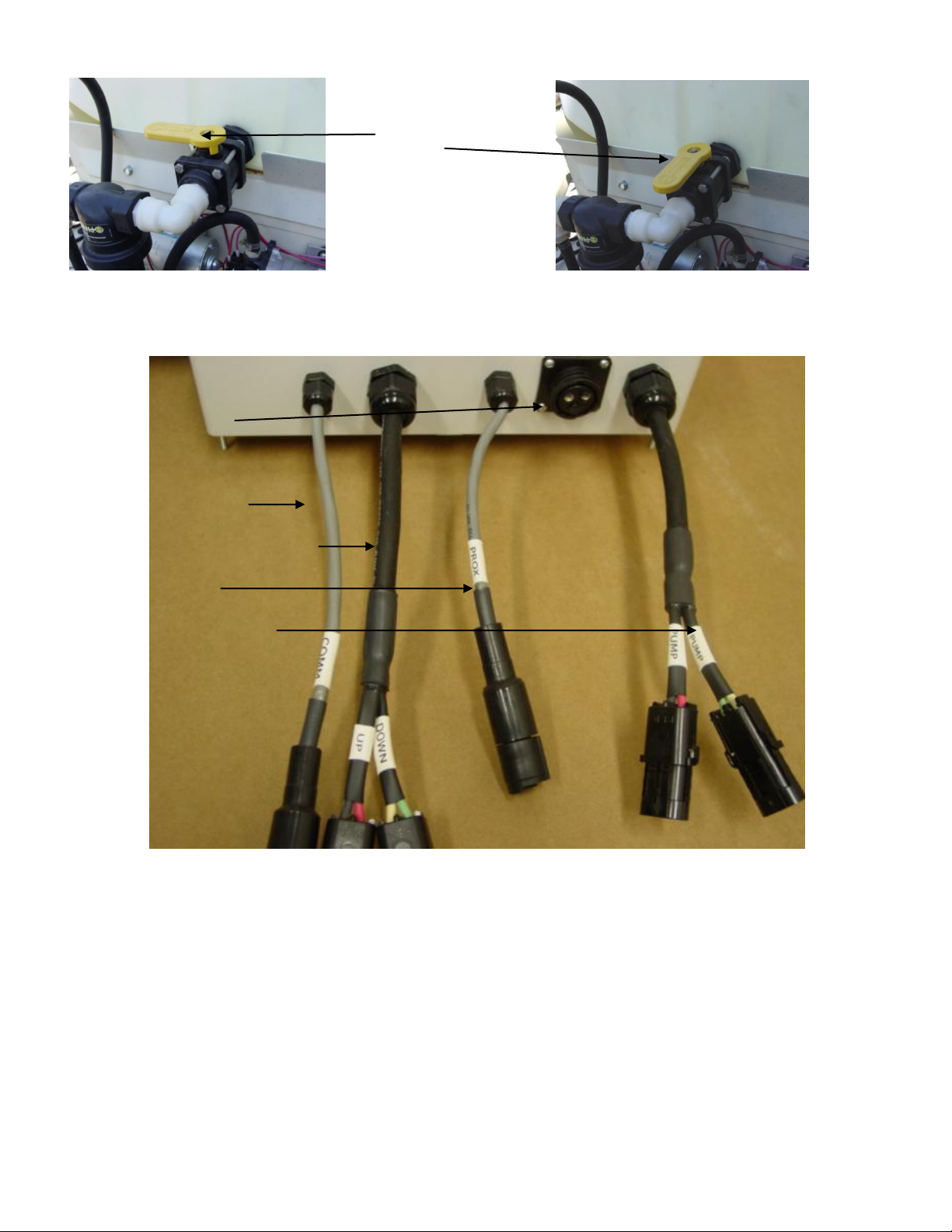
pH 12 V Power leads
pH com cable
Open/Closed center hydraulic poppet valve
-Up (out) for open center tractor hydraulics
-Down (in) for closed center tractor hydraulics
OM 12 V Power leads
OM com cable
GPS Input
12 Volt Power and Hydraulics Set-up
If the unit has been crated and delivered via closed-van commercial freight, the tongue (if
equipped) may need to be installed prior to use. Prior to operating the implement for the first time,
it is important to check all fasteners – some may have loosened during shipment. Route cables
and hydraulic hoses along tongue and through hose guide. Tie-strap securely. Connect electrical
cables to battery. Be careful to attach black cable to negative/ground terminal. DO NOT
REVERSE POLARITY.
Figure 2
Insert hydraulic ends into quick-couplers, being careful to insert the end marked “P” into the tractor
extension coupler, and the end marked “T” into the tank or return line coupler; in this configuration,
tractor’s hydraulic lever will be secured in raised position. If sampler shoe operates in reverse,
simply reverse hydraulic hoses, or secure lever in lowered position. Note: Be certain whether
tractor or hydraulic power source utilizes open or closed-center hydraulics. Damage to
tractor could occur if not set properly. The poppet knob is set ‘up’ for open systems, and
‘down’ for closed-center systems – (see settings below.) Press down and turn knob to lock down—
press down, turn and release to allow it to move up to open position.
Figure 3
3-2
Page 18
Pub. #OM17-MSP3
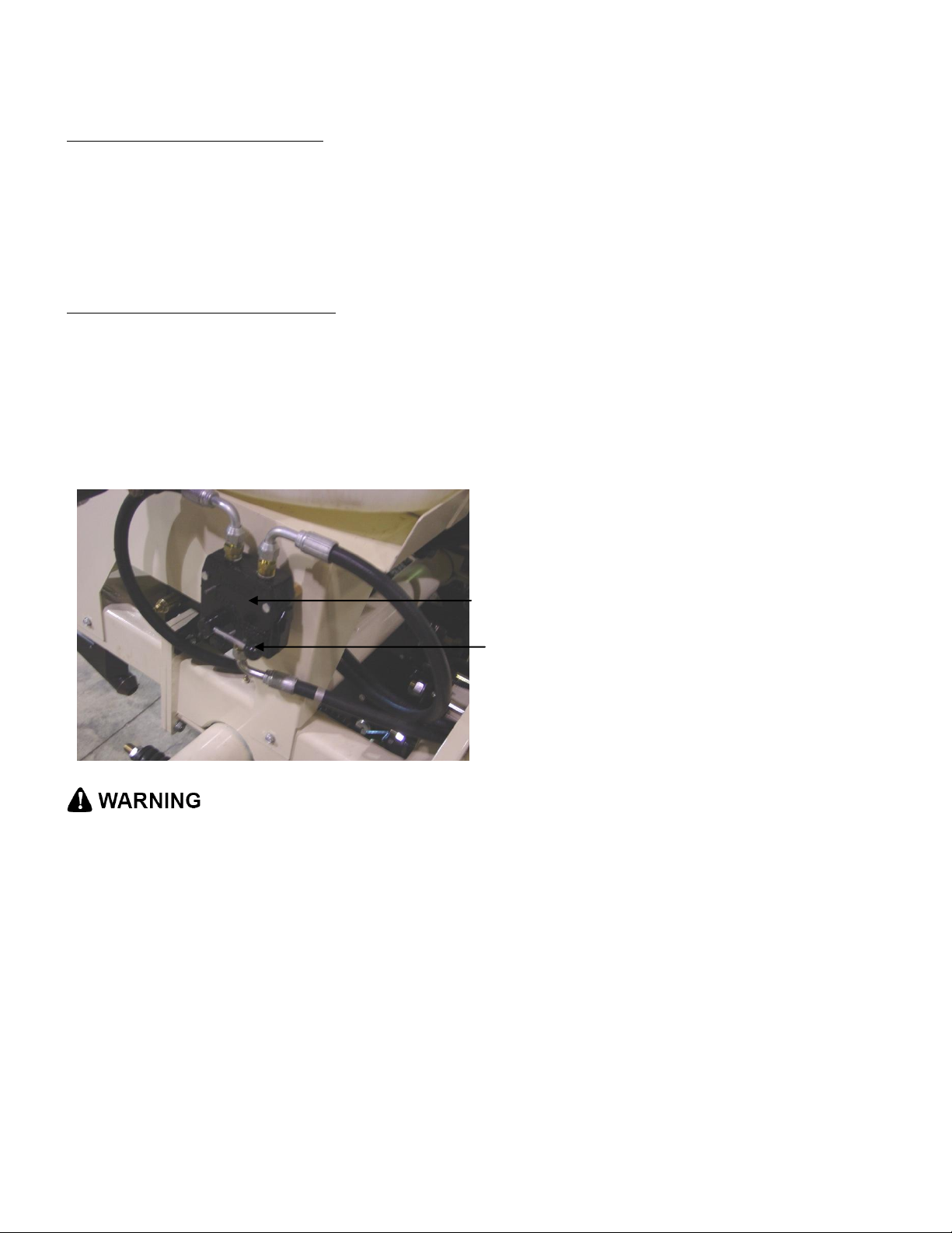
Flow control settings:
Open center hydraulic systems
1) Set poppet valve in “up” raised position, this allows flow back to tank
2) Set engine at field rpm
3) Set pH controller to “Manual” and run sampling shoe up and down, timing the cycle time.
4) If sampler raises in approximately 1.5 -2 seconds, leave flow control as is, if not, adjust control
arm upward or downward to achieve desired speed.
Closed center hydraulic systems
1) Set poppet valve in down position. Push down and rotate so that rolled pin locks into closed
position. This blocks flow and allows the pump to de-stroke when the directional valve is in
the neutral position.
2) Adjust flow control valve to full open position.
3) Set engine at field rpm.
4) Run sampling shoe upward and adjust raise time to approximately 1.5-2 seconds using
throttling valve on tractor’s remote coupler
Note: Excessive sampling shoe speed can
damage electrodes.
Flow control valve
Adjustment control arm
Figure 4
• Escaping fluid under pressure can penetrate the skin causing serious injury. Avoid the hazard
by relieving pressure before disconnecting hydraulic lines. Use a piece of paper or card-board,
NOT BODY PARTS, to check for suspected leaks.
• Wear protective gloves and safety glasses or goggles when working with hydraulic and highpressure wash systems.
• If an accident occurs, see a doctor immediately. Any fluid injected into the skin must be surgically
removed within a few hours or gangrene may result.
Flush and fill tanks with tap water; clean any foreign matter out of tank using ball valve clean-out.
Set ball valve to open position, allowing water to flow to pumps.
3-3
Page 19
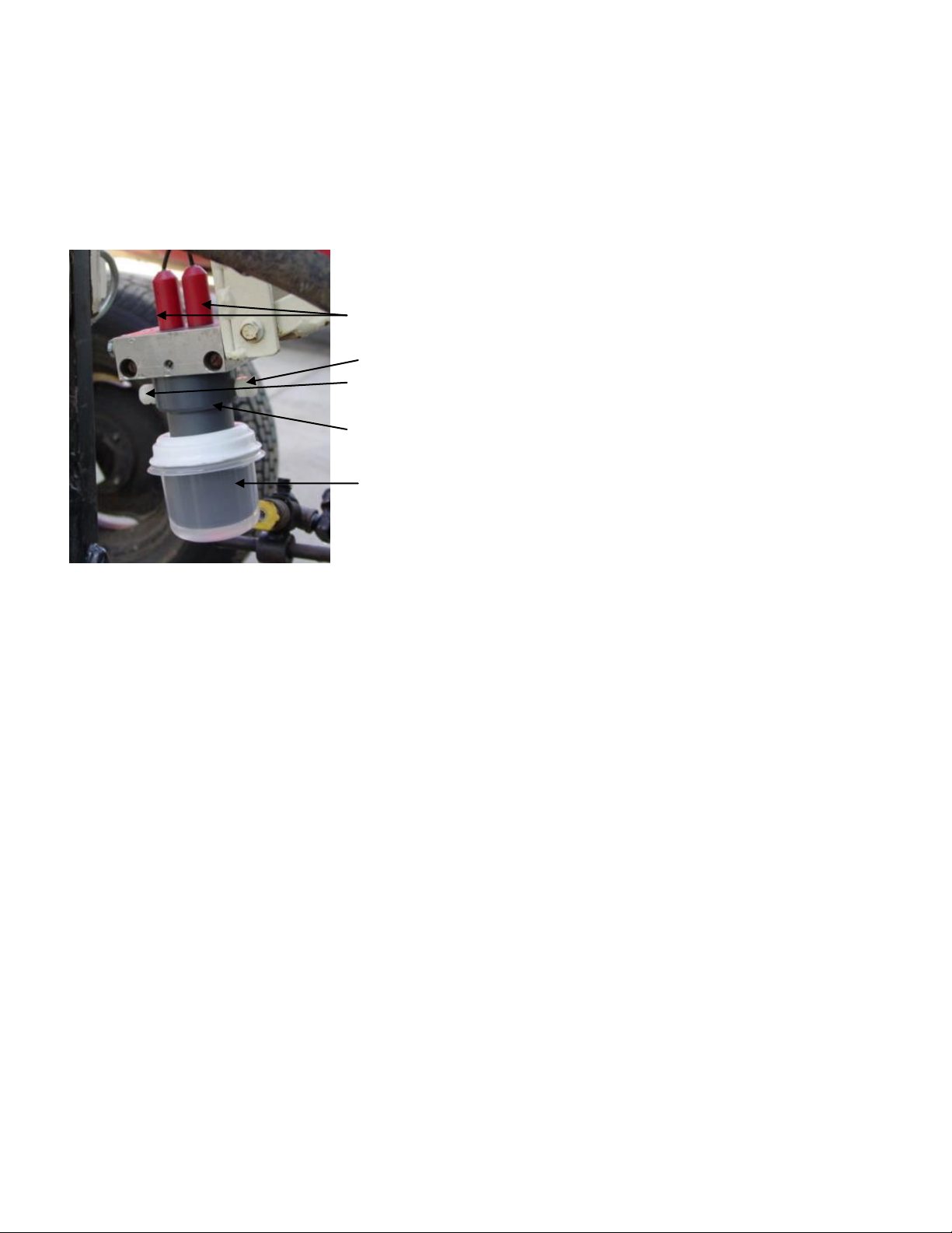
ball valve:
closed
open
12 V power in
Communication
Sampler solenoid power
Prox sensor
Wash pump power
Figures 5a and 5b
Connecting cables to External controller as shown below:
Pub. #OM17-MSP3
Figure 6
3-4
Page 20
Pub. #OM17-MSP3
pH
electrodes
electrode set
screws and
lock nuts
electrode
holder
soaker cup
Remove pH electrodes from individual storage containers and fill soaker solution cup with soaker
solution. Install soaker solution cup on electrode holder. Loosen plastic set screws on electrode
holder and insert pH electrodes into electrode holder. Re-tighten set screws finger tight and lock in
place with lock nuts. Do not overtighten set screws or electrode damage may occur. Always keep
electrodes in soaker solution, either in individual containers or soaking in large cup installed over
electrode holder. Route electrode cables away from sampling mechanisms to prevent damage—
tie-strap excess length of cable as needed.
Figure 7
3-5
Page 21
Pub. #OM17-MSP3
Section 4
Field Operations: DataLogger: OM and pH System Checks
Sensor DataLogger display readings
Here are the display readings shown when operating the Sensor DataLogger:
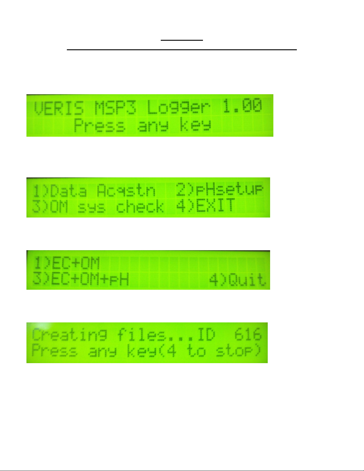
Starting up…
Figure 1
The unit is ready to operate. The DataLogger is informing you of the firmware version its
programmable interface chip (PIC) contains.
Press any of the four keys, and the next screen will appear:
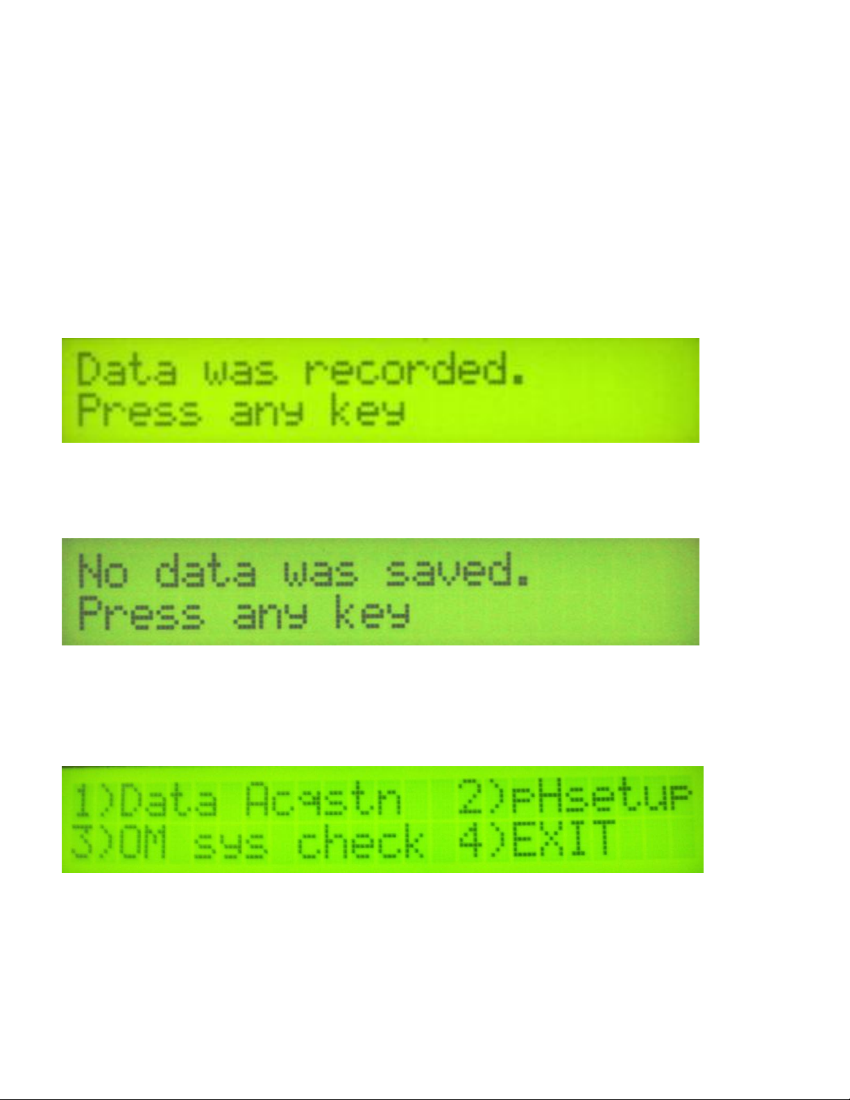
Figure 2
For Mapping, press the #1 key. For OM System check press the #2 key (page 4-4). #4 Exit
returns you to the initial start-up screen. Pressing #1 brings up the next screen:
Figure 3
For EC and OM mapping, press the #1 key. For EC, OM and pH press the #2. #4 Exit returns you
to the initial start-up screen. Pressing #1 or #2 brings up the next screen:
Figure 4
The DataLogger is displaying the map file number it is creating, in case you want to record it along
with any other information about the field. Press any key to begin new map file. After starting the
file, pressing the #4 key will stop the file. If DataLogger freezes at the screen shown in Figure 6 or
Figure 7, check formatting of SD card—must be FAT format. See Proc. #6 for formatting
instructions.
4-1
Page 22
Pub. #OM17-MSP3
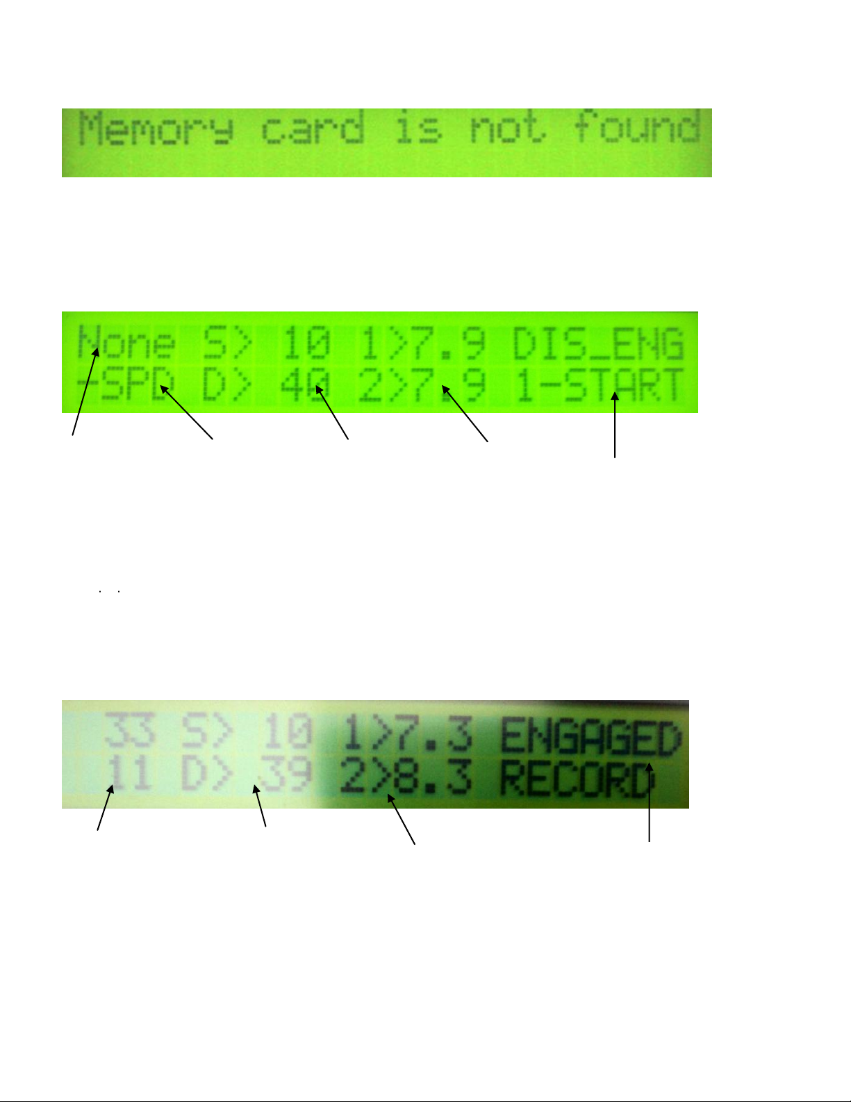
Ground
speed (from
GPS) in
miles/hour
GPS status: may
read GPS,
DGPS, RTK, or
None. If None, no
GPS signal is
received and no
data will be
Shallow (S)
and Deep (D)
soil EC
readings. If
negative, no
data will be
recorded.
pH sampler status
pH readings from
electrodes 1 and
2
OM reflectance
readings the top
is RED the
bottom is IR
Shallow (S) and
Deep (D) soil EC
readings. If
negative, no data
will be recorded.
pH readings
from electrodes
1 and 2
pH sampler status
If memory card was not inserted during boot-up, the following screen will appear:
Figure 5
Install card and re-start DataLogger. NEVER REMOVE CARD WHILE LOGGING DATA.
This is the Data Acquisition screen with GPS status (note:GPS status will blink every second when
engaged to show the OM readings):
Figure 6
Figure 7 The acquisition screen with OM readings
4-2
Page 23
Pub. #OM17-MSP3
There are warning signals programmed into the Veris DataLogger to warn the operator that data is
not being recorded, so that corrective action can be taken. If data is not being recorded, a warning
alarm will sound, and the portion of the screen text that is missing information will blink. For
example, if the DGPS isn’t being received (or the NMEA string containing speed) the Lat/Long text
will blink. If EC values are negative, they will blink. Also, the Data Status LED light on the front of
the DataLogger indicates whether data is being recorded. If this light is not lit, data is not being
recorded. (note: no data is recorded unless unit is moving—receiving speed signal from GPS)
At any time during the mapping process, you can press any key to stop the file. If you create more
than one file from the same field, you can bring the files into a spreadsheet program or GIS and
combine for whole field map display.
After #4 key is pressed during Data Acquisition, the following screen will be displayed: (if data
was collected during Data Acquisition)
Figure 8
DATA IS ONLY STORED ON THE SD CARD. NO INTERNAL FILES ARE CREATED.
If no data was logged during Data Acquisition, the following screen will be displayed:
Figure 9
Sensor DataLogger OM System Check
Here are the display readings shown when operating the Sensor DataLogger while running OM
system check:
Figure 10
4-3
Page 24
Pub. #OM17-MSP3
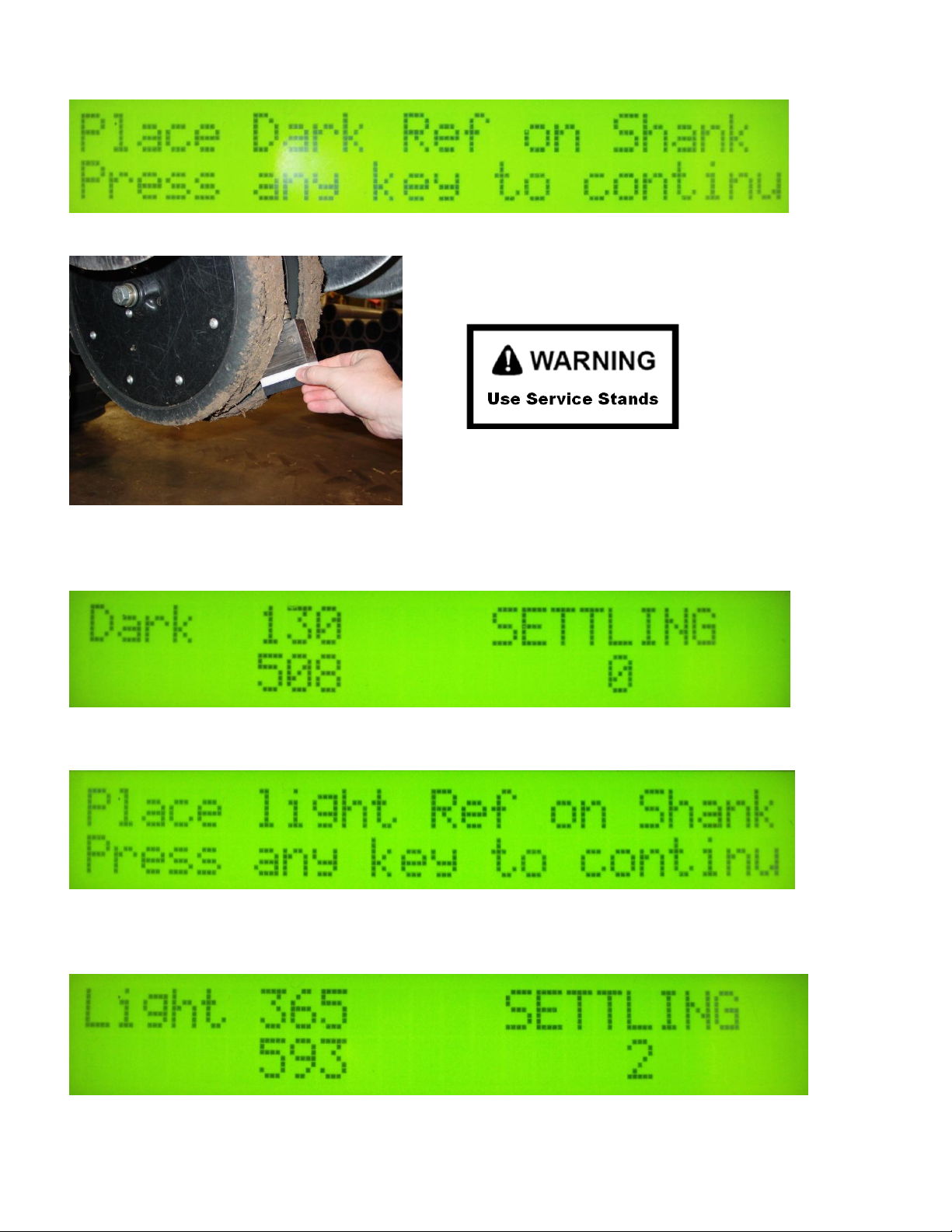
Press #3 to continue with OM System check:
Figure 11
Figure 12
If the window is clean and in good condition (see 4-8), attach the dark side of the Reference to the
sensor. (Figure 12) Press any key to continue:
Figure 13
After the readings have settled the next screen will appear:
Figure 14
Turn the Reference block over and attach the light side of the Reference to the sensor. (Figure 12)
Press any key to continue:
Figure 15
4-4
Page 25
Pub. #OM17-MSP3
After the light reference has been read, the following will appear:
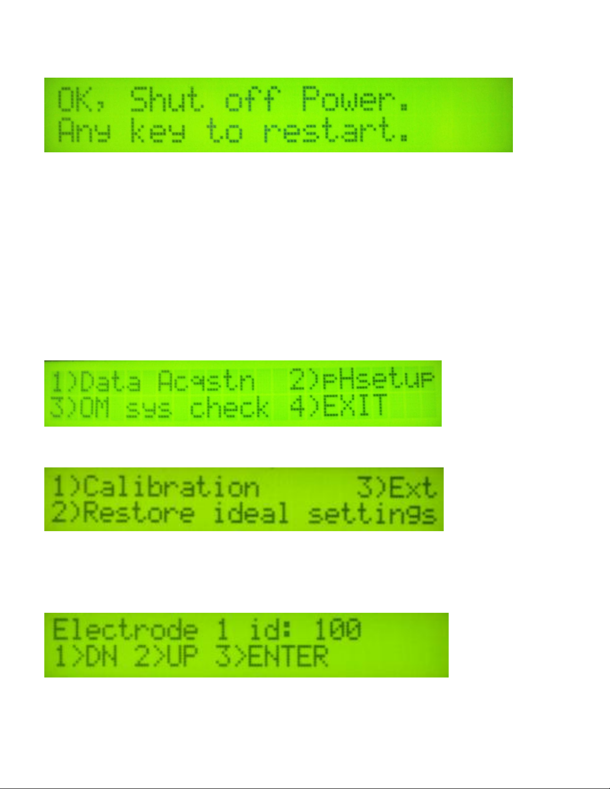
Figure 16
The reference data has now been stored. Once the system is restarted it is ready to start
mapping.
*NOTE: To ensure system is operating correctly always run a system check before
mapping a field.
There should be a difference of 100 or greater from dark reference to light reference for
each wavelength.
pH System Check
Calibrating pH electrodes
Enter menu option 2) pHsetup
Figure 17
Enter menu option 1) Calibration.
Figure 18
You will be asked for the ID of the electrode connected to channel 1. You may want to add an ID
number to the electrodes, for your own tracking purposes. Use the 1 and 2 keys to change the
number and 3 to confirm:
Figure 19
Repeat for electrode 2’s ID and press 3 to confirm.
4-5
Page 26
Pub. #OM17-MSP3
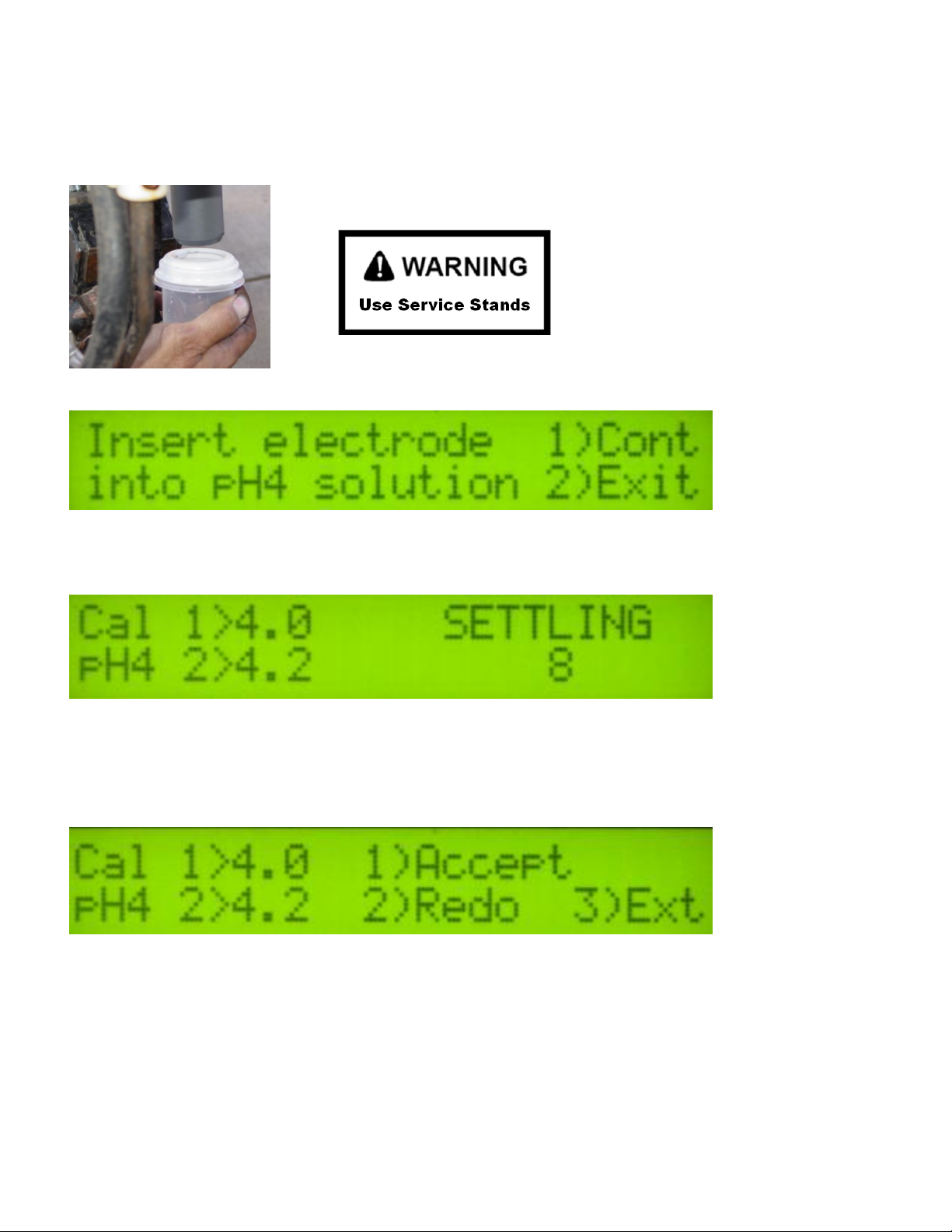
The instrument will prompt for the electrodes to be inserted into pH buffer 4 solution; Slide cup with
pH 4 buffer solution onto electrode holder. Press 1 to continue with calibration or 2 to exit. Tips:
Don’t overfill solution. Cup only needs enough solution to immerse electrode tip and face. Don’t
reuse solutions.
Figure 20
Figure 21
The instrument will read the electrodes for 10 seconds, displaying the output (as it counts
seconds):
Figure 22
After 10 seconds, the instrument will display the final pH reading and offer the options to 1) Accept
pH 4 buffer readings; 2) Redo pH 4 buffer readings; or 3) Exit pH electrode calibration. If the
readings are satisfactory, press 1; if the readings are suspect, press 2 to return to re-do pH 4.
Figure 23
After accepting the pH 4 buffer readings, the Instrument will prompt for the electrodes to be
inserted into pH 7 buffer solution. Remove the pH 4 buffer solution cup from the electrode holder.
Rinse the electrodes, electrode holder, and solution cup using the manual wash for at least 10
seconds. Slide the pH buffer 7 solution cup onto the electrode holder.
4-6
Page 27
Pub. #OM17-MSP3
On the DataLogger, press 1 to continue with calibration. The DataLogger will read the electrodes
for 10 seconds, displaying the output. After 10 seconds, the instrument will display the final pH
reading and offer the options to 1) Accept pH 7 buffer readings; 2) Redo pH buffer 7 readings; or 3)
Exit pH electrode calibration. If the readings are satisfactory, log pH 7 reading and press 1; if the
readings are suspect, press 2 to return to pH 7 calibration step.
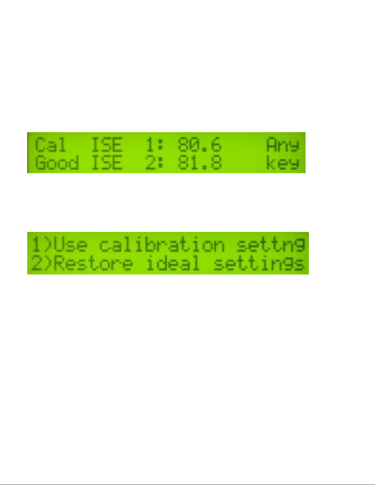
After accepting the pH 7 buffer readings, the electronics firmware will determine if each electrode’s
response is sufficient to provide suitable readings. A score is displayed for each electrode; the
acceptable score range is between 75 and 102. If both electrodes are within this range, the
instrument will display the following screen:
Figure 24
If an ‘X’ is displayed beside one or both electrodes’ scores, this indicates that one or both of the
electrodes did not perform well enough for continued reliable use. No calibration settings are
changed if calibration is unsuccessful. The electrode(s) responsible for failed calibration should be
removed and either cleaned or replaced and the calibration procedure repeated.
Figure 25
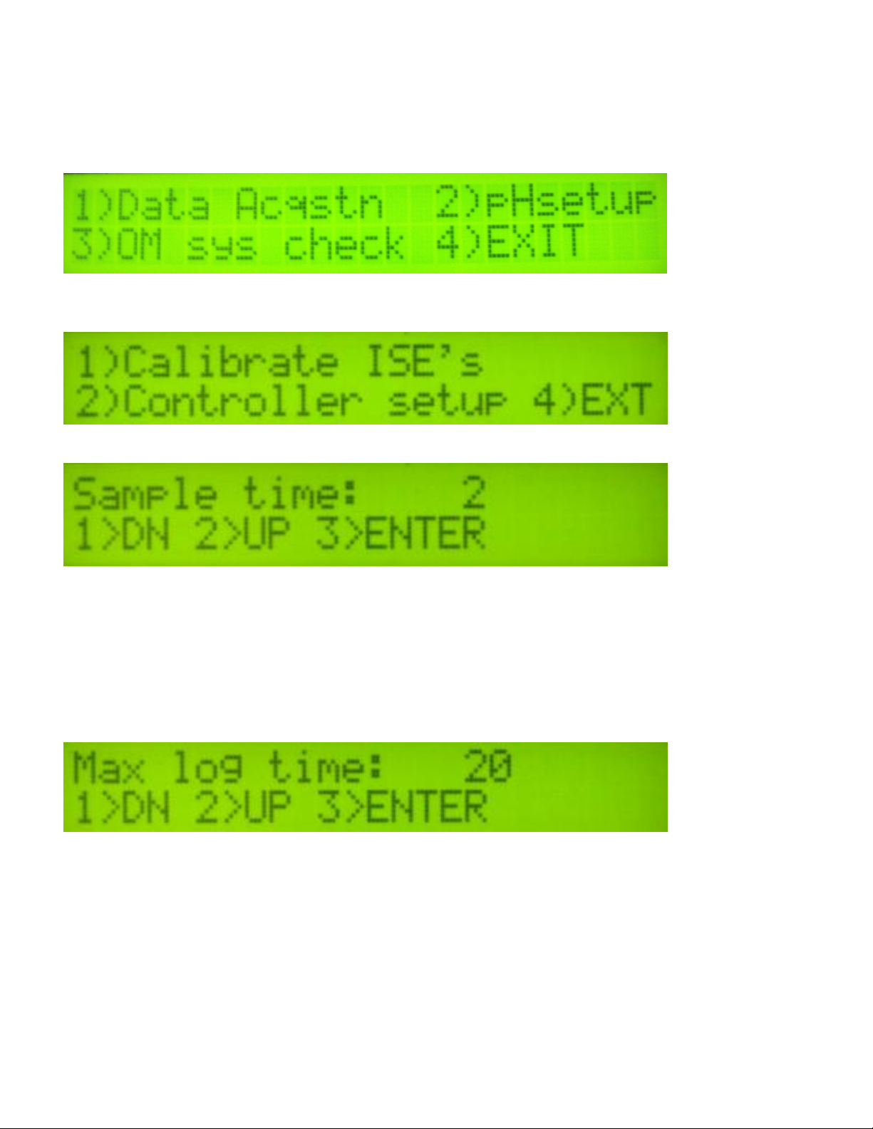
After calibration is complete, you will have the option to use the calibrated readings or reset to the
ideal settings. Tip: many operators use the ideal settings rather than calibration settings. One
reason is this enables readings from one day to be compared to another. It is still important to
perform the calibration step at least daily, even if ideal settings are used. The calibration process
is important to test electrode quality.
4-7
Page 28
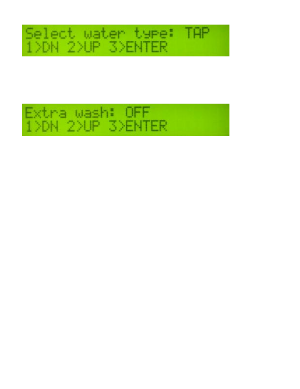
pH Controller Set-up
After calibration, you may wish to change the pH Controller default parameters.
Enter menu option 2) pHsetup
Figure 26
Enter menu option2) Controller setup
Figure 27
Pub. #OM17-MSP3
Figure 28
Sampling time is the duration that the sampler assembly is in the soil. Typically 2 seconds is
adequate. In soil conditions that do not produce a firm core, this time may need to be set at 3
seconds in order to allow soil to begin flowing through cutting shoe. If soil conditions result in a
very firm core, the sampling time may be reduced to 1 second. In rocky conditions, use 1 second
sample time to reduce likelihood of sampler shoe damage. Press 1 or 2 to adjust the sample time,
press 3 to continue to the next screen.
Figure 29
Maximum log time is the longest time in seconds the pH controller will wait for the pH readings to
settle. The controller usually cycles before this maximum time is reached. The minimum setting
for the maximum log time is 20 seconds. (Tip: use 20 seconds unless there is a special reason to
allow a longer wait time) Press 1 or 2 to adjust the sample time, press 3 to continue to the next
screen.
4-8
Page 29
Pub. #OM17-MSP3
Figure 30
Select the type of water you are using to clean the electrodes between samples. The available
types are TAP, RO (reverse osmosis), or DI (de-ionized). Press 1 or 2 to cycle through the water
types, press 3 to continue to the next screen. Tip: If you don’t want a baseline wash performed
every 40 cycles, use RO setting rather than Tap or DI (regardless of actual water being used).
Figure 31
Turning on the extra wash option will add 1.5 seconds of cleaning per cycle. The extra wash is
performed by stopping the shoe briefly during the cycle. Use this feature if you have noticed the
electrodes are not cleaning during the cycle. Press 1 or 2 to choose ON or OFF, press 3 to
continue. Tip: water usage will double if extra wash is used.
4-9
Page 30

EC – EC Surveyor connected to PC
OM – OpticMapper and GPS connected to PC
pH – pH controller and GPS connected to PC
EC and pH – EC Surveyor and pH controller
connected to PC
EC and OM – EC Surveyor and OpticMapper
connected to PC
EC OM pH-MSP3 – OpticMapper/EC Controller and
pH controller connected to PC
To acquire EC, OM and
pH data select Acquisition
Figure 32
Pub. #OM17-MSP3
Field Operations: SoilViewer: OM and pH System Checks
Figure 33
To acquire data with the MSP3 only EC OM pH- MSP3 can be used. This is the only option that
will work with the MSP3. This will allow the user to collect all three sensor readings, or collect only
EC and OM if desired.
4-10
Page 31

Pub. #OM17-MSP3
After clicking on EC OM
pH- MSP3 the user will
be prompted to input the
EC file name. All OM
and pH files will be
named the same as the
EC. Files may be
appended to by
selecting a previously
created VSEC file.
The EC OM pH-MSP3 Mapping software will automatically detect which ports the Veris
OpticMapper /EC Controller and pH Controller are connected to, and begin communicating. If
either is not detected, the software will wait 45 seconds for the connection of the electronics and
search again; this will repeat until both instruments are connected. If the electronics are not found,
unplug the serial or USB cables and reconnect them to the PC. If the connections are still not
made, refer to SoilViewer troubleshooting. The conditions for mapping and storing the data are as
follows. The user must be going a speed greater than 1 mph, there must be a GPS signal
received that includes position and speed (GGA and either VTG or RMC), the OM/EC Comm Light
must be green, indicating the PC and OpticMapper with EC Surveyor are communicating properly,
and either of the EC values has to be greater than -1.
Before mapping, run the OM system check and pH calibration to ensure everything is
operating correctly. pH controller settings can be modified to adjust the wash and cycle
times for specific field conditions.
Figure 34
Pinch point hazard: to prevent injury, stand clear when raising or lowering any part of the
Veris MSP3.
Install all transport locks before transporting or working underneath.
Always use the service stands when working underneath the MSP3.
4-11
Page 32

Pub. #OM17-MSP3
SoilViewer OM System Check
The OM System check ensures the optical sensor and controller are functioning properly. By using
the light and dark reference block the range of the sensor can be determined. For proper
operation the range from the dark to light side for the red and IR readings must be at least 100. If
it is not that may indicate a broken wearplate, inadequte power, or damaged sensor. Run the
system check before mapping each field to ensure proper operation. The results of the system
check are stored in a .inf file specific for each field.
Click the OM System Check button to start system check.
Figure 35
After clicking the System Check button the following will
appear:
Figure 36a and 36b
Make sure the window is clean and in good condition. (see 4-8) Place the dark side of the
reference block under the window, and click continue. The following message will appear.
Figure 37
Turn the reference block over to the light side and place under the window, and click continue.
Either of the following messages will appear:
Figure 38a and 38b
4-12
Page 33

pH System Check: Calibrating pH electrodes
You will be asked if you want to
continue the calibration or restore
ideal settings.
Click on Calibrate ISE’s or press F1
Figure 39
Figure 40
Pub. #OM17-MSP3
Figure 41
You will be asked for the ID of the electrode connected to channel 1. You may want to add an ID
name or number to the electrodes, for your own tracking purposes. Insert the name or number
then press OK to continue.
Figure 42
4-13
Page 34

Pub. #OM17-MSP3
The software will prompt for the electrodes to be inserted into pH buffer 4 solution; Slide cup with
pH 4 buffer solution onto electrode holder. Press 1 to continue with calibration or 2 to exit. Tips:
Don’t overfill solution. Cup only needs enough solution to immerse electrode tip and face. Don’t
reuse solutions.
Figure 43
The software will read the electrodes for 10 seconds, displaying the output (as it counts seconds):
Figure 44
After 10 seconds, the software will display the final pH reading and offer the options to Accept pH 4
buffer readings; Redo pH 4 buffer readings; or Cancel pH electrode calibration. If the readings are
satisfactory, press Accept; if the readings are suspect, press Redo to return to re-do pH 4.
Figure 45
4-14
Page 35

Pub. #OM17-MSP3
After accepting the pH 4 buffer readings, the software will prompt for the electrodes to be inserted
into pH 7 buffer solution. Remove the pH 4 buffer solution cup from the electrode holder. Rinse
the electrodes, electrode holder, and solution cup using the manual wash for at least 10 seconds.
Slide the pH buffer 7 solution cup onto the electrode holder.
Figure 46
Press continue to proceed with the calibration. The software will read the electrodes for 10
seconds, displaying the output. After 10 seconds, the software will display the final pH reading and
offer the options to Accept pH 7 buffer readings; Redo pH buffer 7 readings; or Cancel pH
electrode calibration. If the readings are satisfactory, log pH 7 reading and press continue; if the
readings are suspect, press redo to return to pH 7 calibration step.
After accepting the pH 7 buffer readings, the software will determine if each electrode’s response
is sufficient to provide suitable readings. A score is displayed for each electrode; the acceptable
score range is between 75 and 102. If both electrodes are within this range, the software will
display the following screen:
Figure 47
If an ‘X’ is displayed beside one or both electrodes’ scores, this indicates that one or both of the
electrodes did not perform well enough for continued reliable use. No calibration settings are
changed if calibration is unsuccessful. The electrode(s) responsible for failed calibration should be
removed and either cleaned (See section 5-7) or replaced and the calibration procedure repeated.
Figure 48
After calibration is complete, you will have the option to use the calibrated readings or reset to the
default parameters. Tip: many operators use the default parameters rather than calibration
settings. One reason is this enables readings from one day to be compared to another. It is still
important to perform the calibration step at least daily, even if ideal settings are used. The
calibration process is important to test electrode quality.
4-15
Page 36

Pub. #OM17-MSP3
pH Controller Set-up
After calibration, you may wish to change the pH Controller default parameters. Press Controller
Setup or F3 and enter Setup menu.
Figure 49
Figure 50
The pH sampler settings can be adjusted without exiting the current file. Additionally, a correction
can be applied to each electrode’s pH shown on the screen. Occasionally, the pH readings shown
on the screen may differ from those expected in the field. If this is the case, the pH shown on the
screen can be adjusted up or down with the pH offset 1 and pH offset 2.
The offset is adjustable in 0.5 pH increments up to +/- 2.00 pH. NOTE: The instrument DOES
NOT apply this offset to the extracted file. Only the readings seen on the screen will be affected.
Sampling time is the duration that the sampler assembly is in the soil. Typically 2 seconds is
adequate. In soil conditions that do not produce a firm core, this time may need to be set at 3
seconds in order to allow soil to begin flowing through cutting shoe. If soil conditions result in a
very firm core, the sampling time may be reduced to 1 second. Press the up and down arrows to
adjust the sample time.
4-16
Page 37

Pub. #OM17-MSP3
Log time is the longest time in seconds the pH controller will wait for the pH readings to settle. The
controller usually cycles before this maximum time is reached. The minimum setting for the log
time is 20 seconds. Press the up or down arrows adjust the sample time. (Tip: use 20 seconds
unless there is a special reason to allow a longer wait time)
Select the type of water you are using to clean the electrodes between samples. The available
types are TAP, RO (reverse osmosis), or DI (de-ionized). Tip: If you don’t want a baseline wash
performed every 40 cycles, use RO setting rather than Tap or DI (regardless of actual water being
used).
Turning on the extra wash option will add 1.5 seconds of cleaning per cycle. The extra wash is
performed by automatically stopping the shoe briefly during the cycle. Use this feature if you have
noticed the electrodes are not cleaning during the cycle. Put a checkmark in the box to turn the
extra wash on and uncheck to turn off the extra wash. Tip: water usage will double if extra wash is
used.
4-17
Page 38

Pub. #OM17-MSP3
Field Operations—EC and OpticMapper
Tools required for Field Operation adjustments
-3/8”, 7/16”, 1/2” 9/16” 3/4” 15/16” wrench
-9/16”, 3/4” 12point socket
-3/8” ratchet
-Ohm meter
Checking Electrical Signal Continuity and Electrode Isolation
It is recommended that you perform the Electrical Signal Continuity and Electrode Isolation test
procedure before first field use (see Maintenance and Service Procedures 1 and 2). While these
tests were made at the factory, there is the possibility a problem developed during shipping.
Performing these tests on the new implement before it becomes dirty, allows you to get familiar
with the process under ideal conditions. It is strongly advised that you perform this test on a routine
basis (every 10 hours of data collection) to ensure you are obtaining reliable data. KEEP
OHMMETER, TEST LOAD AND TEST BOX WITH THE MACHINE AT ALL TIMES.
Setting Operating Depth
Begin field operation by lowering unit into soil. For good electrical conductivity, all coulter
electrodes must be in direct contact with moist soil, at all times and in every region of the field. A
depth of 1-2” (2.5-5 cm) is recommended. To insure this depth is consistently achieved, 400-600
lbs. (180-275 kg) of additional weight are normally required. Carrying water in the pH wash tank
can aid penetration. Also, Veris offers optional weights, or they can be supplied by the customer.
Do not adjust the tension on the coulter electrode springs to increase soil contact or penetration.
They are pre-set at the factory with the proper tension.
Figure 51 Figure 52
4-18
Page 39

Pub. #OM17-MSP3
set screws and
jam nuts
Adjustable Wing Extensions
This feature allows the re-positioning of the electrodes to fit various bed and crop configurations.
Adjustment is made by loosening the jam nuts and set screws located on the lower front of each
side of the toolbar, adjusting the toolbar wing extensions, and re-tightening the set screws. Veris
suggests setting the toolbars at either the maximum or minimum setting, not at a point in between.
A limiter bolt determines full extension, so they cannot extend to the point at which the outside
coulters disconnect from the main frame. Important – do not attempt to combine maps in which two
different investigative depths are used.
Figure 53
Pinch point hazard: to prevent injury, stand clear when raising or lowering any part of the
Veris MSP3.
Install all transport locks before transporting or working underneath.
Always use the service stands when working underneath the MSP3.
Figure 54 Figure 55
4-19
Page 40

Top Link
3-point Adjustment
Turn the top link (Figure 60) to adjust the tilt and level the unit.
This is the optimal setting for all fields types. Extending the top
link will cause the rear of the unit to move down. Shortening the
top link will cause the inverse.
Row Unit Adjustment
Adjust side depth wheels on optical row unit to allow deeper or
shallower mapping. Move T-handle (Figure 61) backward for
deeper depth. Depth wheels should be snug, but freely moving,
against the disks. See Section 5-3 for more information.
Pub. #OM17-MSP3
Adjust spring pressure on row unit as needed. With implement
lifted to reduce pressure on springs, move handle forward to
reduce spring pressure and back to increase. Additional weight
may be required in hard soils. Reduce pressure in rocky
conditions to prevent damage to window. (Figure 62)
Row Cleaner Adjustment
The row cleaner needs to be adjusted for your
conditions, crop changes, and as coulters and
openers wear. Ideally, cleaners contact only the
trash, and do not disturb the soil.
To adjust row cleaner loosen bolts, 1, and slide
the down stop, 2, to the desired cleaning depth.
Forward for deeper cleaning and backward for
shallower cleaning.
Figure 63
4-20
Page 41

Pub. #OM17-MSP3
Coulter Adjustment
Adjusting the coulter depth is accomplished by re-mounting the coulter blade in one of the six
mounting holes arranged in a staggered pattern in the coulter bracket.
Figure 64
Raise unit and lower service stands before
working on coulters. Do not attempt to move
blade when the current or new position causes
it to contact the ground during the adjustment.
Be careful around the front end of row units.
Row cleaner tines and coulter blades may be
sharp.
To adjust coulter depth:
1. Determine the present opener and coulter
depths.
2. Note which bracket hole the coulter is
presently using.
3. Determine which new hole will position the
coulter closer to the 1/4in-above depth. See
the table below.
4. Remove the 5/8-11 x 4in bolt, lock washer
and nut ( A in Figure 64).
5. Move the blade to the new position. Insert
the bolt, and tighten on the lock washer and
nut.
6. Re-adjust row cleaners, if installed. If a
worn coulter cannot be adjusted to
satisfactory operating depth, replace coulter.
4-21
Figure 65
Page 42

Pub. #OM17-MSP3
Speed
Proper field operating speed depends on field condition. Because of the importance of consistent
contact, the unit must not be allowed to bounce over rough fields at high speeds.
Field Condition
Field should be in a uniform state. Mapping after intensive primary tillage is not recommended. The
soil must have a minimum of 20% available water, and cannot be frozen. If rocky conditions exist,
slow down and make sure rock guards are in place. Also if the field is rocky and/or muddy the
optical module will needs to be adjusted to make optimum contact with the soil, as well as
decreasing the chance for window breakage.
Swath width and Navigation
Setting the swath width and navigation system is at the discretion of the customer. A 50’-75’ (1523 m) swath works well in most areas. Several methods of navigation are possible: following
previous crop rows, swath guidance, or using a field navigation computer. While it is important to
map in a consistent pattern, it isn’t absolutely critical that each pass be exactly the same distance
from the previous pass.
4-22
Page 43

Pub. #OM17-MSP3
To help insure the quality of your data, please follow these guidelines:
1. Generate and view maps frequently, especially prior to deleting data from Instrument.
2. Listen for auditory alarm from DataLogger, indicating data collection has been interrupted.
3. View DataLogger screen or SoilViewer map frequently during data collecting; watch for:
Negative readings in the Shallow and Deep or excessive noise in the OpticMapper data.
Sensor readings should fluctuate gradually as you drive across the field, relating to
soil changes. If readings change erratically, or show values not typical of soil
in the area, perform tests 4-6 below.
In SoilViewer, watch for streaks, stripes, unnatural patterns, and missing data points.
4. Perform electrical continuity test on implement wiring:
at least once a day during mapping season
every 10 hours of mapping
after extended periods of non-use
after replacing or repairing coulter-electrode components or wiring
whenever readings are questionable
5. Perform Signal Testing Procedures #1 and #2:
at least once a day during mapping season
every 10 hours of mapping
after extended periods of non-use
whenever readings are questionable
6. Perform black/white reference OM System Check and OM Test Load Procedure #1
Before mapping every field
Whenever readings are questionable
7. Keep all electrical connections dirt and moisture-free
8. Limit speeds in rough or rocky field conditions. This will improve data quality, and will also
lengthen the service life of the implement components. NEVER EXCEED 15 M.P.H. FIELD
SPEED WHEN MAPPING EC/OM. NEVER EXCEED 7.5 M.P.H. WHEN MAPPING PH.
4-23
Page 44

Pub. #OM17-MSP3
OM Data Quality
Check depth of sensor – Make a couple of trial passes to make sure the sensor is running at the
proper depth. Recommended depth is 2-3 inches.
Add weights or adjust down pressure on row unit if needed
Also make sure the row unit side depth wheels and disks are rotating freely, and are clear of
excess mud and crop residue.
For row unit adjustments see page 4-22.
Monitoring the window –Observe OM readings at row ends when unit is raised, if they are not
within 10% of the initial raised readings, check windows for mud, smearing, and/or window
breakage.
Varying Field Conditions – In order to have high data quality the field conditions need to be the
same for an entire data set. Any of the following can affect data quality: in-field soil temperature
and moisture difference, change in down pressure or depth gauge wheel setting. If conditions
change, start a new file.
Figure 66 is an example of how these items can affect data quality.
4-24
Page 45

Pub. #OM17-MSP3
OpticMapper Wearplate
Below is a comparision of two wearplates. The left is a brand new wearplate, and the right has
about 2500 acres on it. Inspect the leading edge,shown below, as the steel wears the window can
chip or crack. As this contiunes to wear it will eventually need replaced.
Figure 67a & b
Wearplates will wear differently in every type of soil, so check it often. To replace wearplate refer
to Procedure #11
4-25
Page 46

Pub. #OM17-MSP3
Field Operation—pH Manager
Tools required for Field Operation adjustments
-3/16” allen wrench
-adjustable wrench: min. 10” (25 cm) length
-3/4” socket and wrench
-9/16” socket or wrench
-15/16” wrench
Pinch point hazard: to prevent injury, stand clear when raising or lowering any part of the
MSP3.
Install all transport locks before transporting or working underneath.
Always use the serivce stands when working underneath the MSP3.
Figure 68 Figure 69
4-26
Page 47

Pub. #OM17-MSP3
Power switch
must be on to
operate any
function
Manual-Auto switch:
must be in Automatic
mode for mapping;
in Manual mode for
manual control of
washing or sampler
shoe position
Sampler up and down:
raises sampler shoe
manually
Wash: On when washing
manually; Must be Off
for Automatic washing
Manually Operating Wash and Cycling Functions
After all cables and hydraulic hoses are connected, test power to unit by turning external pH
controller power switch to on position. With control switch in manual position, run wash pump
briefly. If water does not flow from jets within 10 seconds, disconnect quick couplers to help pumps
prime. If water doesn’t spray, but pump is running, see Troubleshooting section for instructions on
priming pump. If pumps don’t operate, recheck power cables and connections. If electrical power
to Controller is functioning, test hydraulics by locking hydraulic lever in position, and raising and
lowering sampler shoe using manual Up/Down switch. Test Raise/Lower functions on main lift
cylinder if equipped. Make sure no one is under unit and keep clear of any pinch points.
Figures 8a and 8b
Figure 70
4-27
Page 48

Pub. #OM17-MSP3
Operate implement parallel
to soil or slightly tipped (up
to ½”) forward never allow
unit to tip backward --this will
decrease shoe penetration.
Begin with a
dimension of
21” pin to pin
Adjust tractor or
implement top link to
level
Initial adjustment of
21”
Three-point Mounted Units
Raise sampling mechanism to full height. Begin depth adjustment process with shank in center
position (pin in one of two center holes). Adjust ratchet jack so that coulters will penetrate 1-2”
deep – 21” pin-to-pin is a good starting point Adjust three-point top link to level unit when in soil.
Figure 71 a,b,c
Figure 72
4-28
Page 49

Pub. #OM17-MSP3
pull adjustment pins and
lower shank if deeper
sampling is needed (and
EC coulter depth is
satisfactory)
sampling depth
is measured
from top of
cutting shoe to
soil surface
Once unit is level, lower sampling mechanism completely, drive forward 10-20’ (3-6 m) to create
soil core. To measure depth of soil core being collected, brush away soil from cutting shoe.
Measure from soil surface to top of cutting shoe. This is the depth of sampling. To increase
sampling depth, shorten ratchet jack; to decrease sampling depth, lengthen ratchet jack. Releveling unit with adjustable top link may be required.
Figure 73
Note: if MSP is equipped with EC Module and EC data is being collected along with pH data,
adjusting the overall height of the unit will affect coulter-electrode depth. If deeper soil sampling is
desired, and shortening ratchet jack would result in excessive coulter-electrode depth, remove
sampler shank pins and lower shank to lowest setting. If shallower soil sampling is required, and
lengthen ratchet jack results in inadequate coulter-electrode depth for EC data collection, raise
sampler shank to highest setting.
Figure 74
Once EC coulter depth and sampling depth are satisfactory, adjust other components in this
sequence:
1. Scraper adjustment: in manual mode hydraulically raise the sampling shoe to maximum height.
Adjust scraper until cutting shoe clears scraper blade when sampler shank is fully raised.
4-29
Page 50

Pub. #OM17-MSP3
Turn crank to raise
or lower electrode
holder
electrode
holder 1”
(2.5cm)
above wash
jets
Adjust scraper bracket
until cutting shoe
clears scraper when
sampler assembly is
raised completely.
½” (1.2 cm) clearance
between electrode holder
and trough liner
Figure 75
2. Adjust electrode holder: with sampling mechanism raised completely, adjust electrode
holder to provide ½” (1.2 cm) clearance between it and sampling trough.
Figures 76a and 76b
3. Wash adjustment: Wash brackets should be parallel to sampling trough, with jets directly
beside electrode holder, jets should be 1” (2.5 cm) below electrodes; when electrodes are
properly aligned.
Figures 77a and 77b
4-30
Page 51

Pub. #OM17-MSP3
Closing Disks
depth adjustment
pin
Closing disk
angle
adjustments
When wash jets are
properly aligned,
overspray is minimized
and water bubbles out
top of empty electrode
holder as shown here.
When installing BNC cover, route
electrode wires under box; center box
on white pad, and tighten wingnut finger
tight. Keep cover installed even when
electrodes are removed.
Figures 78a and 78b
4. Insert pH electrodes into electrode holder. Finger-tighten plastic screws. Install BNC cover
on external controller to keep moisture out of BNC connectors. Leave BNC cover on
whenever unit is outdoors.
5. Row cleaner/coulter: Pull MSP forward and check depth of row cleaner and coulter.
Cleaner should be clearing residue ahead of sampling shoe, but not gouging into soil.
6. Closing disks (if equipped): Adjust closing disks as needed to properly close trench and
bring residue over row-cleaned zone. Do not operate these deeper in soil than necessary.
Figures 80a and 80b
4-31
Page 52

Pub. #OM17-MSP3
1/4 to 3/8” gap
7. Prox sensor: The prox sensor communicates the position of the sampler assembly to the
external controller for automatic cycling functions. Adjust sensor to 1/4”- 3/8” (6-9 mm) gap.
Cycle unit manually to insure that this gap is maintained throughout cycling range. Red
LED light should light whenever prox sensor is near metal and not light when away from
metal. To view LED light, shade ambient light from prox sensor and cycle sampler
assembly manually. Be careful to not strike or damage prox sensor face. NOTE: in manual
mode, hydraulic cylinder opens and closes completely; in automatic mode cylinder stops as
soon as prox sensor clears upper and lower plate. In order for cylinder to set electrodeshoe clearance properly (step 2 above), adjust prox sensor height with sampler shoe
completely raised. Adjust the prox sensor so it barely clears the lower part of the sensor
plate when sampler is completely raised. It may be necessary to reposition the electrode
holder after adjusting prox sensor; see step 2 above.
Figure 81
Figure 82
4-32
Page 53

Pub. #OM17-MSP3
Mapping with Veris Datalogger
Connect EC signal cable and power cords to ports on rear of OpticMapper/EC Controller, connect
the GPS to the GPS in of the OM Comm. cable, then connect the serial output of the OM Comm.
to the EC port on the DataLogger. Attach the pH controller to the pH port on the datalogger.
Press any button to continue
Figure 83
Press 1)Data Acqstn
Figure 84
Press 3)EC+OM+pH
Figure 85
Press any key to continue
Figure 86 The DataLogger is displaying the map file number it is creating, in case you want to
record it along with any other information about the field. Press any key to begin new map file.
After starting the file, pressing the #4 key will stop the file. If DataLogger freezes at the screen
shown in Figure 86, check formatting of SD card—must be FAT format.
If memory card was not inserted during boot-up, the following screen will appear:
Figure 87
Install card and re-start DataLogger. NEVER REMOVE CARD WHILE LOGGING DATA
4-33
Page 54

Pub. #OM17-MSP3
Ground speed
(from GPS) in
miles/hour
GPS status: may
read GPS, DGPS,
RTK, or None. If
None, no GPS signal
is received and no
data will be
recorded.
Shallow (S) and
Deep (D) soil
EC readings. If
negative, no
data will be
recorded.
pH sampler status
pH readings
from electrodes
1 and 2
OM reflectance
readings the top
is red the
bottom is IR
Shallow (S) and
Deep (D) soil
EC readings. If
negative, no
data will be
recorded.
pH readings
from electrodes
1 and 2
pH sampler status
This is the Data Acquisition screen with GPS status (note: GPS status will blink every second when
engaged to show the OM readings):
Figure 88
The acquisition screen with OM readings (note: GPS status has changed to show the OM
readings) The Datalogger will change from OM reflectance readings to GPS during mapping
Figure 89
The display is showing the pH values from the pH electrodes, conductivity of the top 1’ (30 cm) and
top 3’ (90 cm) of the soil, and whether you have GPS or DGPS or OM(differentially corrected)
signal. At any time during the mapping process, you can press the 4 key to stop the file. If you
create more than one file from the same field, you can bring the files into a spreadsheet program
and combine them prior to mapping. Note: the #1 key toggles the pH sampler from engaged to
disengaged; the #4 key stops the file.
From this screen, pressing the 1 key as you drive forward will initiate the automatic sampling
process. The software requires movement indicated by the GPS receiver in order to cycle.
Speed must be detected within 5 seconds after pressing 1 or the system will disengage.
If TAP or DI were selected as the wash water type above, the controller will go through a wash
baseline process after engage is pressed for the first time. The status text will change to the
following:
Figure 90
4-34
Page 55

Pub. #OM17-MSP3
After washing (or immediately if RO was selected as the wash water type), the unit will continue
cycling and display the following screen:
Figure 91
“Cycling” means the sampler assembly is in the process of washing, and lowering for soil sampling.
After a core has been collected and is being held against the electrodes, the status text will change
to the following:
Figure 92
The pH readings on the display show what each electrode is reading at every second. The
sampler will hold the soil against the electrodes and continue to record pH until the readings settle.
The minimum recording time is 7 seconds; the maximum time is determined in the pH settings
menu. The pH values that are recorded are the final values at the end of the logging duration. (last
reading on the display before the “Cycling” status appears). The final pH value is logged along
with the DGPS position where the sample was collected.
If the electrodes take longer than 10 seconds to settle, a warning will appear by the readings that
indicates the number of seconds the reading has required. When the maximum log time is
reached, a T will appear indicating that the measurement has ‘timed out’, and the unit initiates a
new sample cycle (refer to pH Controller settings for adjusting the log time).
Figure 93
This time warning is to let the operator know that a measurement cycle is requiring excessive time.
While an occasional cycle may exhibit this warning. see the troubleshooting section if this occurs
frequently.
4-35
Page 56

Pub. #OM17-MSP3
The Veris MSP pH Manager uses two electrodes for optimal data quality. If there is a difference of
0.75 or greater between the final electrode readings, an audible alarm will beep, informing the
operator of the erroneous reading.
To pause the data collection process at any time (but keep the same file), press the 1 key. Once
the sampling process has completed its cycle, it will disengage and the status text message will
indicate disengaged (press 1 to start cycling again). If the system no longer senses a speed signal
from the GPS, it will also disengage and return to Neutral. NOTE: do not depend on the GPS
speed signal for disengagement.
Before inspecting or working around any
component of the system, press the 1 key and
verify status of system is ‘Disengaged’ before
exiting the vehicle. Sporadic GPS signals may
simulate movement and initiate the cycling
process, resulting in possible entanglement and injury.
If TAP or DI are selected as the wash water type, the water baseline process will be repeated
every 40 cycles following the next engage press. If the pH during the cycling sequence does not
get within 0.5 of the baseline pH, an audible alarm will sound and the pH labels will blink. This is to
allow operator that the electrodes are not cleaning properly.
4-36
Page 57

Pub. #OM17-MSP3
EC – EC Surveyor connected to PC
OM – OpticMapper and GPS connected to PC
pH – pH controller and GPS connected to PC
EC and pH – EC Surveyor and pH controller connected to
PC
EC and OM – EC Surveyor and OpticMapper connected to
PC
EC OM pH-MSP3 – OpticMapper/EC Controller Surveyor
and pH controller connected to PC
To acquire data with the MSP3 only EC OM pH- MSP3
can be used. This will allow the user to collect all three
sensor readings, or collect only EC and OM if desired.
To acquire EC, OM and
pH data select Acquisition
Mapping with SoilViewer
Attach the pH serial communication cable to an available COM port on your computer. Connect EC
signal cable and power cords to ports on rear of OpticMapper/EC Controller, connect the GPS to
the GPS in of the OM Comm. cable, then connect the serial output of the OM Comm. to any
available COM port on your computer using a standard serial cable. If serial port is not available
on PC, then a USB to Serial converter can be used with the OpticMapper with EC Surveyor
provided the drivers for the converter are installed and functioning properly.
SoilViewer startup display
Figure 94
Figure 95
4-37
Page 58

Pub. #OM17-MSP3
After clicking on EC OM
pH- MSP3 the user will
be prompted to input the
EC file name. All OM
and pH files will be
named the same as the
EC. Files may be
appended to by
selecting a previously
created VSEC file.
The EC OM pH-MSP3 Mapping software will automatically detect which ports the Veris
OpticMapper/EC Controller and pH Controller are connected to, and begin communicating,
provided the power to the OpticMapper and pH is turned on. If either is not detected, the software
will wait 45 seconds for the connection of the electronics and search again; this will repeat until
both instruments are connected and powered on. If the electronics are not found, unplug the serial
or USB cables and reconnect them to the PC and make sure the power to the OpticMapper and
pH controllers are turned on. If the connections are still not made, refer to SoilViewer
troubleshooting. The conditions for mapping and storing the data are as follows. The user must be
going a speed greater than 1 mph, there must be a GPS signal received that includes position and
speed (GGA and either VTG or RMC), the OM/EC Comm Light must be green, indicating the PC
and OpticMapper with EC Surveyor are communicating properly, and either of the EC values has
to be greater than -1.
Before mapping, run the OM system check and pH calibration to ensure everything is
operating correctly. pH controller settings can be modified to adjust the wash and cycle
times for specific field conditions.
Figure 96
4-38
Page 59

Pub. #OM17-MSP3
pH readings
from each
electrode
Status of pH
controller; Green
means the
controller is
engaged while
Red means it is
disengaged and
will not
automatically
cycle
Ground
speed (from
GPS) in
miles/hour
GPS status:
may read
GPS, DGPS,
RTK, or None
Shallow (Sh) and
Deep (Dp) soil EC
readings. If negative,
no data is being
saved.
Point size for EC,
OM and pH values;
adjust point size to
fill transects and
display spatial
structure to map.
Ranges used to map pH values. Each color
should have a unique range associated with
it. These are user-defined ranges and can
be changed at any time. If points appear
to be missing from the map, it could be that
they are out of the ranges selected. pH min
and pH max can be used as guidelines for
setting up the pH ranges. Up to five
divisions can be selected
These EC and OM
ranges are not user
selectable and are
set by the software
which gives each
range the same
number of points.
Colors for the graphs
can be set here, by
clicking on the color
box and selecting a
new color.
Control used to
change
between EC
arrays
Status of pH
sampling
mechanism
OM/EC Comm.
and pH Comm.
Lights; when
green these
indicate there is
communication
with the
controllers.
Cancel Search
– This stops
the software
from searching
for the pH or
OM controllers.
This is helpful
when the
operator only
wants to map
EC and OM, or
in previewing
data that was
previously
collected.
Figure 97
4-39
Page 60

Pub. #OM17-MSP3
Press Engage
to start pH
sampler
cycling.
Figure 98
From this screen, pressing the Engage key or Enter as you drive forward will initiate the automatic
sampling process. The software requires movement indicated by the GPS receiver in order to
cycle. Speed must be detected within 5 seconds after pressing enter or the system will disengage.
If TAP or DI were selected as the wash water type above, the controller will go through a wash
baseline process after engage is pressed for the first time. The status text will change to the
following:
Figure 99
After washing the unit will continue cycling and sampler status will display Cycling, while the
Engage light is green:
Figure 100
4-40
Page 61

Pub. #OM17-MSP3
“Cycling” means the sampler assembly is in the process of washing, and lowering for soil sampling.
After a core has been collected and is being held against the electrodes, the status text will change
to the following:
Figure 101
The pH readings on the display show what each electrode is reading at every second. The
sampler will hold the soil against the electrodes and continue to record pH until the readings settle.
The minimum recording time is 7 seconds; the maximum time is determined in the pH settings
menu. The pH values that are recorded are the final values at the end of the logging duration. (last
reading on the display before the “Cycling” status appears). The final pH value is logged along
with the DGPS position where the sample was collected.
If the electrodes take longer than 10 seconds to settle, a warning will appear that indicates the
number of seconds the reading has required to settle. When the maximum log time is reached, the
unit initiates a new sample cycle (refer to Controller setup for adjusting the log time).
Figure 102
This time warning is to let the operator know that a measurement cycle is requiring excessive time.
While an occasional cycle may exhibit this warning; see the troubleshooting section if this occurs
frequently.
The Veris MSP pH Manager uses two electrodes for optimal data quality. If there is a difference of
0.75 or greater between the final electrode readings, the software will beep and the pH readings
will flash, informing the operator of the erroneous reading.
To pause the data collection process at any time (but keep the same file), press Engage button.
Once the sampling process has completed its cycle, it will disengage and the status text message
will indicate disengaged (press Engage to start cycling again). If the system no longer senses a
speed signal from the GPS, it will also disengage. NOTE: do not depend on the GPS speed signal
for disengagement.
Before inspecting or working around any
component of the system, press the Engage key
and ensure the engage light is red before exiting the
vehicle. Sporadic GPS signals may simulate
movement and initiate the cycling process,
resulting in possible entanglement and injury.
4-41
Page 62

Pub. #OM17-MSP3
If TAP or DI are selected as the wash water type, the water baseline process will be repeated
every 40 cycles following the next engage press. If the pH during the cycling sequence does not
get within 0.5 of the baseline pH, the computer speakers will beep and the pH labels will blink. This
is to allow operator that the electrodes are not cleaning properly.
There are warning signals programmed into the SoilViewer to warn the operator that data are not
being recorded, so that corrective action can be taken. If data aren’t being recorded, a warning
beep will sound from the computer, and the text indicator of the data that is missing information will
blink. For example, if the DGPS isn’t being received (or the NMEA string containing speed) the Fix
indicator text will blink. If EC values are negative, they will also blink.
pH Data Flags
Numbered “flags” can be added to the pH data by pressing the Flag key or F2 while the pH
Manager is CYCLING or RECORDING. If the key is pressed while the pH Manager is in the
RECORDING phase, the flag light will turn bright green:
Figure 103
This means the flag will be recorded with the current data point. If the key is pressed while the pH
Manager is in the CYCLING phase, the next point will be flagged and flag light will not turn green
until the RECORDING phase is reached. Tip: Use this function to flag any sample where a problem
has occurred, such as a plugged shoe. Open the pH file in a spreadsheet program, locate the
points that have been flagged, and delete rows of problem data.
4-42
Page 63

Pub. #OM17-MSP3
4-43
Page 64

Pub. #OM17-MSP3
4-44
Page 65

SECTION 5
Pivot grease
zerks (2 per
hangar; 4 total )
grease zerks
Maintenance and Service
Soil EC
Rockshaft pivot points Each pivot (located at the left and right) contains
an upper and lower grease zerk. Due to the limited motion of the
rockshaft, these should be lubricated on 20-hour intervals. This may
vary based on the number of times the unit is raised and lowered.
Pub. #OM17-MSP3
Figure 1
Rachet jack 20 hour intervals
Figure 2
Electrode coulters Pivot --In all but the most extremely rocky conditions, the coulter electrodes
should not flex in the field, thus minimal movement will be realized at the pivot. 80-hour intervals
should be sufficient.
5-1
Page 66

Pub. #OM17-MSP3
grease zerk
Figure 3 Figure 4
Hubs --Use good quality wheel bearing or lithium grease for lubrication, but we suggest that you
grease the hubs sparingly. Over-lubricating the hub will result in pre-mature seal failure, and an
excessive amount of grease in the hub cap/commutator. On an interval of 150 hours, 1-2 strokes
of grease should be sufficient.
Pinch point hazard: to prevent injury, stand clear when raising or lowering any part of the
Veris MSP3.
Install all transport locks before transporting or working underneath.
Always use the service stands when working underneath the MSP3.
Figure 5 Figure 6
5-2
Page 67

OpticMapper Row unit
Figure 7
Figure 8
Figure 9
Setting Sensor Depth
Refer to Figure 7
The “T” handle (1) sets sensing depth by limiting the how
high the side depth gauge wheels ride relative to the
opener disks. To adjust sensing depth, pull the “T” handle
(1) up and back,move it forward or aft, and set it back in a
different pair of holes in the scale.
• For shallower sensing, move the “T” handle (1) forward.
• For deeper sensing, move the “T” handle (1) back.
Opener Disc Contact Region
Refer to Figure 8
Opener disc angle and stagger is not adjustable, but
disc-to-disc spacing is, and may need attention as discs
experience normal wear. Spacers will need to be reset
when blades are replaced.
The ideal spacing causes the blades to be in contact for
about one inch (4) . If you insert two pieces of paper
between the blades, they should slide to within zero
(touching) to 1.5in (3.8cm) of each other. If zero, the gap
between the blades should not be significantly greater
than the thickness of two sheets of paper.
If the contact region is significantly larger or there is a
large gap, it needs to be adjusted by moving one or more
spacer washers.
Adjusting Disc Contact
Refer to Figure 9
1. Raise the Implement.
2. Remove the side gauge wheels (5) on the row unit in
need of adjustment.
3. Remove the bolt (6) retaining the opener disc (7) on
one side. Carefully remove the disc. Do not lose the
hub components and spacer washers (8)(9).
4. To reduce the spacing between the discs (the normal
case), move one spacer washer from the inside (8) to
the outside (9) of the disc.
5. Re-assemble and check disk contact.
Pub. #OM17-MSP3
5-3
Page 68

Side Gauge Wheel Adjustment
Figure 10
Figure 11
Figure 12
Refer to Figure 10 and Figure 11
Disc-to-wheel angle and clearance ideally has the wheel
just touching the disk when the wheel is raised to sensing
depth (is up against the stop set by the “T” handle.
The goal is to have both disks and wheels turn freely, but
keep soil and trash from getting between them.
These two adjustments interact with each other. Changing
one requires at least checking the other.
In addition to changing the disk angle due to changing
depth or new field conditions, these two settings may
need attention over time as the disk and wheels wear
from normal use. This adjustment will also need to be
made if any opener components are replaced.
Refer to Figure 11
For 2in (5.1cm) sensing depth, adjust side gauge wheel
angle so wheels contact row unit disks at the bottom of
wheel. Check with row units in soil so wheels are held
up.
At the same time, keep side gauge wheels close to
opener disks so openers do not plug with soil or trash.
Note: Wheels should be out far enough so disks and
wheels turn freely.
Refer to Figure 13 on page 5-5
To adjust side gauge wheels:
1. Raise the implement.
2. Loosen hex-head bolt (1) . Move wheel and arm out
on O-ring bushing.
3. Loosen pivot bolt (2) Turn hex adjuster (2) so
Indicator notch (4) is at 5 o’clock to 7 o’clock.
Note: Use this as the starting point for adjustment.
4. Move wheel arm in so side gauge wheel contacts
row unit disk. Tighten hex-head bolt (1) to clamp arm
around bushing and shank.
Refer to Figure 12
5. Check wheel-to-disk contact at 2in (5.2cm) sensing
depth. Lift wheel 2in, check contact and release.
When let go, wheel should fall freely.
• If wheel does not contact disk at bottom to area where
blade leaves contact with soil, move hex adjuster until
wheel is angled for proper contact with disk.
Pub. #OM17-MSP3
5-4
Page 69

• If wheel does not fall freely, loosen hex-head bolt (1)
Figure 13
Figure 14
and slide wheel arm out just until wheel and arm move
freely. Retighten hex-head bolt (1) according to grade:
1⁄2in Grade 5 bolt on 25 series, 75 ft-lbs (102 N-m).
1⁄2in Grade 8 bolt on 25 series, 110 ft-lbs (149 N-m).
6. Keep turning hex adjuster and moving wheel arm
until the wheel is adjusted properly. When satisfied,
tighten pivot bolt (2) to 110 ft-lbs (149 N-m).
Null4:
Adjusting Gauge Wheel Scrapers
Refer to Figure 14 (bottom view)
Scrapers are optional, and may be useful in moist or
sticky soils that tend to accumulate on gauge wheels
and reduce intended sensing depth.
To adjust scrapers:
1. Loosen nut (5).
2. Slide scraper (6) toward gauge wheel (8) until
scraper touches tire.
3. Slide scraper (6) away from wheel (8) leaving a
1⁄8in (3mm) gap at (7) .
4. Rotate scraper left and right around bolt, making
sure it cannot touch tire if bumped in field. If it can
touch tire, back scraper away from wheel until it cannot.
5. Center scraper angle on bolt (5) until gap (7) is constant.
6. Tighten nut (5).
Replacing Row Cleaner
1. Loosen and remove three nuts
2. Now the depth bead wheel and cleaner can be
removed and replaced.
Figure 15
5-5
Pub. #OM17-MSP3
Page 70

Replacing Opening Disk
1. Make a note of current Disk depth
2. Remove the 5/8-11 x 4in bolt, lock washer and nut
3. Replace disk with new disk.
4. Reinstall disk to proper depth.
Figure 16
Opening Disk lubrication
The opening disks each have a grease zerk on them
(right and left side). Due to the constant rotation, these
should be lubricated on 80–hour intervals.
Figure 17
Depth Gauge Wheels lubrication
The depth gauge wheels have and upper and lower
grease zerk at each pivot. Due to constant movement,
these should be lubricated on 80–hour intervals
Figure 18
Pub. #OM17-MSP3
5-6
Page 71

Pub. #OM17-MSP3
pH system
Clean-up—ISE storage, wash
If you are going to interrupt your pH mapping for 30 minutes or longer, clean off the electrodes and
the electrode holder with the wash wand, and install the soaker solution container on the electrode
holder. Replace soaker solution (Veris part #23395) weekly, or more frequently if it is diluted or
dirty.
Figures 19a and 19b
5-7
Page 72

Pub. #OM17-MSP3
Leave BNC cover on whenever unit is in
operation or stored outdoors. Do not
allow moisture into BNC connections.
electrode body
reference junctions
electrode face
antimony measurement tip
pH Electrodes
Figure 20
• Antimony is harmful if ingested into your skin, mouth, or lungs
-Do not touch antimony electrode tip
-If grinding or sanding antimony tip wear mask to prevent inhalation
-Always use proper soaker solution: Veris part #23395
-Keep moist; put in soaker solution if mapping (washing) is interrupted for 15 minutes
-Replace soaker solution every week or more frequently if it gets diluted with tap water or dirty
-If soaker solutions is unavailable, use pH buffer 4; never soak in distilled or de-ionized water
-remove from holder and place in individual soaker bottles in freezing temperatures and when unit
will be idle for long periods
-keep cover over BNC ports on external controller whether electrodes are attached or unattached
-Scuff with pad if white film is on Antimony Tip
Figure 21
5-8
Page 73

Pub. #OM17-MSP3
open check
diaphragm
and drain
water in line
to prevent
freeze
ball valve on
plug removed
tank cleanout
Wash System
If wash water develops algae, flush and fill tanks with tap water; clean any algae or other foreign
matter out of tank using clean-out ball valve (right side). Set wash system ball valve (left side) to
open position, allowing water to flow to pumps. Clean filter at least once per week of operation.
Remove plug and turn on ball valve to clean.
Figures 22a and 22b
When temperatures are dipping below freezing, prevent freeze damage to the wash system as
follows: close ball valve between tank and pumps, open up check diaphragms and drain,
disconnect quick couplers and run pumps until empty. If unit is to be left outside for long periods of
time over winter, it is advisable to add RV antifreeze to tank and run pumps for a couple of minutes
to fill all lines with anti-freeze. Purge system of anti-freeze before collecting any pH data.
Figure 23
• Pinch point hazard: to prevent injury, stand clear when raising or lowering any part of the
Veris MSP. Disengage automatic cycling function before working around unit. Install all
transport locks before transporting or working underneath.
5-9
Page 74

Pub. #OM17-MSP3
knock worn shoe
off from rear
tap new shoe on
with 2x4
Wear Item Replacement
Inspect cutting shoe for wear and gouges, replace as needed. Knock old shoe off with punch and
tap new shoe on, as shown here. TIP: Rotate cutting shoe to prolong wear life.
Figures 24a and 24b
Replace sampling trough liner, scraper cutting edge when wear is apparent.
Closing disk Lubrication
The closing disks each have a grease zerk on them (right and left side). Due to the constant
rotation, these should be lubricated on 80–hour intervals.
Figure 25 Closing Disk grease zerks
5-10
Page 75

Pub. #OM17-MSP3
Section 6
Service and Troubleshooting Procedures
EC data seem odd—jumpy, negatives, map doesn’t match known or expected soil types
Perform Maintenance and Service Procedures #1-3.
No GPS or DGPS on display
Perform Maintenance and Service Procedure #5
DataLogger locks up
-SD card not installed or not formatted. See Procedure #6 to format card.
-Make sure the SD card is not a SDHC card. They will NOT work in the Datalogger
DataLogger doesn’t power up (power LED not lit)
-Check barrel fuse in power plug (cigarette lighter)
-Check power to vehicle power port
Data status (green LED) light not lit
-check GPS status: must have GPS, DGPS, or RTK
-check EC status: EC values must be positive
-Unit must be moving to send data out port
Coulter spring bars breaking:
-reduce ground speed
-order heavy-duty replacement bar (Veris part #31101)
Optical readings seem incorrect:
-check window for mud
-check window for breakage (see Procedure #11)
6-1
Page 76

Pub. #OM17-MSP3
OM Signal Test Load
Procedure #1: OM Signal Testing
Perform this test daily or every 10 hours of data collection to ensure you are obtaining reliable
data, and whenever EC data is questionable. The purpose of this test is to insure that the
instrument is performing properly.
The OpticMapper/EC Controller is shipped with an Instrument Test Load (Part No. 46403) that
will enable you to quickly check the instrument to ensure that it is functioning properly. To perform
this test:
1) Disconnect the optical power cable from the OpticMapper/EC Controller.
2) Connect the test load to the Optical Power port.
3) Switch on the OpticMapper and view display on SoilViewer or Datalogger.
4) The display should show:
Red: 833 +/-10
IR: 289+/-10
5) If the readings vary significantly contact Veris service department.
6) Once the test is complete, remove the test load and reinstall the optical power cable.
Figure 1.1 OM Signal Test Load installed
6-2
Page 77

Pub. #OM17-MSP3
Signal Test Load
Procedure #2: EC Signal Testing
Perform this test daily or every 10 hours of data collection to ensure you are obtaining reliable
data, and whenever EC data is questionable. The purpose of this test is to insure that the
instrument is performing properly.
The OpticMapper/EC controller is shipped with an Instrument Test Load (Part No. 49492) that will
enable you to quickly check the instrument to ensure that it is functioning properly. To perform this
test:
7) Disconnect the signal cable from the signal terminal on the OpticMapper/EC controller.
8) Connect the test load to the signal terminal.
9) Switch on the OpticMapper/EC controller and view display in SoilViwer or Datalogger.
10) The display should show:
Shallow: (2000XA and 3100) 14 (3150) 11
Deep: (2000XA and 3100) 21 (3150) 40
11) If the readings vary significantly (more than one whole number) contact Veris service
department.
12) Once the test is complete, remove the test load and reinstall the implement signal cable.
Figure 2.1 Signal Test Load installed (SoilViewer display showing proper EC readings for 3150)
6-3
Page 78

Pub. #OM17-MSP3
Procedure #3: Testing Electrical Continuity
Perform this test daily or every 10 hours of data collection to ensure you are obtaining reliable
data, and whenever EC data is questionable.
The purpose of this test is to insure that each coulter-electrode has an uninterrupted signal path
from the EC Surveyor to the disk blade. Think of each coulter-electrode and its wire path as a
‘channel’. On a 3100 and 3150, there are 6 signal channels that must be clear and isolated from
each other (4 on a 2000XA). You will first test the complete pathway for each channel—each
coulter-electrode. One easy-to-take reading for each channel tests the cable, wiring harness, and
each coulter-electrode and disk blade. If no problems surface during this test, there is no need to
test individual components. This test should take only a couple of minutes to perform.
To perform this test, you will need the EC Signal Test Box (part #49708) and an ohmmeter
(sometimes referred to as a multi-meter or voltmeter). Make sure the meter is set to ohms, Ω. If a
range of ohms is available, choose the lowest setting--ohms rather than kilo or mega ohms. If
unfamiliar with ‘ohming-out’ or resistance testing, make a few trial tests before performing the Veris
signal test procedure. Touching the meter leads together will display a zero resistance reading,
touching two places on the same piece of metal will produce a nearly zero reading, touching
nothing will produce an OL (overload or over limit) reading—meaning complete resistance, and no
continuity.
Figure 3.1 Figure 3.2
Remove the signal cable from the EC Surveyor and connect it to the terminal on the test box. If
you have hard-wired the signal cable extension into the cab, making it difficult to reach the
implement with the cable end, you may want to purchase an extension cable from Veris (part
#12269). This cable attaches to the signal cable end and allows you to position the Signal Test
Box in close proximity to the coulter-electrodes.
6-4
Page 79

Pub. #OM17-MSP3
Connect to coulter
blade
Ohmmeter
Connect one lead to Signal Test
Box terminal (corresponding to
each coulter)
Figure 3.4
Signal extension cable
(from implement)
Figure 3.3
Firmly press one lead of the ohmmeter to the #1 coulter blade edge (left hand, standing behind the
unit) and the other lead to the #1 terminal on the test box. Maintain firm pressure on the ohmmeter
lead touching the disk blade. A reading of less than 2 ohms is normal. Rotate blade ¼ of a turn
back and forth as you view the ohmmeter. Any jump in the readings above 2 ohms indicates a
problem.
Continue to check each coulter electrode in succession, left to right.
If any coulter electrode exhibits no continuity or resistance higher than 2 ohms, refer to Procedure
#4 Diagnosing EC Signal Problems.
6-5
Page 80

Pub. #OM17-MSP3
Procedure #4: Diagnosing and Correcting EC Signal Problems.
Use this Troubleshooting tree to work through the system, locate the problem, and take corrective action.
Figure 4.1
6-6
Page 81

Pub. #OM17-MSP3
Coulter Electrode Functions-
Each coulter electrode on the implement is part of a pair, and each pair has a distinct function.
a) Coulters 1 & 6 are the Deep EC receptors. If you are seeing problems only with the “Deep”
readings, focus on testing continuity on these two coulter-electrodes.
b) Coulters 2 & 5 are the “charged” coulters that inject the voltage into the soil. If you are
getting no (or intermittent) readings on both the “Shallow” and the “Deep” -- continuity to
one of these two coulter-electrodes is likely the cause.
c) Coulters 3 & 4 are the “Shallow EC” receptors. Focus on this pair if you see problems in the
“Shallow” reading.
If the continuity ohm test indicates a problem on a channel, you will need to determine where the
interruption is located. Listed below are detailed instructions on how to determine exactly where a
continuity or isolation problem is located:
A. Testing Cable and Wiring continuity:
1. Once a high resistance reading on a channel is confirmed, determine whether the problem
is in the wiring or in the coulter-electrode. To test all cable and wiring, place one ohmmeter
lead in the Test Box terminal pin for that channel and the other on the corresponding coulter
wire terminal bolt. Grasp sure-seal connector and move back and forth during this test –
vibration from rough fields can weaken the contacts on the sure seal, causing breaks in
continuity during operation that might no show up in a static test. Repeat process on all
coulter-electrodes.
Figure 4.2 Testing cable at coulter electrode #3 terminal
2. If you see <2 ohms on all, test the coulter electrodes as explained in B below.
3. If you see a > 2ohms reading on any channel, separate sure-seal connector and insert one
ohmmeter lead in the end of wiring harness and the other lead in the corresponding terminal
on the Test Box. If reading is < 2 ohms at that point, the problem is not with the wiring
harness or signal cable extension. It is most likely in the terminal connector wire. Check
resistance in it by placing one ohmmeter lead on the coulter wire terminal bolt and the other
lead in the end of the terminal wire socket. Replace connector wire (PN 14226) as
necessary.
6-7
Page 82
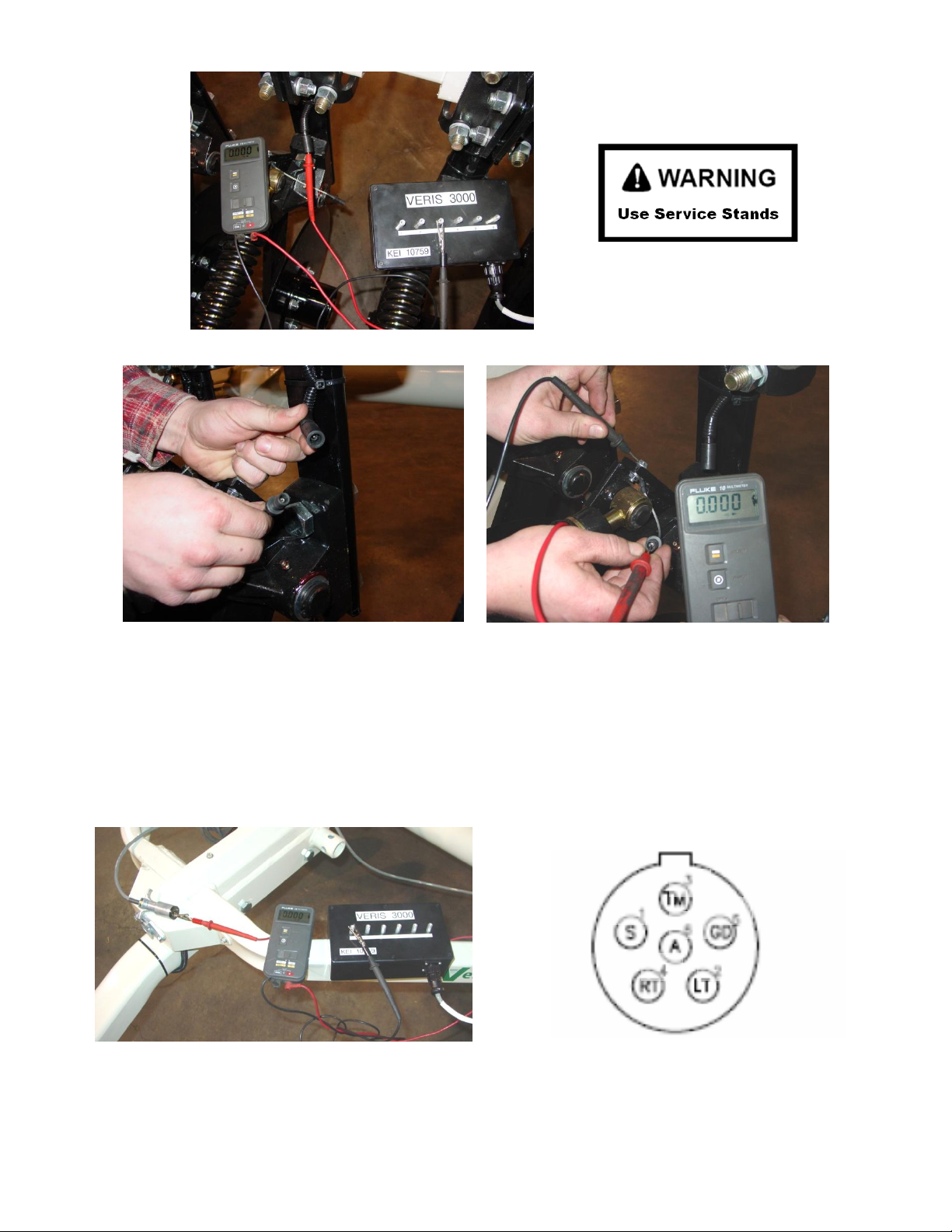
Pub. #OM17-MSP3
Figure 4.3 Testing cable at end of signal cable wiring harness
Figures 4.4 ab. a. Separating sure-seal connector b. Testing terminal connector wire
4. If there is a >2 ohm reading in the signal cable harness or signal extension cable, visually
inspect the wiring harness and cable extension for damage. If a visual inspection doesn’t
reveal a problem, you will need to test continuity of the wiring harness and cable. You will
need to ohm these cables out individually. Disconnect signal extension cable from
implement and insert ohmmeter leads into sockets as shown below.
Figures 4.5 a and b. Checking continuity of signal extension cable with one ohmmeter lead
contacting pins in extension cable end, and other lead contacting corresponding test box terminal.
6-8
Page 83

Pub. #OM17-MSP3
5. To ohm out the wiring harness, disconnect the serial cable extension from the implement
and check continuity through the harness as shown in Figures 10a and 10b. While doing so,
check the pins and the sockets of the 6-pin connector for corrosion and fit. If necessary
spread the pins with a small screwdriver to tighten fit in sockets.
Figures 4.6 a and b. Checking continuity of signal harness, with one ohmmeter lead contacting
pins in connector and other lead contacting corresponding coulter-electrode.
Note: intermittent electrical problems are difficult to diagnose. Flex wiring and connectors while
checking continuity.
B. Testing Coulter-Electrode continuity
1. Place ohmmeter lead on terminal wire bolt and other lead on disk blade. Rotate blade ¼
turn. If readings are consistently above 2 ohms, check for excessive corrosion at the coulter
blade mounting bolts, or the terminal located near the coulter pivot. Make sure that high
ohm readings are not due to poor contact between blade and ohmmeter lead. Re-test
holding lead firmly against edge of blade, removing rust or paint if necessary.
2. If ohms jump over 2 ohms when the blade is rotated, and you were careful to maintain good
contact between the lead and the blade, the problem is likely inside the hub. Because
electrical signals cannot be sent consistently through the coulter bearing, Veris has
designed a more reliable path for the EC signal to travel. A special hub with a spring plunger
presses against the spindle of the coulter, serving as a commutator. Shown below is a cutaway view of the hubcap and plunger assembly. When ohm readings jump during blade
rotation, it is due to the greased rollers on the bearing making intermittent and inconsistent
contact. See Maintenance and Service procedure #4: Spring Plunger adjustment and
replacement on adjusting and replacing spring plungers.
6-9
Page 84

Pub. #OM17-MSP3
hubcap
commutator
coulter
spindle
Figure 4.7
C. Testing Coulter-Electrode isolation
If continuity tests show no excessive resistance on any channel, yet erratic soil EC readings
continue, or if EC readings do not drop to –1 when unit is out of the soil, it is possible that the
channels are not isolated. This could be the result of a pinched wiring cable, causing channels to
short out. Or, one of the coulter-electrodes is no longer insulated properly from the frame or
adjacent coulter-electrodes.
1. If EC readings do not drop to –1 when unit is raised, disconnect signal cable extension from
implement. If readings don’t drop to –1, the problem is with the signal cable extension. If
readings show -1, re-insert the signal cable extension into the implement. Disconnect the
sure-seal terminal connector wire from each coulter electrode. If readings don’t drop to –1,
the problem is with the wiring harness. If this is the case, you should replace the wiring
harness. If readings do drop, re-insert the signal cable extension into the implement. The
problem is with one or more of the coulter-electrodes. Proceed as follows:
sure-seal pin
sure seal socket
Figure 4.8
6-10
Page 85

Pub. #OM17-MSP3
no
continuity
grounded
bolt
coulter
terminal
2. Inspect nylon insulation slides under coulterelectrode mounting brackets. These nylon insulators
may become worn or brittle, or may slip out from
under mounting bracket. Repair and replace as
necessary. Make sure that all electrode coulter Ubolts are properly tightened to clamp mounting
bracket and insulation tightly to frame.
Figure 4.9
3. Disconnect signal cable from instrument or front of frame. Check so see that no metal part
of the any coulter electrode is in contact with the implement frame. This may be by visual
inspection or by connecting one lead of an ohmmeter to the individual coulter electrode, and
the other to a grounded fastener on the frame. If the coulter electrode is properly isolated,
no reading will be obtained. Make sure that all electrode coulter clamp bolts are properly
tightened to prevent lateral movement of the coulter electrode.
Figures 4.10 a and b
4. Wet soil on the toolbar could be a pathway for the EC signal to short. Test coulter-to-coulter
and coulter-to-frame isolation by checking resistance between coulter-electrodes. Any
continuity from one coulter to another is not acceptable. Remove buildup of wet soil,
especially if is bridges across insulation slides. It may be necessary to remove coulter
mounting brackets and clean toolbar, if problem persists.
Figure 4.11 Wet soil buildup on toolbar may cause EC
signal to short.
6-11
Page 86

Pub. #OM17-MSP3
Procedure #5 Spring Plunger adjustment and replacement
The spring plungers are located in the center of each coulter electrode hub cap, and are vital to
maintain good continuity through the coulter hub bearings. They are factory preset, and should
not need routine adjustment. If a continuity test shows abnormally high resistance, the plungers
should be checked. This may be performed in the following manner:
1) Check coulter hub bearing preload by grasping coulter blade and pushing
from side to side. If there is any noticeable movement, bearing preload is
incorrect, or bearings are failing --and this can damage the spring plunger ;
see procedure #8 for adjustment or replacement.
2) Remove the 3/8” allen head set screw.
3) Remove the plunger by turning counter-clockwise.
4) Depress the spring loaded tip on a hard surface to determine if
plunger has adequate tension and can move freely.
5) If the plunger will not move freely, replace. Coat the threads with di-electric
silicone grease before installation.
6) If the plunger appears to be in good working order, reinstall in the hub, and
adjust until it bottoms against the spindle end. Rotate 1/2 turn backward to
allow adequate clearance. Improper adjustment will result in premature
failure (too little tolerance) or poor continuity (too much tolerance). See
Figure 5.1 below to view proper clearance.
7) Reinstall locking set screw and tighten firmly on top of plunger. The top of
the setscrew should be even with the face of the hub. If not, remove and
adjust the plunger inward or outward as necessary.
8) Re-test coulter electrode continuity
Figure 5.1
In some cases, you may have to remove the hub cap to service the spring plunger, if the
plunger is rusted in the cap, or if the readings are still unsatisfactory with the new plunger
installed.
6-12
Page 87

Pub. #OM17-MSP3
Procedure:
1) Remove hub cap by turning clockwise with a pipe wrench or large
adjustable wrench – these caps have left hand thread to prevent loosening
during field rotation.
2) If plunger is frozen in cap, remove allen head set screw on top of plunger
and apply penetrating oil on both sides of plunger. Let this stand for a few
minutes and try to remove. If it will not back out with allen wrench, lock
vise grips on the inside portion and turn out through inside of hub.
3) Clean all hub cap surfaces, install new o-ring, coat plunger and set screw
with di-electric grease and install as outlined above.
4) At the same time, inspect the end of the spindle. Over time the plunger will
wear a slight depression in the spindle face. This is common, and more
noticeable on high acreage units, or units that have been operated at high
field speeds. If the depression is 1/6” or more, carefully grind the face of
the spindle. Cover the bearing with a cloth or towel to prevent grinding dust
from entering the hub and bearings..
5) Re-install hub cap and tighten firmly. You may have to re-set the plunger
to compensate for the reduced length on the newly ground spindle. Readjust as outlined above.
Note: If you are still unable to obtain favorable resistance readings, check for excessive corrosion
at the coulter blade mounting bolts, or the terminal located near the coulter pivot. It may be
necessary to grind the spindle end smooth, if a dimple has developed.
6-13
Page 88

Pub. #OM17-MSP3
Procedure #6: Diagnosing GPS-related problems
If you do not see a GPS, DGPS, or RTK in the upper left-hand corner of the EC Surveyor screen,
you do not have GPS coming in, and no data will be sent out the serial port for logging.
Figure 6.1
Insure your GPS receiver is powered and outputting only two NMEA strings GGA, and either
VTG or RMC at a 1hz rate; 4800 baud, 8 data bits, no parity, 1 stop bit. Verify that your GPS cable
is sending GPS data through pin 2, pin 5 is ground, and no other pins have signal or power on
them. The most common issue is hz rate. If the GPS has been used for lightbar guidance it may
have been set to a 5 or 10 hz rate. It will need to be changed to 1 hz in order for the
OpticMapper/EC controller to accept it.
Shown below is a Troubleshooting tree for diagnosing GPS signal problems. It is not meant to
replace your GPS receiver user manual—it merely shows how to determine if your receiver is
sending the GPS signal that the EC Surveyor needs.
Figure 6.2
6-14
Page 89

Pub. #OM17-MSP3
If it becomes necessary to send GPS data into your PC, you will use a program called
HyperTerminal. This program is in all Windows software. It is designed to record serial data
streaming into a serial or USB port on the computer. The purpose of this is two-fold: 1) it verifies
whether your GPS and cables are delivering the proper messages, and 2) it give Veris
Technologies support personnel a GPS data file to test.
Here’s how to use HyperTerminal
1. Plug the GPS output cable into the laptop serial input (or USB-serial hub); no null modem is
needed
2. Verify in Device Manager which Com port the GPS is connected to (Start--Settings—Control
Panel—System—Hardware—Device Manager—Ports
3. Start the “HyperTerminal” program under “Accessories” in Windows.
Figure 6.3
4. Give your HyperTerminal session a name such as gps trial when the program prompts you
for the name of your connection and then hit “OK”.
Figure 6.4
6-15
Page 90

Pub. #OM17-MSP3
5. The program will then ask you for a phone number. Instead of entering a phone number,
specify the proper serial port number. For example, if Com 1 of the laptop is being used,
specify “Direct to Com 1” under “connect using:” at the bottom of the entry area.
Figure 6.5
6. HyperTerminal will then display a configuration menu where you can specify 4800 bits per
second, 8 data bits, no parity, 1 stop bit and no flow control.
Figure 6.6
6-16
Page 91

Pub. #OM17-MSP3
7. At this point, upon clicking ok, legible strings of GPS data should begin appearing on the
laptop screen. Here’s an example of a typical set of strings:
$GPGGA,191528.00,3851.0333,N,09737.2342,W,2,08,1.3,372.7,M,27.3,M,10.0,0100*69
$GPRMC,191528.00,A,3851.0333,N,09737.2342,W,0.1,0.0,090998,6.3,E*48
8. If GPS data doesn’t appear, recheck the port and configuration settings to make sure they
are correct. If the data won’t appear correctly in HyperTerminal, consult your GPS supplier
to see what adjustments (connectors or software) are necessary to bring the signal into a
computer.
9. If the signal appears correctly on HyperTerminal and it shows that the required strings are
being output, highlight a page of strings, copy and paste into Word or Wordpad before
exiting HyperTerminal.
10. Retry the unit with the Veris instrument. If it still doesn’t work, please email the page of GPS
strings from HyperTerminal to Support@veristech.com, along with your contact information.
6-17
Page 92

Pub. #OM17-MSP3
Procedure #7: SD card formatting and firmware updates
USING A VERIS SD CARD IN OTHER DEVICES CAN CAUSE FILE CORRUPTION.
Insert a standard SD card (not SDHC type) into a SD card reader which connected to your
computer.
Open “My Computer” folder. Right click on the SD card icon, and select the “Format”.
Figures 7.1 a and b.
In the format window, click on the file system tab and select “FAT” not “FAT32”.
Then press “Start”.
When complete, remove the card.
6-18
Page 93

Pub. #OM17-MSP3
Updating Data Logger Firmware
1. Shut off the power of the Data Logger.
2. Copy the firmware on the SD card. (firmware found at veristech.com software download site)
3. Put the SD card into the Data Logger.
4. Turn on the power of the Data Logger.
5. Press the RESET button on the rear panel and (1) key simultaneously.
Figure 7.2
6. Hold the (1) key and release the RESET button.
7. If you can see the following messages, then release the (1) key.
Figure 7.3
8. If you want to update new software, press (2) key.
6-19
Page 94

Pub. #OM17-MSP3
9. Then you can see the following messages in sequence.
Figures 7.4 a and b.
10. Do not shut off the power, but repeat from step 5 to 9 again.
11. Press the RESET button or shut off and turn back on the power.
12. Check the LCD display. If nothing shows up in the LCD, or if display doesn’t contain the new
firmware version number, please repeat from step 1 to 11.
6-20
Page 95

Pub. #OM17-MSP3
Seal
Hub
Nut
Thrust Washer
Bearing
Swing arm
Procedure #8: Bearing Repair and Replacement
The coulter electrode hubs operate in a significantly harsh environment, and annual inspection is
of utmost importance. The double-lip seals are designed to keep grease in, and contaminates out,
but they are the cause of practically all hub failures. It is advisable to disassemble, clean and
repair annually. To perform this maintenance, do the following:
1) Remove hub cap by turning in a clockwise direction (left-hand thread
prevents loosening in operation).
2) Remove cotter pin, castle nut, thrust washer, and remove hub.
3) Remove outer bearing and knock out inner bearing and both races (cups)
4) Veris recommends that you purchase our Coulter Hub Repair Kit (PN
32641) that includes new bearings, races, seal, o-ring and cotter pin.
5) Thoroughly wash hub in solvent and dry.
6) Spindle end may need grinding—see spring plunger replacement
Procedure #4
7) Reassemble and adjust bearing pre-load by fully tightening spindle nut,
then backing off until you can turn the hub fairly easily with one hand–
normally this involves backing off 1- 2 slots on the castle nut, and
inserting cotter pin. Excessive pre-load may cause plugging in extremely
loose soil conditions, and excessive endplay may damage the spring
plunger. Hub should have no side play when assembled, but should turn
with little resistance. Drive round end of cotter pin firmly into nut, and bend
upper portion of cotter pin upward and trim of excess length of both top and
bottom with cutting pliers. Do not bend cotter pin over the end of
spindle as it will interfere with spring plunger.
8) Fill hub via grease zerk until grease pushes through outer bearing.
9) Install hub cap by threading counter-clockwise on the hub. Check to make
sure that hub still rotates freely. If not, the cotter pin may too long, and is
contacting hubcap –remove cap and check cotter pin length.
10) Adjust spring plunger clearance as mentioned in Procedure #5.
Figure 8.1
6-21
Page 96

Pub. #OM17-MSP3
Procedure #9 SoilViewer Troubleshooting
OpticMapper or pH controller is not found
Check to ensure the com which the EC Surveyor/OpticMapper is connected to is present under the
device manager. To get to the device manager go to StartSettingsControl PanelSystem
Click on the Hardware tab and then click on the device manager button. Click on the “+” sign next
to Ports and make sure the port is listed here. In this case a USB to serial converter is being used
and the port is listed as USB Serial Port (COM33)
Figure 9.1
If the port is not listed here, then unplug and replug the USB – Serial converter cable and ensure
the power is on to the EC surveyor. If USB – Serial port is still unavailable then reinstall the drivers
following the manufactures instructions for driver installation.
6-22
Page 97
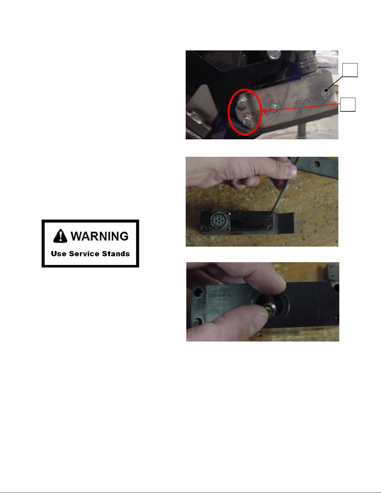
Procedure #10: Optical Wear plate and Side Wear plate replacement
1
2
Figure 10.1
Figure 10.2
Figure 10.3
1. Remove the bolts attaching the optical
sensor assembly to the row unit.
2. Remove the hex screws attaching the side
plates to the optical sensor.
3. To remove wear plate, unscrew the hex
bolts on the top of the optical sensor as
shown in figure 10.2
4. Now to replace the wear place, ensure the
O-ring is seated in the o-ring grove as shown
in figure 10.3.
5. Install the wear plate and side plates,
Then mount the assembly back to the row
unit.
Pub. #OM17-MSP3
6-23
Page 98

Procedure #11 pH Module
Figure 11.3
1. Unit doesn’t cycle when “1” key is pressed (in Automatic Mode)
-check to be sure you are in Data Acquisition mode—screen below:
Figure 11.1
-check to be sure that external controller is in Automatic mode. If it isn’t, this screen will
appear:
Figure 11.2
-follow troubleshooting flow chart below and see related Procedures in Maintenance and
Procedure Section
Pub. #OM17-MSP3
6-24
Page 99

Pub. #OM17-MSP3
Figure 11.4
2. Functions Aren’t Working in Manual Mode
-follow troubleshooting flow chart below and see related procedures in Maintenance and
Service Procedure Section.
1. Sampling mechanism locks up or mis-cycles
-press “1” to disengage, turn external controller to Manual and check prox sensor adjustment
(see Procedure #4 in Maintenance and Service Procedure Section.)
-check DGPS signal
-if status of sampler shows “Cycling” for long periods, set sampler shank to shallower position.
In hard soil, sampler shoe may not be able to penetrate to the depth needed to move plate off
prox sensor. (see Procedure #4 in Maintenance and Service Procedure Section.))
6-25
Page 100

Pub. #OM17-MSP3
Use pH simulator to test external controller and Veris
instrument.
On/Off key (Turn pH simulator OFF when test is completed)
Attach to each BNC port to test each circuit
Press Select button to toggle from 4 to 7 to 10. Light above pH
value will light. View Veris display to confirm these readings
at each simulator setting:
4 should read -2, 7 should read .6, and 10 should read 3.9.
(Note: the simulator is designed for glass electrodes; for
antimony the readings are those listed above)
2. Wash system malfunctioning: no water being pumped
-are there at least 10 gallons of water in tank?
-are pumps running? If not, check electrical connections and 12 volt power to them
-check pressure switch on pump—wiggle wire, disconnect and reconnect; direct wire if needed
-is filter plugged?
-is ball valve open?
-disconnect quick couplers to help pumps prime
3. pH readings seem erroneous or won’t calibrate
-Use pH simulator to test External Controller and Veris instrument. Re-test with pH simulator
set to High Impedance
Figure 11.5
-check for moisture around BNC connectors and for proper installation and fit of the BNC cover
over BNC connections (if the pH simulator readings are not close to the default settings, blow
compressed air into BNC ports on external control module)
4. Sampling shoe plugging
-verify if shoe is plugged: wash electrodes to create a wet sample in the shoe; in manual mode
lower sampler to full depth and drive forward; if soil in the sampling trough is now dry, fresh soil
has entered and the shoe isn’t plugged
-to clean plugged shoe, raise implement, lower shoe manually to maximum depth, and drive
forward at high rate of speed as you lower the implement completely; if it doesn’t clear, clean
manually (put transport locks in before working under unit)
-clean cutting shoe thoroughly, especially if it has dried mud in it
-check cutting shoe and scraper for wear; replace as needed
-check scraper adjustment by manually raising and lowering sampler assembly. Does scraper
completely clean the cutting shoe face? See Field Operation section for proper adjustment
-adjust row cleaner to clear residue more completely
-adjust firming wheel down to firm soil
-lower sampling depth to engage soil with better coring properties
5. pH readings are repeatedly >.5 different or are slow to settle,
-check shoe for sample quality. If only a small amount of soil is present, reduce field speed to
retain adequate core. If crop residue is present, adjust cleaning disks to reduce crop residue in
sampling area.
6-26
 Loading...