

Page 1

LDRA6 USER GUIDE
RLE TECHNOLOGIES
Page 2

©2008 RLE Technologies 110046 Rev 1.6 (08/2008)
Page 3
SEAHAWK LDRA6
Page 4

PRODUCT REGISTRATION
Product registration helps RLE Technologies inform owners of:
• Product Upgrades
• Firmware Enhancements
• New products and Technologies
• Special Offers Available Only to Registered Users
Submit registration information on the Support/Product Registration webpage at www.rletech.com
**Any information provided to RLE Technologies through the registration form will be regarded as confidential.
To read our Privacy Policy, please visit our website: rletech.com
TECHNICAL SUPPORT
Personal assistance is available Monday through Friday, from 8:00 a.m. to 5:00 p.m. MST.
For more information, please visit the Documentation/Files section on the
LDRA6 webpage of our website at www.rletech.com
A request for assistance may be sent to support@rletech.com
Otherwise, please call us directly at: (970) 484-6510 - press “2” for technical support
The following information is located on the bottom of each LDRA6 unit.
Please have this information available whenever a technical support call is placed:
Product Model Number _____________________________________________________
Product Serial Number _____________________________________________________
Product Manufacture Date ___________________________________________________
.
.
.
©2008 RLE Technologies 110046 Rev 1.6 (08/2008)
Page 5

User Guide: LDRA6 Table of Contents
TABLE OF CONTENTS
Chapter 1: Product Overview ........................................................................................................................................2
1-1 Description......................................................................................................................................................2
1-2 LDRA6 Front Panel Indicators .......................................................................................................................2
1-2.1 Zone LEDs ...........................................................................................................................................2
1-2.2 Power LED...........................................................................................................................................2
1-2.3 Audible Alarm......................................................................................................................................2
1-2.4 Quiet/Test/Reset Switch.......................................................................................................................2
Chapter 2: Connections & Settings ...............................................................................................................................4
2-1 LDRA6 Board .................................................................................................................................................4
2-1.1 TB1 – Power ........................................................................................................................................5
2-1.2 POW1 – Power.....................................................................................................................................5
2-1.3 TB2, TB3 – Zone Inputs.......................................................................................................................5
2-1.4 TB5, TB4 – Zone Alarm Relays...........................................................................................................5
2-1.5 TB6 - Summary Relay..........................................................................................................................6
2-1.6 TB7 – RS485 Connection.....................................................................................................................6
2-2 SW1 - Relays and Alarm.................................................................................................................................7
2-2.1 SW1, Position 1: Summary Relay Supervised / Unsupervised ............................................................7
2-2.2 SW1, Position 2: Relays Latched / Unlatched......................................................................................7
2-2.3 SW1, Position 3: Zone Relay Linkage .................................................................................................7
2-2.4 SW1, Position 4: Zone Relays Supervised / Unsupervised .................................................................. 7
2-2.5 SW1, Positions 5: Leak Alarm Delay...................................................................................................7
2-2.6 SW1, Positions 6: Summary Relay Silence-Ability .............................................................................7
2-2.7 SW1, Positions 7 and 8: Re-alarm Time ..............................................................................................8
2-3 SW2 – Modbus Addressing.............................................................................................................................8
2-4 SW4 through Sw9 ...........................................................................................................................................8
2-5 R1 – Leak Detection Cable Sensitivity Setting ...............................................................................................8
Chapter 3: Installation ...................................................................................................................................................9
3-1 Before You Begin ...........................................................................................................................................9
3-2 Connecting the Water Leak Detection Cable ..................................................................................................9
3-2.1 Secure the Cable to the Floor ...............................................................................................................9
3-2.2 Recommended Cable Installation.......................................................................................................10
3-3 Apply Power to the Unit ...............................................................................................................................11
3-3.1 Power via Wall Adapter .....................................................................................................................11
3-3.2 Power via Direct Line.........................................................................................................................11
Chapter 4: Start-Up......................................................................................................................................................12
4-1 Boot-Up.........................................................................................................................................................12
4-2 Displaying the Help Menu ............................................................................................................................12
4-3 Function Commands .....................................................................................................................................13
4-3.1 c – Contact Closure Settings ..............................................................................................................13
4-3.2 ld – Leak Delay Setting......................................................................................................................13
4-3.3 sens – Leak Zone Sensitivity.............................................................................................................. 13
4-3.4 e – View Eeprom Data .......................................................................................................................14
4-3.5 er – Erase Eeprom Data – Restores Factory Defaults.........................................................................14
4-3.6 mbb – View / Change Modbus Baud Rate ......................................................................................... 14
4-3.7 mbp – View / Change Modbus Parity ................................................................................................14
4-3.8 mr – Reset Modbus Port and Statistics...............................................................................................14
4-3.9 m – View Modbus Port Settings and Statistics...................................................................................14
4-3.10 t – Toggle Modbus Trace On/Off.......................................................................................................15
4-3.11 z – Display Leak Zone Readings........................................................................................................15
4-3.12 sr – summary relay mode ...................................................................................................................15
4-3.13 zr – zone relay mode ..........................................................................................................................15
4-3.14 x – Exit to Bootloader ........................................................................................................................15
www.rletech.com 970 484-6510 i
Page 6

Table of Contents User Guide: LDRA6
Appendix A: Modbus Communications ..................................................................................................................... 16
A-1 Modbus Implementation of the LDRA6....................................................................................................... 16
A-1.1 Modes of Transmission ..................................................................................................................... 16
A-1.1.1 Slave Address Field ................................................................................................................ 16
A-1.1.2 Function Field ......................................................................................................................... 16
A-1.1.3 Data Field................................................................................................................................ 16
A-1.1.4 Error Check Field.................................................................................................................... 16
A-2 Packet Communications for the LDRA6...................................................................................................... 17
A-2.1 Read Output Registers....................................................................................................................... 17
A-2.2 Read Input Registers.......................................................................................................................... 18
A-2.3 Present Single Register...................................................................................................................... 19
A-2.4 Present Multiple Registers................................................................................................................. 19
A-3 RTU Framing ............................................................................................................................................... 20
A-4 Modbus Mirroring ........................................................................................................................................ 21
Appendix B: Troubleshooting .................................................................................................................................... 22
Appendix C: Technical Specifications........................................................................................................................ 23
ii 970 484-6510 www.rletech.com ii
Page 7

User Guide: LDRA6 List of Figures and Tables
LIST OF FIGURES AND TABLES
Figure 1-1: LDRA6 Front Panel Indicators ..................................................................................................................3
Figure 2-1: LDRA6 Board............................................................................................................................................4
Figure 3-1: Water Leak Detection Cable......................................................................................................................9
Figure 3-2: Cable Installation Methods ...................................................................................................................... 10
Table 1: Read Output Registers Packet Structure.......................................................................................................17
Table 2: Output Registers...........................................................................................................................................17
Table 3: Read Input Registers Packet Structure .........................................................................................................18
Table 4: Input Registers..............................................................................................................................................18
Table 5: Status Flags (Register 30001).......................................................................................................................18
Table 6: Status Flags (Register 30008).......................................................................................................................19
Table 7: Present Single Register Packet Structure......................................................................................................19
Table 8: Present Multiple Registers Packet Structure .................................................................................................19
Table 9: Modbus Slave Address................................................................................................................................. 20
Table 10: Query Sample.............................................................................................................................................20
Table 11: Response Sample........................................................................................................................................20
www.rletech.com 970 484-6510 iii
Page 8
Chapter 1: Product Overview User Guide: LDRA6
CHAPTER 1: PRODUCT OVERVIEW
1-1 DESCRIPTION
The LDRA6 is a complete monitoring system that detects and reports the presence of water and other
conductive liquids, as well as monitors dry contact alarm points. The LDRA6 couples SeaHawk Water
Leak Detection Cable (SC) with an advanced control head to monitor six individual zones. When a
conductive liquid comes in contact with the SC cable, an alarm sounds and the summary alarm relay and
zone relay activate. The LED that corresponds with the appropriate zone also illuminates and an audible
alarm is activated. Each LDRA6 input can also be configured to detect a dry contact’s change of state (NO
or NC) and annunciate the alarm on the front panel.
The LDRA6 is a supervised system - it continuously monitors the cable for leaks and cable integrity. A
cable break causes a cable fault indication. An alarm sounds and the appropriate zone relay and the
summary alarm relay activate. The appropriate LED changes to indicate a cable fault has occurred.
The dry contact relays in the LDRA6 may be configured as supervised or unsupervised (see section 2-2 for
configuration options). Each zone can be configured with unique, individual settings. When the user
specified alarm condition occurs, the LDRA6 activates the appropriate relay and alarm LED.
NOTE
The LDRA6 produces an alarm in the following conditions:
:
Leak Detected
Cable Fault
Dry Contact Alarm Condition (User Specified)
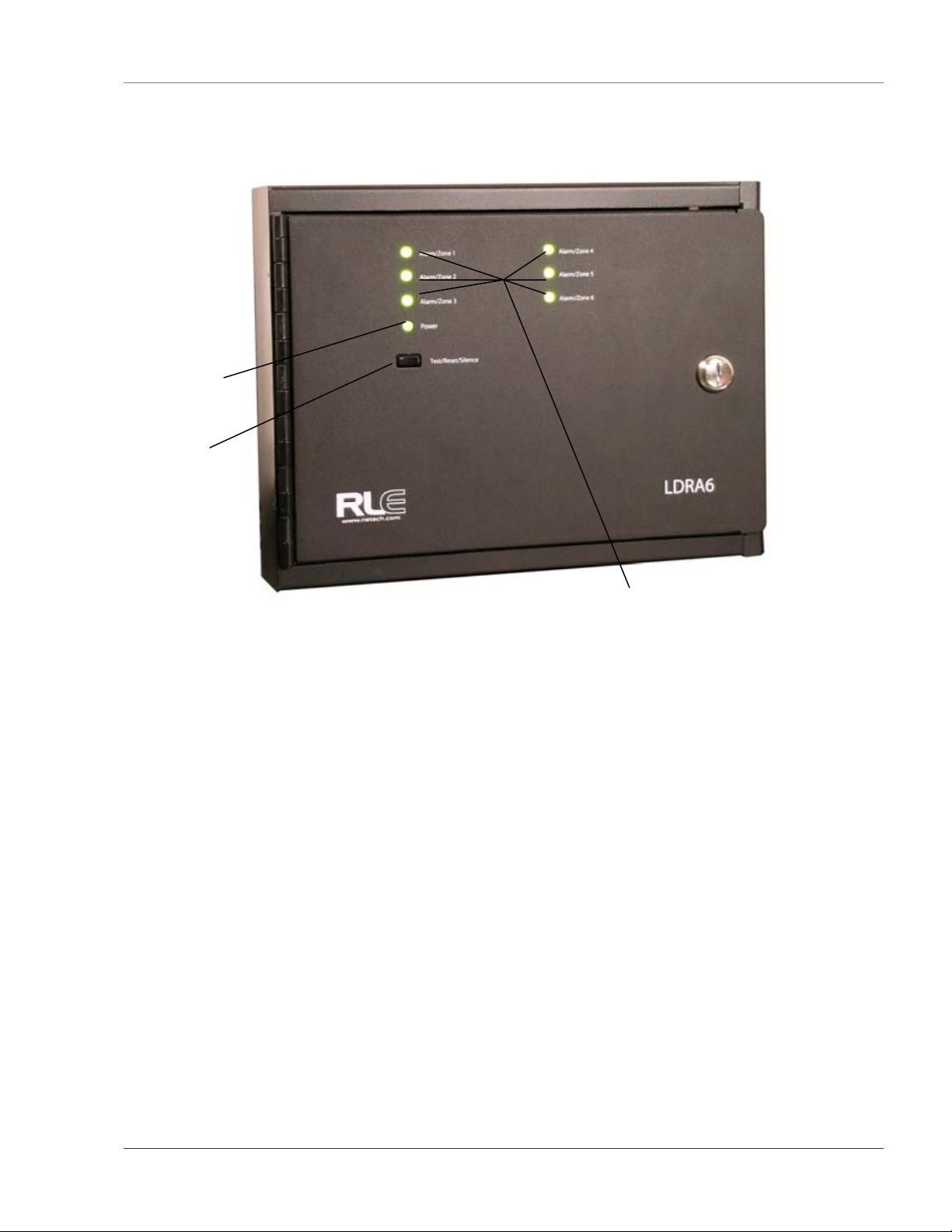
1-2 LDRA6 FRONT PANEL INDICATORS
1-2.1 Zone LEDs
One tri-color LED for each zone.
Default Leak Detection Cable Setting:
On solid and green for normal cable conditions.
Flashes quickly and turns red if a leak is detected in the zone.
Flashes quickly and turns yellow if a cable fault is detected in the zone.
On solid once an alarm is silenced.
Default Dry Contact Setting:
On solid and green for normal, non-alarm conditions.
Flashes quickly and turns red (by default) if an alarm condition is detected in the zone.
On solid once an alarm is silenced.
1-2.2 Power LED
On (green) as long as power is on.
1-2.3 Audible Alarm
Activates when an alarm condition is detected. Silenced with the Quiet/Test/Reset switch.
1-2.4 Quiet/Test/Reset Switch
During alarm, the audible alarm is silenced, and any LED(s) in alarm will glow solidly. If the alarm goes
away, the LED(s) will flash slowly. Hold down the Quiet/Test/Reset switch to reset all alarms and
complete and self test cycle. If any alarms still exist, the unit will not reset the corresponding zones.
www.rletech.com 970 484-6510 2
Page 9
User Guide: LDRA6 Chapter 1: Product Overview
Power LED
Test / Reset/ Silence Switch
Leak /Cable Detected LEDs
Figure 1-1: LDRA6 Front Panel Indicators
3 970 484-6510 www.rletech.com
Page 10

Chapter 2: Product Overview User Guide: LDRA6
CHAPTER 2: CONNECTIONS & SETTINGS
2-1 LDRA6 BOARD
The LDRA6’s zone connectors, labeled TB2, are found at the bottom of the board on the double-stacked
terminal block. The switches on the board are labeled SW1 and SW2. The unit has one dial, labeled R1,
which is used to manually adjust the sensitivity for all zones. Sensitivity for individual zones may be
configured through the LDRA6’s RS232 Craft Port configuration, labeled P2. The switches for
configuring Dry Contact or Leak Detection monitoring for zones are labeled SW4 through SW9.
P2
RS232
R1
Leak Sensitivit
SW4 – SW9
y
Zone
Configuration
TB7
RS485
TB6
Summary
Relay
TB5
Zone
Alarm
Relays
TB4
Zone
Alarm
Relays
Zone
Figure 2-1: LDRA6 Board
TB3
TB2
Zone
POW1
Power
TB1
Power
www.rletech.com 970 484-6510 4
Page 11

User Guide: LDRA6 Chapter 2: Connections & Settings
2-1.1 TB1 – Power
The LDRA6 connects to a 24VDC power supply using TB1, a two position connector labeled 24VDC.
2-1.2 POW1 – Power
Power can also be supplied to the unit through POW1. This is a wall adapter plug connection. This also
requires 24VDC.
2-1.3 TB2, TB3 – Zone Inputs
SeaHawk Leak Detection Cable (SC) and/or dry contact wires connect to the LDRA6 through TB2. Fifteen
foot (4.57m) leader cables (one is included in each leader cable kit, part #LC-KIT) are required for leak
detection cable connections only. Dry contact wires must be user supplied or may be supplied with your
dry contact device. Connect cables/wires as follows:
Position Leak Detection Cable Dry Contact Wire
TB3-1 Zone 1 White Zone 1 Input-1
TB3-2 Zone 1 Black Zone 1 Input-2
TB3-3 Zone 1 Green N/A
TB3-4 Zone 1 Red N/A
TB3-5 Zone 2 White Zone 2 Input-1
TB3-6 Zone 2 Black Zone 2 Input-2
TB3-7 Zone 2 Green N/A
TB3-8 Zone 2 Red N/A
TB3-9 Zone 3 White Zone 3 Input-1
TB3-10 Zone 3 Black Zone 3 Input-2
TB3-11 Zone 3 Green N/A
TB3-12 Zone 3 Red N/A
TB2-1 Zone 4 White Zone 4 Input-1
TB2-2 Zone 4 Black Zone 4 Input-2
TB2-3 Zone 4 Green N/A
TB2-4 Zone 4 Red N/A
TB2-5 Zone 5 White Zone 5 Input-1
TB2-6 Zone 5 Black Zone 5 Input-2
TB2-7 Zone 5 Green N/A
TB2-8 Zone 5 Red N/A
TB2-9 Zone 6 White Zone 6 Input-1
TB2-10 Zone 6 Black Zone 6 Input-2
TB2-11 Zone 6 Green N/A
TB2-12 Zone 6 Red N/A
2-1.4 TB5, TB4 – Zone Alarm Relays
These are the Zone Alarm Relay output terminal blocks (Form C). A status LED is located above each
relay, which will indicate the state of the relay (on/off). These relays can be configured as supervised or
unsupervised, latched or unlatched (unsupervised and unlatched by factory default). Connect the Zone
Alarm Relay wires to TB3 and TB4 as follows:
TB5-1 Zone 1 alarm relay normally open (NO)
TB5-2 Zone 1 alarm relay common (C)
TB5-3 Zone 1 alarm relay normally closed (NC)
TB5-4 Zone 2 alarm relay normally open (NO)
TB5-5 Zone 2 alarm relay common (C)
TB5-6 Zone 2 alarm relay normally closed (NC)
5 970 484-6510 www.rletech.com
Page 12

Chapter 2: Product Overview User Guide: LDRA6
TB5-7 Zone 3 alarm relay normally open (NO)
TB5-8 Zone 3 alarm relay common (C)
TB5-9 Zone 3 alarm relay normally closed (NC)
TB4-1 Zone 4 alarm relay normally open (NO)
TB4-2 Zone 4 alarm relay common (C)
TB4-3 Zone 4 alarm relay normally closed (NC)
TB4-4 Zone 5 alarm relay normally open (NO)
TB4-5 Zone 5 alarm relay common (C)
TB4-6 Zone 5 alarm relay normally closed (NC)
TB4-7 Zone 6 alarm relay normally open (NO)
TB4-8 Zone 6 alarm relay common (C)
TB4-9 Zone 6 alarm relay normally closed (NC)
2-1.5 TB6 - Summary Relay
This is the Summary Relay output terminal block (Form C). A status LED is located to the right of the
relay, which will indicate the state of the relay (on/off). This relay can be configured as supervised or
unsupervised, latched or unlatched. Connect the Summary Relay wires to TB5 as follows:
TB6-1 Summary alarm normally open (NO)
TB6-2 Summary alarm common (C)
TB6-3 Summary alarm normally closed (NC)
2-1.6 TB7 – RS485 Connection
The LDRA6 can communicate with other devices through the RS485 terminal block. Wire as follows:
TB7-1 + or A wire
TB7-2 – or B wire
TB7-3 Shield or GND wire
www.rletech.com 970 484-6510 6
Page 13

User Guide: LDRA6 Chapter 2: Connections & Settings
2-2 SW1 - RELAYS AND ALARM
2-2.1 SW1, Position 1: Summary Relay Supervised / Unsupervised
Configures the Summary Alarm relay as supervised or unsupervised. If a relay is supervised, the relay
picks until power goes off or until an alarm is detected. The alarm then releases to announce a change in
state. An unsupervised relay picks only when an alarm is detected.
1 = Supervised
0 = Unsupervised (factory default)
2-2.2 SW1, Position 2: Relays Latched / Unlatched
Configures all relays as latched or unlatched. If a relay is latched, the relay will remain in an alarm
condition until the Reset switch is pressed. If a relay is unlatched, the relay will remain in alarm until
either the Reset switch is pressed, or the condition that tripped the relay goes away.
1 = Latched
0 = Unlatched (factory default)
2-2.3 SW1, Position 3: Zone Relay Linkage
Configures all Zone Alarm Relays to link together and pick simultaneously upon alarm. When this switch
is turned on, if a zone goes into alarm, all six zone alarm relays and the summary alarm relay will pick.
When this switch is turned off, if a zone goes into alarm, only the zone alarm relay for the zone that is in
alarm and the summary alarm relay will pick.
1 = Individual Zone Alarm Relays Linked
0 = Individual Zone Alarm Relays Not Linked (factory default)
2-2.4 SW1, Position 4: Zone Relays Supervised / Unsupervised
Configures the individual Zone Alarm Relays as supervised or unsupervised. If a relay is supervised, the
relay picks until power goes off or until an alarm is detected. The alarm then releases to announce a change
in state. An unsupervised relay picks only when an alarm is detected.
1 = Supervised
0 = Unsupervised (factory default)
2-2.5 SW1, Positions 5: Leak Alarm Delay
Designates the unit’s leak delay time. Setting this switch to off uses the default leak alarm delay of 15
seconds. Setting this switch to on designate the leak alarm delay to use the value specified through the
unit’s craft port.
1 = Leak Alarm Delay set through Craft Port
0 = Leak Alarm Delay set at 15 seconds (factory default)
2-2.6 SW1, Positions 6: Summary Relay Silence-Ability
Configures the Summary Alarm Relay as silence-able or not silence-able. If the Summary Alarm Relay is
silence-able, the relay returns to normal when the Quiet/Test/Reset button is pressed. If the Summary
Alarm Relay is not silence-able, the relay stays picked until the alarm condition is cleared.
1 = Summary Alarm Relay is Silence-Able
0 = Summary Alarm Relay is Not Silence-Able (factory default)
7 970 484-6510 www.rletech.com
Page 14

Chapter 2: Product Overview User Guide: LDRA6
2-2.7 SW1, Positions 7 and 8: Re-alarm Time
Configures the unit’s re-alarm time. Set the switches as below for desired (approximate) re-alarm times:
1 1 = 24 hours
0 1 = 16 hours
1 0 = 8 hours
0 0 = Disabled; no re-alarming once silenced (factory default)
2-3 SW2 – MODBUS ADDRESSING
Configures the unit’s RS485 address. The unit’s address is set in bits and can range from 00000001 to
11111110 (1-254 in decimal notation).
00000000 = No Address (factory default)
00000001 = 1
00000010 = 2
00000011 = 3
…
11111101 = 253
11111110 = 254
2-4 SW4 THROUGH SW9
Configures each zone as a Leak Detection Cable input or a Dry Contact input. If configured as a Leak
Detection Cable input, the zone requires a 4-wire leak detection cable (SC) to monitor. If configured as a
Dry Contact input, the zone requires a 2-wire dry contact device to monitor. If any zone is not desired to be
used, set the zone to Dry Contact and normally open (factory default) to avoid unwanted alarms.
SW4 Up = Zone 1 is a Dry Contact input
SW4 Down = Zone 1 is a Leak Detection input
SW5 Up = Zone 2 is a Dry Contact input
SW5 Down = Zone 2 is a Leak Detection input
SW6 Up = Zone 3 is a Dry Contact input
SW6 Down = Zone 3 is a Leak Detection input
SW7 Up = Zone 4 is a Dry Contact input
SW7 Down = Zone 4 is a Leak Detection input
SW8 Up = Zone 5 is a Dry Contact input
SW8 Down = Zone 5 is a Leak Detection input
SW9 Up = Zone 6 is a Dry Contact input
SW9 Down = Zone 6 is a Leak Detection input
2-5 R1 – LEAK DETECTION CABLE SENSITIVITY SETTING
This potentiometer allows users to manually adjust the sensitivity setting for all six zones. Turn the dial
clockwise to make the zone less sensitive. This means a leak will be reported in that zone when a large
amount of water is present. Turn the dial counterclockwise to make the zone more sensitive. This means a
leak will be reported for the zone when a small amount of water is present.
This potentiometer can be overridden through the LDRA6’s craft port configuration for individual zones
(see section 4-3.3 for details).
www.rletech.com 970 484-6510 8
Page 15

User Guide: LDRA6 Chapter 3: Installation
CHAPTER 3: INSTALLATION
3-1 BEFORE YOU BEGIN
The LDRA6 is a wall mounted device. To secure the device to the wall, first open the door of the
enclosure. There are knockouts on the top and bottom of the enclosure. Remove as many as necessary.
Use drywall anchors and the holes in the back of the enclosure to secure the unit to the wall.
3-2 CONNECTING THE WATER LEAK DETECTION CABLE
A leader cable kit (part #LC-KIT) is required per zone to connect the LDRA6 to SeaHawk Leak Detection
Cable (SC). A leader cable is included in each LC-KIT; one end of this leader cable connects into the
LDRA6. This end of the cable is finished with stripped, bare wires. The other end features a mating
connector which connects with the SC cable. The end of the cable zone requires a removable end
terminator (EOL) which is also included in a leader cable kit (LC-KIT).
NOTE
A Leader Cable Kit (part #LC-KIT) is required per zone to connect the LDRA6 to
SeaHawk Leak Detection Cable (SC). Each LC-KIT includes a 15 foot (4.57m) leader
cable and an EOL terminator. The kits are NOT included with the LDRA6, and can
be purchased separately.
To connect the leader cable to the LDRA6, connect the wires (4) to the appropriate zone position of the
terminal block connectors (see section 2-1.3 for more wiring details). Adjust the appropriate zone
configuration for Leak Detection input (see section 2-4 for more details).
Once the leader cable is plugged into the terminal block, it is ready to be connected to the SC cable. To do
this, unscrew the EOL terminator from the end of the leader cable. Attach the first length of SC cable to
the leader cable. Route the SC cable according to the cable layout diagram, if provided. Lay the cable
according to figure 3-1 and section 3-2.1. Secure the EOL terminator on the unoccupied end of the SC
cable.
:
Figure 3-1: Water Leak Detection Cable
3-2.1 Secure the Cable to the Floor
Secure the cable to the floor with either J-clips (part #JC) or one of the other approved methods shown in
Figure 3-2. J-clips are the manufacturer’s recommended installation method.
Place one J-clip every three feet along the length of the SC cable. Place one J-clip at each turn of
the cable.
9 970 484-6510 www.rletech.com
Page 16

Chapter 3: Product Overview User Guide: LDRA6
If the cable is installed over an obstruction, clip the cable on both sides, as close to the obstruction
as possible.
Do not install the cable directly in front of an air conditioner. Allow a minimum of 6 feet (1.83m)
between the unit and the cable. If the SC cable is too close to the air conditioning unit’s air stream,
the moisture from the humidifier may cause false leak readings. If the cable must be installed in
front of an air conditioning unit, place the J-clips 12 to 18 inches (.305m to .457m)apart.
NOTE
It is important to finish the end of the SeaHawk Leak Detection Cable (SC) with the
end-of-line terminator (EOL). If the EOL terminator is not present, a cable fault will
register. Note any variances between the cable layout diagram and the actual cable
installation. Wait approximately one minute. No alarm should be present.
:
3-2.2 Recommended Cable Installation
Figure 3-2: Cable Installation Methods
www.rletech.com 970 484-6510 10
Page 17

User Guide: LDRA6 Chapter 3: Installation
3-3 APPLY POWER TO THE UNIT
Once cable for all the desired leak detection zones has been connected to the unit, power may be applied.
The LDRA6 operates on 24VDC power supplied by a wall adapter or a direct line. A power supply should
be run to the location of the unit.
3-3.1 Power via Wall Adapter
The LDRA6 can be powered by a wall adapter. Before connecting the wall adapter to the LDRA6, unplug
the adapter from the wall. If the adapter has a connector on the end, feed the cord through one of the
knockouts in the enclosure and plug it directly into the 24VDC receptacle located at POW1. Plug the other
end of the adapter into the wall. The LDRA6 should power up immediately.
3-3.2 Power via Direct Line
If the adapter does not have a connector on the end, strip the end of the adapter line so the two wires inside
are exposed. Strip the end of each of the two wires and feed them into the enclosure. Insert the two wires
into the terminal block labeled TB1. The minus, or ground, wire is placed into the right opening in the
terminal block. The plus, or live, wire is placed into the left opening in the terminal block.
Once all the wires have been placed inside the terminal block, tighten the three screws across the bottom of
the terminal block until the wires are securely held in place. Plug the other end of the wall adapter into the
wall. The LDRA6 should power up immediately.
11 970 484-6510 www.rletech.com
Page 18

Chapter 4: Product Overview User Guide: LDRA6
CHAPTER 4: START-UP
4-1 BOOT-UP
Make sure the RS-232 port is connected to a PC or terminal with a straight through cable. When the
LDRA6 is powered up, the boot ROM and flash program code are verified. Output similar to the screen
displayed below should appear on the terminal or terminal emulation software.
LDZ/Rasp6 Bootloader – LDZ6BOOT V2.1
Firmware Prgm Id: LDZ6/RASP6 V2.1
checksum valid
LDZ/Rasp6 bootup
LDZ6/RASP6 V2.1
Reading EEprom.......................................
..... ok
Modbus Addr:0 9600,8,N,1
4-2 DISPLAYING THE HELP MENU
Once the system reaches this point, type? and press Enter to display the Help Menu. The Help Menu lists
the function commands for the LDRA6.
Help Menu – LDZ6/RASP6 V2.1
c - view/change CC settings
ld - view/change leak delay
sens – view/change leak zone sensitivity
e - view eeprom data
er - erase eeprom data – restores factory defaults
mbb - change modbus baud rate
mbp - change modbus parity
mr - reset modbus port/statistics
m - view modbus port settings/statistics
t - toggle modbus trace on/off
z - display leak zone readings
sr - summary relay mode
zr - zone relay mode
x - exit to bootloader
www.rletech.com 970 484-6510 12
Page 19

User Guide: LDRA6 Chapter 4: Start-Up
4-3 FUNCTION COMMANDS
4-3.1 c – Contact Closure Settings
c displays the current contact closure settings for each zone. To adjust a zone’s configuration, use the
following format: cX/type/offcolor/oncolor/delay
X is the zone number and can range from 1-6 for each input.
type is the contact closure setting; use “no” for normally open, “nc” for normally closed, or “st”
for a status point.
off-color is the normal condition (non-alarm) LED color.
on color is the alarm condition LED color.
The colors for LEDs can be green, yellow or red.
delay is the number of seconds the alarm must be active before annunciated and can range from 0
to 999 seconds.
** 1: CC / 2: CC / 3: CC / 4: CC / 5: CC / 6: CC **
cX/type/offcolor/oncolor/delay
c1/no/green/red/0
c2/no/green/red/0
c3/no/green/red/0
c4/no/green/red/0
c5/no/green/red/0
c6/no/green/red/0
4-3.2 ld – Leak Delay Setting
ld displays the current leak alarm delay in seconds. This is the number of seconds the leak alarm must be
detected before annunciated. The leak alarm delay can range from 0 to 999 seconds.
Use the format ld/x where x is the number of seconds for the leak alarm delay.
This value applies to all zones configured for Leak Detection. SW1 position 5 determines if this RS232
configured value is used (see section 2-2.5).
4-3.3 sens – Leak Zone Sensitivity
sens displays the current leak detection sensitivity settings for each zone. The first value displayed is the
value read from R1, the sensitivity dial on the LDRA6 board. Each zone is displayed in the format x:
yyy/zzz, where x is the zone, yyy is the value currently being used for sensitivity (in micro amps read by
the sensing cable, yyy can range from 25 to 300), and zzz is the manually entered value through the craft
port (factory default is 0). Values shown below uses sensitivity set to High (fully counterclockwise).
Pot: 25 1:25/0 2:25/0 3:25/0 4:25/0 5:25/0 6:25/0
13 970 484-6510 www.rletech.com
Page 20

Chapter 4: Product Overview User Guide: LDRA6
To override the manual sensitivity dial setting, enter a new value for each desired zone. Using a value of 0
will enable desired zone to use manual sensitivity dial setting. Use the format sensX/yyy to override a
zone’s setting. Example: sens1:300 sets Zone 1 to a sensitivity of 300 micro amps. Type sens and press
Enter again to viewing the Leak Zone Sensitivity settings after entering new value displays the following:
Pot:25 1:300/300 2:25/0 3:25/0 4:25/0 5:25/0 6:25/0
4-3.4 e – View Eeprom Data
This function is a reserved command used for advanced diagnostic purposes only.
4-3.5 er – Erase Eeprom Data – Restores Factory Defaults
er will erase all RS232 configured settings and restore them all to factory default values.
4-3.6 mbb – View / Change Modbus Baud Rate
mbb will display modbus address, baud rate, data bits, parity, and stop bits. Default values are displayed
below.
Modbus Addr:0 9600,8,N,1
To change modbus baud rate, use the format mbb/xxxx where xxxx is the baud rate. Valid selections for
baud rate are 1200, 2400, 9600 and 19200.
4-3.7 mbp – View / Change Modbus Parity
mbp will display modbus address, baud rate, data bits, parity, and stop bits. Default values are displayed
below.
Modbus Addr:0 9600,8,N,1
To change modbus parity rate, use the format mbp/x where x is the parity. Valid selections for parity are:
e – even
o – odd
n – none
4-3.8 mr – Reset Modbus Port and Statistics
mr will reset all RS485 Modbus counters.
4-3.9 m – View Modbus Port Settings and Statistics
m will display the current RS485 Modbus port settings and logged statistics. Initial values appear as:
Modbus Addr:0 9600,8,N,1
overruns: 0
parity_errors: 0
noise_errors: 0
framing_errors: 0
inpackets: 0
crc_errors: 0
for me: 0
not for me: 0
www.rletech.com 970 484-6510 14
Page 21

User Guide: LDRA6 Chapter 4: Start-Up
4-3.10 t – Toggle Modbus Trace On/Off
t will toggle Modbus tracing with packet viewing from the RS485 port over the RS232 port. This is a
command for advanced diagnostic purposes only.
4-3.11 z – Display Leak Zone Readings
z will display the present Leak Detection Cable readings. The Leak Zone table will display the reading for
each leg of cable and the present leakage current reading for each zone.
Z1: Leg1: 0 Leg2: 0 Leakage: 0
Z2: Leg1: 0 Leg2: 0 Leakage: 0
Z3: Leg1: 0 Leg2: 0 Leakage: 0
Z4: Leg1: 0 Leg2: 0 Leakage: 0
Z5: Leg1: 0 Leg2: 0 Leakage: 0
Z6: Leg1: 0 Leg2: 0 Leakage: 0
4-3.12 sr – summary relay mode
sr will display the current configuration of the summary relay. You can select the summary relay to either
change state on leak/fault or just a fault condition. Enter, sr <space> summary for notification on a
leak/fault condition. Enter, sr <space> fault for notification on a fault condition.
sr
sr/summary (summary/fault)
sr fault
sr/fault (summary/fault)
4-3.13 zr – zone relay mode
zr will display the current configuration of the zone relays. You can select the zone relays to either change
state on leak/fault (summary) or just a leak condition. Enter, zr <space> summary for notification on a
leak/fault condition. Enter, zr <space> leak for notification on a leak condition.
zr
zr/summary (summary/leak)
zr leak
zr/leak (summary/leak)
4-3.14 x – Exit to Bootloader
x will exit the application code and only the bootloader will be running.
15 970 484-6510 www.rletech.com
Page 22

Appendix A: Modbus Communications User Guide: LDRA6
APPENDIX A: MODBUS COMMUNICATIONS
This document describes the Modbus communications protocol as supported by the LDRA6. It includes
details and information on how to configure the LDRA6 for communications via Modbus network.
A-1 MODBUS IMPLEMENTATION OF THE LDRA6
The LDRA6 is capable of communicating via the half-duplex RS485 serial communication standard. The
LDRA6 is configured to act as a slave device on a common network. The RS485 medium allows for
multiple devices on a multi-drop network. The LDRA6 is a slave only device and will never initiate a
communications sequence.
A-1.1 Modes of Transmission
The Modbus protocol uses ASCII and RTU modes of transmission. The LDRA6 supports only the RTU
mode of transmission, with 8 data bits, even, odd or no parity and one stop bit.
Every Modbus packet consists of four fields:
Slave Address Field
Function Field
Data Field
Error Check Field (Checksum)
A-1.1.1 Slave Address Field
The slave address field is one byte in length and identifies the slave device involved in the transaction.
Valid address range is between 1 and 254. SW2 on the LDRA6 board sets the address. The firmware
program constantly reads dip SW2. Any changes are updated on the fly. Close the SW2 positions that
correspond to the binary number of the address.
A-1.1.2 Function Field
The function field tells the LDRA6 which function to perform. Function codes are designed to invoke a
specific action by the LDRA6.
A-1.1.3 Data Field
The data field varies in length depending on whether the message is a request or a response to a packet.
This field typically contains information required by the LDRA6 to perform the command specified or to
pass back data to the master device.
A-1.1.4 Error Check Field
The error check field consists of a 16-bit (2 byte) Cyclical Redundancy Check (CRC16). It allows the
LDRA6 to detect a packet that has been corrupted with transmission errors.
www.rletech.com 970 484-6510 16
Page 23

User Guide: LDRA6 Appendix A: Modbus Communications
A-2 PACKET COMMUNICATIONS FOR THE LDRA6
A-2.1 Read Output Registers
To read the LDRA6 parameter values, the master must send a Read Output Registers request packet. The
Read Output Registers request packet specifies a start register and the number of registers to read. The start
register is numbered from zero (40001 = zero, 40002 = one, etc).
Table 1: Read Output Registers Packet Structure
Read Registers Request Packet Read Registers Response Packet
Slave Address (1 byte) Slave Address (1 byte)
03 (Function code) (1 byte) 03 (function code) (1 byte)
Start Register (2 bytes) Byte count (1 byte)
# of registers to read (2 bytes) First register (2 bytes)
Crc Checksum (2 bytes) Second register (2 bytes)
…
Crc Checksum (2 bytes)
Table 2: Output Registers
Register Name Description Units Range
40001 Leak Threshold Zone 1 Trip current for leak alarm uAmps 0-65535
40002 Leak Threshold Zone 2 Trip current for leak alarm uAmps 0-65535
40003 Leak Threshold Zone 3 Trip current for leak alarm uAmps 0-65535
40004 Leak Threshold Zone 4 Trip current for leak alarm uAmps 0-65535
40005 Leak Threshold Zone 5 Trip current for leak alarm uAmps 0-65535
40006 Leak Threshold Zone 6 Trip current for leak alarm uAmps 0-65535
40007 Reserved
40008 Reserved
40009 Reserved
40010 Silence Alarm Set to 1 to silence audible alarm 1 = Silence 0-65535
40011 Reset Alarm Set to 1 to reset alarms 1 = Reset Alarm 0-65535
40012 Reserved
40013 Reserved
40014 Reserved
40015 Reserved
40016 Reserved
40017 Reserved
17 970 484-6510 www.rletech.com
Page 24

Appendix A: Modbus Communications User Guide: LDRA6
A-2.2 Read Input Registers
To read the LDRA6 input values, the master must send a Read Input Registers request packet. The Read
Input Registers request packet specifies a start register and the number of registers to read. The start
register is numbered from zero (30001 = zero, 30002 = one, etc).
Table 3: Read Input Registers Packet Structure
Read Registers Request Packet Read Registers Response Packet
Slave Address (1 byte) Slave Address (1 byte)
04 (Function code) (1Byte) 04 (Function code) (1 byte)
Start Register *2 bytes) Byte count (1 byte)
# of register to read (2 bytes) First register (2 bytes)
Crc Checksum (2 bytes) Second register (2 bytes)
…
Crc Checksum (2 bytes)
Table 4: Input Registers
Register Name Description Units Range
30001 Status Bit Level Status (see Table 5) None 0-65535
30002 Leak Current Zone 1 Leakage current on cable uAmps 0-65535
30003 Leak Current Zone 2 Leakage current on cable uAmps 0-65535
30004 Leak Current Zone 3 Leakage current on cable uAmps 0-65535
30005 Leak Current Zone 4 Leakage current on cable uAmps 0-65535
30006 Leak Current Zone 5 Leakage current on cable uAmps 0-65535
30007 Leak Current Zone 6 Leakage current on cable uAmps 0-65535
30008 Input Selection Bit Level Status (see Table 6) None 0-65535
30009 Reserved
30010 Version Firmware version xx.xx X 100 0-65535
Table 5: Status Flags (Register 30001)
Bit Read Registers Response Packet
00 1 = Zone 1: Leak is Detected / Contact Closure Alarm
01 1 = Zone 2: Leak is Detected / Contact Closure Alarm
02 1 = Zone 3: Leak is Detected / Contact Closure Alarm
03 1 = Zone 4: Leak is Detected / Contact Closure Alarm
04 1 = Zone 5: Leak is Detected / Contact Closure Alarm
05 1 = Zone 6: Leak is Detected / Contact Closure Alarm
06 0
07 0
08 1 = Zone 1 Cable Break Alarm
09 1 = Zone 2 Cable Break Alarm
10 1 = Zone 3 Cable Break Alarm
11 1 = Zone 4 Cable Break Alarm
12 1 = Zone 5 Cable Break Alarm
13 1 = Zone 6 Cable Break Alarm
14 0
15 0
www.rletech.com 970 484-6510 18
Page 25

User Guide: LDRA6 Appendix A: Modbus Communications
Table 6: Status Flags (Register 30008)
Bit Read Registers Response Packet
00 0 = Zone 1 Configured for Leak Detection / 1 = Zone 1 Configured for Dry Contact
01 0 = Zone 2 Configured for Leak Detection / 1 = Zone 2 Configured for Dry Contact
02 0 = Zone 3 Configured for Leak Detection / 1 = Zone 3 Configured for Dry Contact
03 0 = Zone 4 Configured for Leak Detection / 1 = Zone 4 Configured for Dry Contact
04 0 = Zone 5 Configured for Leak Detection / 1 = Zone 5 Configured for Dry Contact
05 0 = Zone 6 Configured for Leak Detection / 1 = Zone 6 Configured for Dry Contact
06-15 0
A-2.3 Present Single Register
To set a LDRA6 parameter value, the master must send a Preset Single Register request packet. The Preset
Single Register request packet specifies a register and the data to write to that register. The register is
numbered from zero (40001 = zero, 40002 = one, etc).
Table 7: Present Single Register Packet Structure
Preset Registers Request Packet Preset Registers Response Packet
Slave Address (1 byte) Slave Address (1 byte)
06 (*Function code) (1 byte) 06 (Function code) (1 byte)
Register (2 bytes) Register (2 bytes)
Data (2 bytes) Data (2 bytes)
Crc Checksum (2 bytes) Crc Checksum (2 bytes)
A-2.4 Present Multiple Registers
To set multiple LDRA6 parameter values, the master must send a Preset Multiple Registers request packet.
The Preset Multiple Register request packet specifies a starting register, the number of registers, a byte
count and the data to write to the registers. The register is numbered from zero (40001 = zero, 40002 =
one, etc).
Table 8: Present Multiple Registers Packet Structure
Preset Registers Request Packet Preset Registers Response Packet
Slave Address (1 byte) Slave Address (1 byte)
16 (Function code) (1 byte) 16 (Function code) (1 byte)
Start Register (2 bytes) Start Register (2 bytes)
# of registers to write (2 bytes) # of registers (2 bytes)
Byte Count (1 byte) Crc Checksum (2 bytes)
Data (2 bytes)
…
…
Crc Checksum (2 bytes)
19 970 484-6510 www.rletech.com
Page 26

Appendix A: Modbus Communications User Guide: LDRA6
Table 9: Modbus Slave Address
Address SW2 (1..8) Address SW2 (1..8) Address SW2 (1..8) Address SW2 (1..8)
0 00000000 16 00010000 32 00100000 48 00110000
1 00000001 17 00010001 33 00100001 49 00110001
2 00000010 18 00010010 34 00100010 50 00110010
3 00000011 19 00010011 35 00100011 51 00110011
4 00000100 20 00010100 36 00100100 52 00110100
5 00000101 21 00010101 37 00100101 53 00110101
6 00000110 22 00010110 38 00100110 54 00110110
7 00000111 23 00010111 39 00100111 55 00110111
8 00001000 24 00011000 40 00101000 56 00111000
9 00001001 25 00011001 41 00101001 57 00111001
10 00001010 26 00011010 42 00101010 58 00111010
11 00001011 27 00011011 43 00101011 59 00111011
12 00001100 28 00011100 44 00101100 60 00111100
13 00001101 29 00011101 45 00101101 61 00111101
14 00001110 30 00011110 46 00101110 62 00111110
15 00001111 31 00011111 47 00101111 63 00111111
For address’s 64-127, set SW1-7 to on, then subtract 64 from the address and use the table.
For address’s 128-191, set SW1-7 to off, #8 to on, then subtract 128 from the address and use the table.
For address’s 192-254, set SW1-7 & 8 to on, then subtract 192 from the address and use the table.
A-3 RTU FRAMING
The example below shows a typical Query/Response from a LDRA6 module.
Table 10: Query Sample
Slave
Address
02 03 00 32 00 03 E5 FA
Slave
Address
02 03 06 01 58 00 FA 00 54 1B 0D
Slave address 2 responds to Function Code 3 with 6 bytes of hexadecimal data and ends with CRC16
checksum.
Register Values:
Functions
Code
Function
Code
Starting
Register
“Msb”
Starting
Register
“Lsb”
Number of
Registers
“Msb”
Table 11: Response Sample
Count
Bytes of
Data
Register
Data
Msb Lsb
Register
Data
Msb Lsb
40051 = 0158 (hex) = 344 (decimal)
40052 = 00FA (hex) = 250 (decimal)
40053 = 0054 (hex) = 84 (decimal)
Number of
Registers
“Lsb”
Register
Data
Msb Lsb
CRC 16
“Lsb”
CRC 16
“Lsb”
CRC 16
”Msb”
CRC
16”Msb”
www.rletech.com 970 484-6510 20
Page 27

User Guide: LDRA6 Appendix A: Modbus Communications
A-4 MODBUS MIRRORING
A-4.1 To use the EIA-485 Modbus mirroring feature set the address on the master LDRA6 to address 255
and then set the address on the slave LDRA6 to 1. The Master unit will then repeat (mirror) any zone
alarms that come into the Slave Unit. When using this feature none of the local Alarm/Zone inputs will
work on the Master unit, The Master unit is only a repeater for the single slave unit being used.
21 970 484-6510 www.rletech.com
Page 28

Appendix B: Troubleshooting User Guide: LDRA6
APPENDIX B: TROUBLESHOOTING
Trouble Action
No Power
Power On LED is Not On
Cable Fault on Zone(s)
Check Power Supply
Check for supply power at TB1 pins 1 and 2 on the bottom right hand corner of
PCB.
1) If power is not present at TB1 pins 1 and 2, check DC input voltage to
wall adapter, if used.
2) If power is not present at TB1 pins 1 and 2, check DC voltage at DC
supply source distribution panel.
3) If voltage (power) is present at TB1, please contact RLE Technologies.
Check for Proper Wiring to Zone Terminal Block
Wiring order should be as follows from left to right for each leak detection zone:
White, Black, Green and Red.
1) If wiring order is correct, disconnect the End-of-Line terminator (EOL)
from the end of the orange SC cable. Then connect the EOL terminator
to the end of the leader cable (non-sensing). Hold down
Quiet/Test/Reset for two seconds to reset control head.
Leak Detected on Zone(s)
2) If the cable fault condition goes away, there is a faulty or damaged
section of orange SC cable.
3) If the fault condition does not clear, remove the respective zone
terminal block and remove the input wires from the leader cable.
Install a jumper wire between pins 1 and 2, and another jumper wire
between pins 3 and 4.
4) If condition still exists, please contact RLE Technologies for extra
support. If the condition clears, the leader cable or EOL terminator is
faulty (open wire(s)).
Be sure there is No Water Present on or around the Zone in Alarm
1) If water is present, dry affected area and reset the controller. If the
condition does not clear follow the step below.
2) Remove the End-of-Line terminator (EOL) from the end of the orange
SC cable and install it onto the end of the leader cable. If the condition
clears, there is a water leak or damage to the sense cable. Start moving
the EOL terminator to the end of each cable section until the waterdetected fault reoccurs. If the condition is still present once the EOL
terminator has been placed on the end of the leader cable, follow the
step below.
3) Disconnect the proper terminal block from the zone in alarm. Place a
jumper wire between pins 1 and 2, and place a jumper wire between
pins 3 and 4. Plug the terminal block back into the proper socket and
push reset on the control head. If the condition is corrected, there is a
problem with the leader cable. If the water leak condition is still
present, contact RLE Technologies for support.
www.rletech.com 970 484-6510 22
Page 29

User Guide: LDRA6 Appendix C: Technical Specifications
APPENDIX C: TECHNICAL SPECIFICATIONS
Power
Inputs
Water Leak Detection Cable
Cable Input
Maximum Length
Detection Response Time
Outputs
Relays
Communications Ports
RS232
RS485
Protocols
Terminal Emulation (RS232) VT100 compatible
Modbus (RS485) - Optional Slave; RTU Mode; Supports function codes 03, 04, 06 and 16 (Modbus optional)
Alarm Notification
Audible Alarm
Front Panel Interface
LED Indicators
Push Buttons
Operating Environment
Temperature
Humidity
Altitude
Storage Environment
Dimensions
Weight
Mounting
Certifications
24VAC Isolated @ 600mA max., 50/60Hz
24VDC@ 600mA max.; requires power supply: WA-DC-24-ST (not included)
Compatible with SeaHawk SC Cable or SeaHawk spot detectors (not included)
Each input requires SeaHawk LC-KIT: 15ft (4.57m) leader cable and EOL (LC-KIT not
included)
1000ft (305m) per zone
20-3600sec, software adjustable in 10sec increments; ±2sec
1 Form C Summary Alarm Relay,
1 Form C Alarm 1 Relay,
1 Form C Alarm 2 Relay.
1 Form C Alarm 3 Relay,
1 Form C Alarm 4 Relay,
1 Form C Alarm 5 Relay,
1 Form C Alarm 6 Relay;
1A @ 24VDC, 0.5A resistive @ 120VAC;
Configurable for supervised or non-supervised, latched or non-latched
9600 baud; Parity none; 8 data bits, 1 stop bit
1200, 2400, 9600 or 19,200 baud; Parity none, odd, even (programmable); 8 data bits, 1
stop bit
85DBA @ 2ft (0.6m); re-sound (disabled, 8, 16, or 24 hours)
Power: 1 green (on/off); Status (1 per zone): 6 tri-color (Power On: green; Alarm: red;
Cable Fault: yellow)
Quiet/Test/Reset: 1
32° to 122°F (0° to 50°C)
5% to 95% RH, non-condensing
15,000ft (4,572m) max.
-4° to 158°F (-20° to 70°C)
10.5”W x 8.0”H x 2.0”D (267mmW x 203mmH x 51mmD)
6 lbs. (2.72kg)
Vertical wall mount
CE; ETL listed: conforms to UL STD 61010-1, EN STD 61010-1; certified to CSA
C22.2 STD NO. 61010-1; RoHS compliant
23 970 484-6510 www.rletech.com
Page 30

FORT COLLINS CO
970 484-6510
WWW.RLETECH.COM
970 484-6650
FAX
 Loading...