

Page 1
ENVIRONMENTAL SENSORS
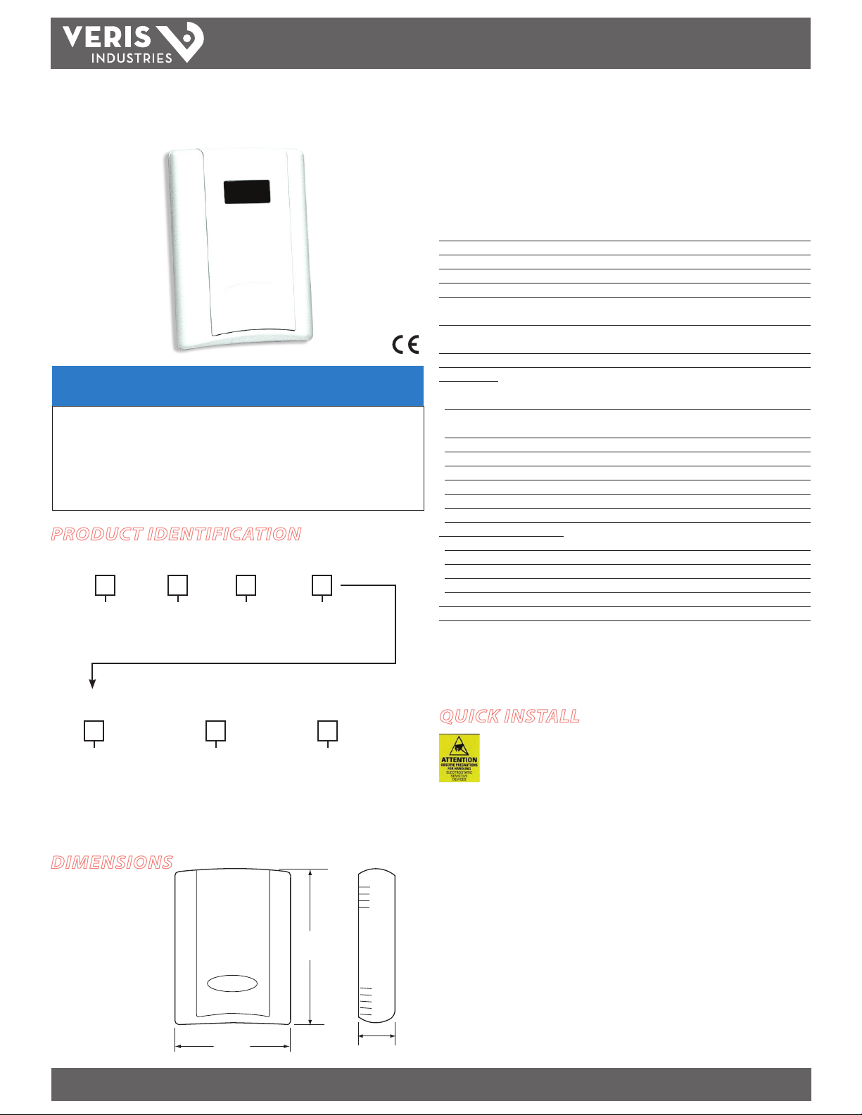
4.8"
(122 mm)
1.2"
(30 mm)
3.5"
(89 mm)
would not be covered under the factory warranty.
TM
HW Protocol HW Protocol
NOTICE
• This product is not intended for life or safety applications.
• Do not install this product in hazardous or classified locations.
• Read and understand the instructions before installing
this product.
• Turn off all power supplying equipment before working on it.
• The installer is responsible for conformance to all applicable codes.
PRODUCT IDENTIFICATION
Local Display
HW
L = LCD
X = No Display
Protocol
P
= Protocol
RH Option
1 = RH 1% NIST
2 = RH 2% NIST
H = RH 2%
Temp. Option
T
X = No temp. opti on
T = Temp. Transmitte r
INSTALLATION GUIDE
Wall Mounted Humidity Sensors
with Protocol Communication
Installer’s Specifications
Input Vol tage 12 to 30VDC, 24VAC; 100mA max.
Operating Temperature Range 0° to 50°C (32° to 122°F)
Housing Material High impac t ABS plastic , UL 94 VO
Protocol BACnet or Modbus (selectable)
Connection 2-wire RS- 485
Data Rate 9600, 19200, 38400, 57600 (Modb us), bps (selectable)
9600, 19200, 38400, 76800 (BACnet), bps (selectable)
Parity None/Odd/Even (selectable-Modbus)
None (BACnet)
Address Rang e 1-127
RH Transmitter:
HS Sensor Replaceable digitally proled thin-lm capacitive
(32-bit mathematic s); U.S. Patent 5,844,138
Accuracy* ±1% from 12 to 60% RH; ±2% from 10 to 80% RH;
NIST traceable multi-point calibration
Reset Rate** 24 hours
Stability ±1% @ 20°C (68°F) annually for two years
Hysteresis 1.5% typical
Operating Humidity Range 0 to 100% RH, noncondensing
Operating Temperature Range 10° to 35°C (50° to 95°F)
Temperature Coecient ±0.1% RH/°C above or below 25°C (typical)
Temperature Transmitter Option:
Sensor Type Solid-s tate, integrated circuit
Accuracy ±0.5°C (±1°F) typical
Resolution 0.1°C (0.2°F)
Range 10° to 35°C (50° to 95°F)
Setpoint Slider Resolution Option 1% full scale
Override Button Option Remotely readable and resettable
* Specied accuracy with 24VDC supplied power with rising humid ity.
** Reset rate is the time required to recover to 50% RH after ex posure to 90% RH for 24 hours.
Note: RTD/Thermistors in wall packages are not compensated for internal heating of product.
Temp. Cal. Cert.
Option
Housing
QUICK INSTALL
Observe handling precautions for static sensitive
X = No
1 = 1 pt. cal. cer t.*
2 = 2 pt. cal. cer t.*
3 = 3 pt. cal. cer t.*
* Only availab le if temperature option is sele cted.
DIMENSIONS
Blank = None
1 = Pushbut ton override
2 = Setpoi nt slider
3 = Pushbut ton override +
set point slider
Blank = Clou d white
B = Black
1. Select a mounting location away from ventilation sources. The sensor should be
2. Ax the backplate to the wall.
3. Wire the device. Refer to wiring diagram.
4. Install Cover.
Z205863-0C PAGE 1 ©2012 Veris Industries USA 800.354.8556 or +1.503.598.4564 / support@veris.com 01122
Alta Labs, Enercep t, Enspector, Hawkeye, Trustat, Veris, and the Veris ‘ V’ logo are trademark s or registered tradema rks of Veris Industries, L.L .C. in the USA and /or other count ries.
devices to avoid damage to the circuitry which
mounted on a vertical wall, about 4 1/2 feet above the oor.
Page 2
HW PROTOcOL
TM
INSTALLATION GUIDE
INSTALLATION
1. Remove the cover by pressing the tab at the top of the sensor while
pulling outward from the top of the cover.
2. Remove the backplate by unfastening the sensor from the bottom
of the backplate and pivoting the sensor outward.
3. Punch out openings in the backplate.
4. Position the sensor vertically on
the wall, 4 1/2 feet above the
oor.
correct
incorrect
Ground each unit via the power supply GND terminal or the RS-485 SHIELD terminal
if the power supply is oating. Grounding is necessar y to minimize common mode
voltage on the signal lines and to minimize radio frequency emissions that can
interfere with the operation of nearby radio equipment.
Daisy-chain devices with 120Ω termination resistors between RS-485+ and RS-485on the last device at each end of the chain. Maximum of 63 devices on one daisy
chain.
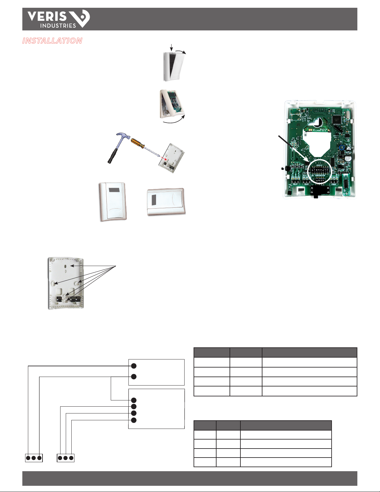
7. Congure the sensor.
Set the DIP switches on the backside of the
board.
DIP switches, located on backside o f board,
Top row: Address switches
Bottom row: Conguration switches
Select Address DIP switches
1. Up for Modbus, Down for BACnet.
2. Up to add 64 to network address.
3. Up to add 32 to network address.
4. Up to add 16 to network address.
5. Up to add 8 to network address.
5. Mount the backplate onto the wall using the screws provided.
Five screwholes available; use a minimum of two for secure mounti ng.
6. Wire the backplate.
Wire the RS-485 connections with shielded, twisted-pair wire, such as Belden Cable
1120A or equivalent. With 2-wire cable, connect the shield at one end only to the
RS-485 SHIELD terminal.
+
POWER SUPPLY
12-30VDC, 24VAC
-
CONTROL SYSTEM
COMMON
-
RS-485+
RS-485 -
SHIELD
PWR
GND
RS-485+
RS-485-
SHIELD
6. Up to add 4 to network address.
7. Up to add 2 to network address.
8. Up to add 1 to network address.
The network address is the sum of the values selected by placing switches 2
through 8 in their UP position. E.g.: If switches are D D D U D U D D, then BACnet
communication is selected, and the address is 16 + 4, for a total of 20. Valid Modbus
addresses are 1 to 127, and valid BACnet addresses are 0 to 127. Each device on the
daisy chain must have a unique address.
Select Configuration DIP switches
Conguration DIP switches 1 and 2 control the parity settings for Modbus and have
no eect on BACnet communication, which never has parity.
Switch 1 Switch 2 Parity
Down Down None (2 stop bits)
Down Up Odd
Up Up Even
Up Down None (1 stop bit; common but non-standard)
Conguration DIP switches 3 and 4 control the data rate for both Modbus and BACnet
modes.
Switch 3 Switch 4 Data Rate
Down Down 9600 bps
Down Up 19200 bps
Up D own 38400 bps
Up Up Modbus: 57600 bps; BACnet: 76800 bps
Z205863-0C PAGE 2 ©2012 Veris Industries USA 800.354.8556 or +1.503.598.4564 / support@veris.com 01122
Alta Labs, Enercep t, Enspector, Hawkeye, Trustat, Veris, and the Veris ‘ V’ logo are trademark s or registered tradema rks of Veris Industries, L.L .C. in the USA and /or other count ries.
Page 3

HW PROTOcOL
TM
Modbus Configuration
The list of supported Modbus function codes and the Modbus Point Map are in the
Point Map section of this document. The capabilities for controlling the TWxP are
identical with those for BACnet. The functions are summarized here.
Function Description
Coils Used to set temperature (Fahrenheit scale) and override button coil. *
Discrete
input
Input
registers
Holding
registers
* The temperature scale is maintained if power is lost. When delivered, temperature in Farenheit
and calibration lockout is on. Pressing th e override button turns the override button coil on. It can
only be turned o remotely.
** If any sensor option is not installed, th e reading for that sensor will be 0.
The various registers are still present even without the corresponding options
installed. In particular, the discrete input func tion can be used to see if the CO2
setpoint has been reached even if the relay is not in use.
BACnet Configuration
The list of BACnet objects and their implemented properties is in the BACnet
Descriptions section of this document. The capabilities for controlling the CWxP
are identical with those for the Modbus conguration. However, BACnet has some
additional protocol-related settings.
Indicates whether the relay is on.
Used to read the sensor options: RH (in units of 0.1%), temperature (in units
of 0.1°), and the slider (in units of %full scale). **
Used to specify the temperature oset and RH oset. Initial settings are 0°F,
and 0%, respectively. Settings are retained if power is lost.
INSTALLATION GUIDE
VISUAL INDICATORS
The RX light will ash while data is being received. If it isn’t blinking, it can indicate a
bad connection or that the RS-485+ and RS-485– wires are connected backwards.
The TX light will ash while data is being transmitted. For Modbus, if this light isn’t
blinking it can mean that the device isn’t being selected (wrong address) or the
communication parity or bit rate is set improperly.
In a BACnet installation, both the RX and TX lights will ash repeatedly even if no
communication is being per formed. In a Modbus installation, no lights will ash if
there is no communication activity.
MODBUS POINT MAP
Function code Function
01 Read coils
03 Read holding registers
04 Read input registers (if any sensor is not installed, the reading for that
sensor will be 0)
05 Write single coil
06 Write single register
07 Diagnostics (sub-function 00 returns quer y data)
15 Write multiple coils
16 Write multiple registers
17 Report slave ID (returns manufacturer, model name, and serial number)
All of these values correspond to BACnet objects with the same name. See the BACnet
Descriptions section for denitions.
The Device Object must have a unique name. This is set at the fac tory to the model
name, followed by the device’s serial number. The name can be changed if desired.
The device object must also have a unique object identier number. By default, this
is 133nnn where nnn is the current network address. This number can be changed
and the new number will be remembered. Setting the number to -1 (normally not
allowed) will reset the device to the default.
The Reliability property of the analog inputs for temperature, relative humidity, and
slider can be read to determine whether the device has these options installed.
8. Install the sensor onto the backplate.
9. When installation is complete, install the cover
and snap into place.
Coils
1 Fahrenheit (else Celsius)
2 Override (use override button to turn on)
Input Registers
1 Humidity (in tenths of a percent)
2 Temperature (in tenths of a degree; units set by coil 1)
3 Slider (in percent)
Holding Registers
1 Temp Oset (in tenths of a degree, current units)
2 RH oset (in tenths of a percent)
Z205863-0C PAGE 3 ©2012 Veris Industries USA 800.354.8556 or +1.503.598.4564 / support@veris.com 01122
Alta Labs, Enercep t, Enspector, Hawkeye, Trustat, Veris, and the Veris ‘ V’ logo are trademark s or registered tradema rks of Veris Industries, L.L .C. in the USA and /or other count ries.
Page 4

HW PROTOcOL
TM
BACNET DESCRIPTIONS
All properties read-only unless otherwise noted. Preserved means it is non-volatile.
Present_Value Range Restrictions
Object Name Minimum Value Maximum Value
Device_Instance 0 (but see description, above) 4,194,302
Temp_Oset -5 5
RH_Oset -10 10
Standard Object Types Supported
Object Type Supported Optional
Properties
Analog Input
-- AI
Analog Value
-- AV
Binary Value
– BV
Device -- DEV Description*, Location APDU_Timeout, Description, Location,
* Description is the same as the O bject_Identier. Reliability is “No Se nsor” if no sensor is installed
(applies to humidity, temperature, and slider).
Description*, Reliability
Description* Present_Value
Description* Present_Value
Objects Table
Object
Name
Humidity AI 1 Humidity in percent
Temperature AI 2 Temperature in Fahrenheit or Celsius
Slider AI 3 Slider position in percent.
Device_
Instance
Temp_
Oset
RH_Oset AV 3 Relative Humidity oset. Value rounded to the nearest tenth of
Fahrenheit BV 1 1 if temperature in Fahrenheit, 0 if in Celsius. Initially 1
Override BV 2 1 if override button pressed. Store 0 to reset. Initially 0. Volatile
Type and
Description of Present_Value Property
Instance
AV 1 Alternative way to change object_identier property of
AV 2 Temperature oset. Value rounded to nearest tenth of a
device. A negative value will restore the default device
instance (133nnn). Fractional values are truncated.
degree. Units are current units. Initial value is zero.
a percent. Initial value is zero.
Writable Properties
Max_Master, Object_Identier,
Object_Name
INSTALLATION GUIDE
Device Objects Table
Object
Name
HWxPxxx
CONFORMANCE STATEMENT
Vendor Name: Veris Industries
Product Name: Veris HWxP Environmental Sensor
Product Model Number: HWxPxxx
Application Software Version: 1
Firmware Revision: x.x
BACnet Protocol Revision: 2
Product Description: Environmental Sensor
BACnet Standardized Device Prole (Annex L): BACnet Application Specic Controller
(B-ASC)
List all BACnet Interoperability Building Blocks Supported (Annex K):
Segmentation Capability: Segmentation not supported
Standard Object Types Supported:
Data Link Layer Options: MS/TP master (Clause 9), baud rates: 9600, 19200, 38400,
76800
Device Address Binding: Static device binding is not supported. (No client functionality is included).
Networking Options: None
Character Sets Supported: ANSI X3.4
Type and
Instance
Device
133nnn
Object
Description
Property
Object_Identier
(R/W)
Object_Name
(R/W)
APDU_Timeout Default is 3000, maximum value is 60000
Max_Master Default is 127
Description Maximum length is 64 characters
Location Maximum length is 64 characters
Unique value where nnn initially is MS/TP
Unique name, initially a combination of
model and serial number. Maximum length
is 64 characters
DS-RP-B,DS-RPM-B,DS_WP-B,DM-DDB-B,DM-DOB-B,,DM-DCC-B
No dynamic creation or deletion supported
No proprietary properties or object types
(other information about objec ts on preceding pages)
Z205863-0C PAGE 4 ©2012 Veris Industries USA 800.354.8556 or +1.503.598.4564 / support@veris.com 01122
Alta Labs, Enercep t, Enspector, Hawkeye, Trustat, Veris, and the Veris ‘ V’ logo are trademark s or registered tradema rks of Veris Industries, L.L .C. in the USA and /or other count ries.
 Loading...