

Page 1
TM
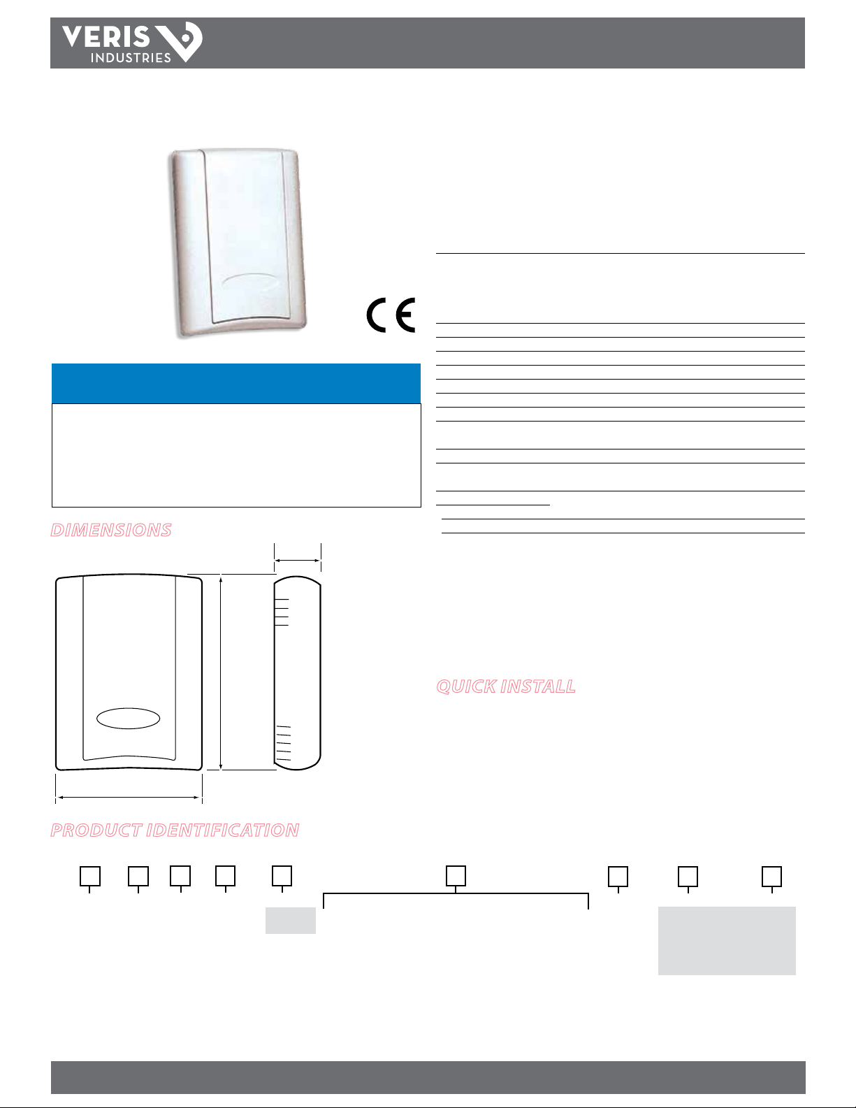
3.50"
(89 mm)
4.75"
(121 mm)
1.15"
(29 mm)
EnvironmEntal SEnSorS
HW SerieS HW SerieS
available
NOTICE
• This product is not intended for life or safety applications.
• Do not install this product in hazardous or classified locations.
• Read and understand the instructions before installing
this product.
• Turn off all power supplying equipment before working on it.
• The installer is responsible for conformance to all applicable codes.
Dimensions
inStallation GUiDE
Digital RH & RH/T Thermistor/RTD/Temp
Transmitter (Non-Display Model)
Installer’s Specifications
HS Element Digitally pr oled thin-lm capacitive (32 bit mathematics)
U.S. Patent 5,844,138
Accuracy at 25°C from 10-80% RH** Multi-point calibration; NIST traceable
±2%, 3%, or 5% models
±1% at 12-60% RH in voltage output mode
±1% at 20-40% RH in mA output mode
±1% at 12-60% RH in mA output mode with temp transmitter
Reset Rate* 24 hours
Stability ±1%@20°C (68°F) annually, for two years
Hysteresis 1.5% (typical)
Linearity Included in Accuracy spec.
Operating Humidit y Range 0 to 100% RH
Operating Temperature Range 10°C to 35°C (50°F to 95°F)
Temperature Coecient ±0.1% RH/°C above or below 25°C (typical)
Analog Output 4-20 mA mode: 2-wire, polarity insensitive
0-5V/0–10 V mode: 3-wire, obs erve polarity
Scaling 0-100% RH
Input Power 4-20 mA mode: loop powered 12-30 VDC only, 30 mA max.
0-5V/0-10 V mode: 12-30 VDC/24 VAC, 15 mA max.
Optional Temperature Output:
Transmitter Models Digital, 4-20mA/0-5/0-10V output, accuracy ±0.5°C (±0.9°F) typical
RTD Models Customer specied thermistor or RTD
EMC Confo rmance: EN61000-6 -3:2007 and A1:2011, EN61000 -6-1:2007
One side of transformer secondar y is connected to signal common. Isolation transformer or
dedicated power supply may be requ ired. To conform to EMC standards, shielded cabli ng and
technical information is availa ble from the factory upon request or is availa ble on our website:
www.veris.com
* Reset Rate is the time required to recover to 50% RH after e xposure to 90% RH for 24 hours.
** Specied accuracy with 24 VDC supplied power with rising hum idity.
RTD/Thermistors in wall packages are not compensated for internal heating of product.
quick install
1. Mount the sensor on a vertical wall, about 4½ feet above the oor, in a location
away from ventilation sources.
2. Ax the backplate to the wall.
3. Wire the device. Refer to wiring diagrams on page 2.
4. Install the cover.
ProDuct iDentification
NIST US or EU Temp. Sensor Type Display Accuracy
X
HW
= No display
1 = 1%
2 = 2%
3 = 3%
5 = 5%
N = NIST
X = No
Z202638-0W PAGE 1 ©2012 Veris Industries USA 800.354.8556 or +1.503.598.4564 / support@veris.com 07123
Alta Labs, Enercep t, Enspector, Hawkeye, Trustat, Veris, and the Veris ‘ V’ logo are trademark s or registered tradema rks of Veris Industries, L.L .C. in the USA and /or other count ries.
S = Standard
C = CE
T = Temp
X = No Temp
(Stop here)
A = Transmitte r: 10°-35°C
(50°-95°F) or 0°-50°C
(32°-122°F) (switchable)
B = 100R Platinu m, RTD
C = 1k Platinum, RTD
D = 10k T2, Therm istor
E = 2.2k, Ther mistor
F = 3k, Therm istor
G = 10k CPC, Ther mistor
H = 10k T3, Thermi stor
J = 10k Dale, Ther mistor
Temp. Cal. Cert. Option Value
K = 10k with 11k shunt, Ther mistor
M = 20k NTC, Ther mistor
N = 1800 ohm TAC, Therm istor
R = 10k US, Thermis tor
S = 10k 3A 221, Thermisto r
T = 100k, The rmistor
U = 20k, “D” T hermistor
W = 10k T2 high acc uracy, Thermist or
Y = 10k T3 high acc uracy, Thermist or
Z = 10k E1, Thermisto r
X = No Cert.
1 = 1 pt cal.
2 = 2 pt cal.
1 = Pushbut ton Override
2 = Setpoi nt Slider
3 = Pushbut ton Override
and Setpoint Slider
A = 1k
F = 10k
G = 20k
K = 50k
M = 100k
Page 2
TM
Observe precautions for handling static sensitive
POWER SUPPLY
12-24DC
CONTROL SYSTEM
COMMON
RH RETURN
T RETURN
RTD/THERMISTOR OVERRIDE
SETPOINT SLIDER
PWR (4-20 SEND)
RH OUT (4-20 RTN)
T OUT (4-20 RTN)
RTD/THERMISTOR OVERRIDE
RTD/THERMISTOR OVERRIDE
SLIDER RIGHT
SLIDER LEFT
SLIDER WIPER
+
-
-
POWER SUPPLY
24 VAC/DC
CONTROL SYSTEM
COMMON
RH INPUT 0-10V
T INPUT 0-10V
RTD/THERMISTOR/OVERRIDE
SETPOINT SLIDER
PWR
COMMON
RH OUT
T OUT
RTD/THERMISTOR/OVERRIDE
RTD/THERMISTOR/OVERRIDE
SLIDER RIGHT
SLIDER LEFT
SLIDER WIPER
+
-
-
HW SEriES
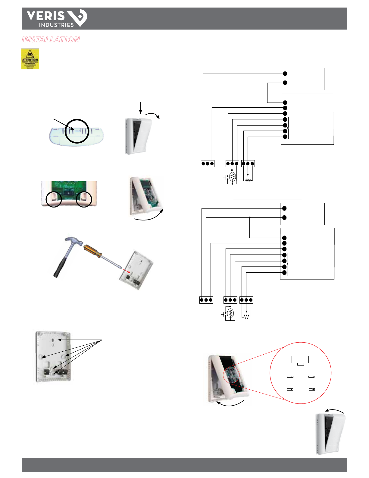
installation
devices to avoid damage to the circuitry that
is not covered under the factory warranty.
1. Locate the tab at the top of the sensor housing. Using only the minimum required
force, press this tab down and pull the cover outward from the top. Set the cover
aside.
Housing, Top View
Tab
2. Remove the backplate by unfastening the sensor from the bottom of the backplate
and pivoting the sensor outward.
inStallation GUiDE
6. Wire the backplate.
Current Output (2-Wire, 4-20mA)
3. Punch out wire opening in the backplate.
4. Position the backplate vertically on the wall, 4 ½ feet above the oor. Locate away
from windows, vents, and other sources of draft. If possible, do not mount on an
external wall, as this might cause inaccurate temperature readings.
5. Mount the backplate onto the wall using the screws provided.
Five screwholes available; use a minimum of two for secure mounti ng.
Voltage Output (3-Wire, 0-10V)
7. Install the sensor onto the backplate and use the switch to select voltage or current
output. Output selection must be correct before applying power to the sensor.
OUTPUT SELECT
VOLTS
RH OUT
10V 5V 10V 5V
T RANGE
50/95 32/122
8. When the installation is complete, replace the cover and snap it
into position.
mA
T OUT
T SCALE
C F
Z202638-0W PAGE 2 ©2012 Veris Industries USA 800.354.8556 or +1.503.598.4564 / support@veris.com 07123
Alta Labs, Enercep t, Enspector, Hawkeye, Trustat, Veris, and the Veris ‘ V’ logo are trademark s or registered tradema rks of Veris Industries, L.L .C. in the USA and /or other count ries.
 Loading...