

Page 1
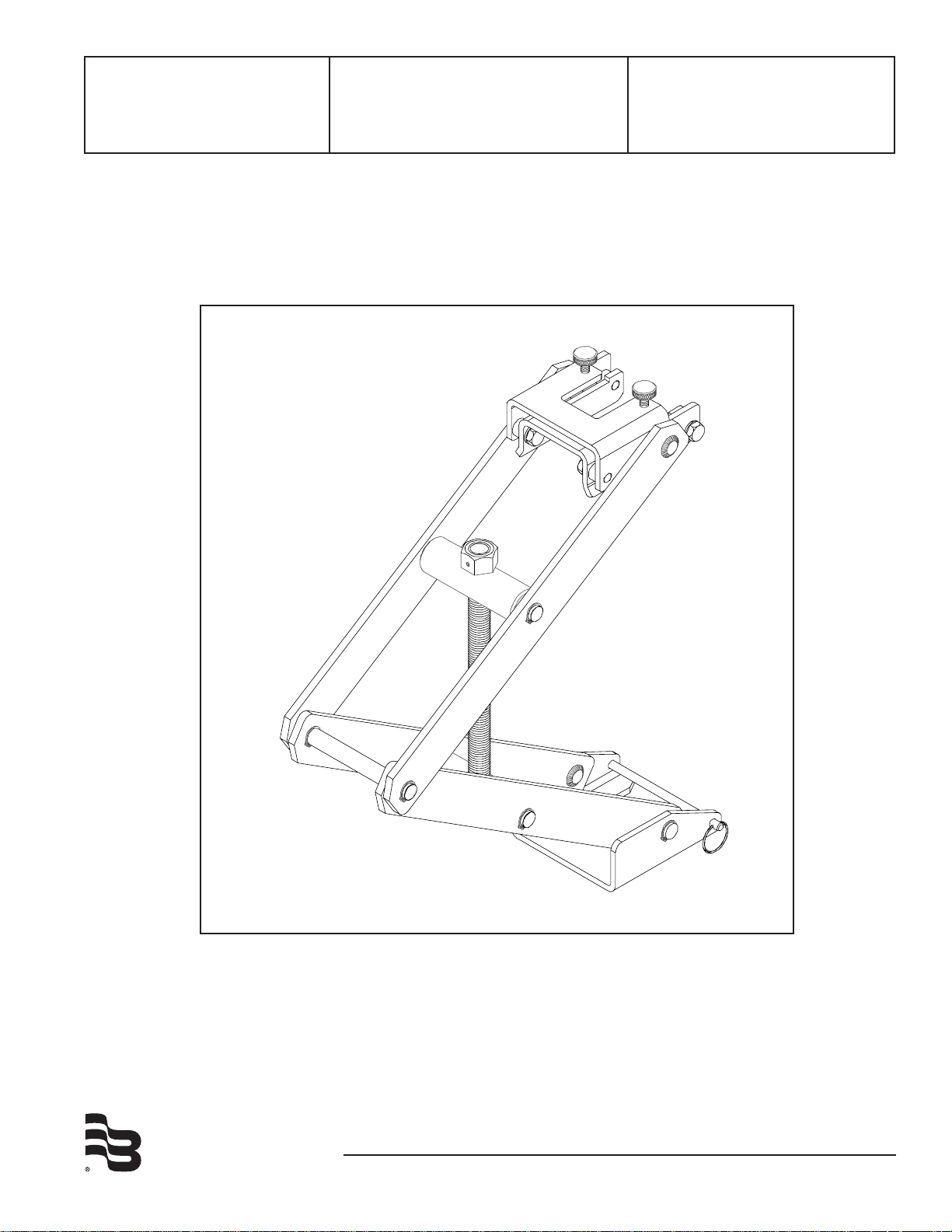
Model HTT
Hot Tap Tool for Badger®
Series 225/226 Flow Sensors
Installation &
Operation Manual
BadgerMeter, Inc.
872822
Rev. 6
4-09
Page 2
BLEED VALVE
HEX NUT
JAM NUT
Figure 1
Figure 2
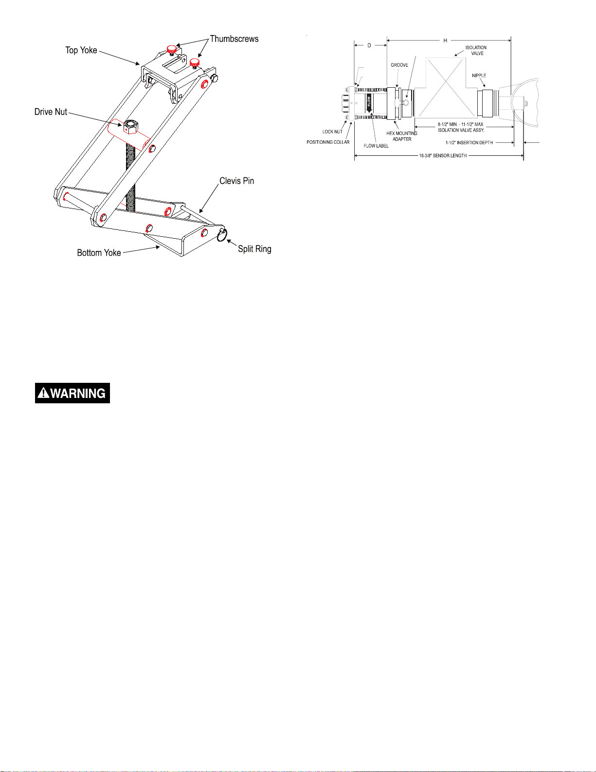
Installation into a pressurized pipeline
For pipe sizes 2½ inches and above, all Badger Meter
sensors are inserted 1 1/2 inches from the inside wall of
the pipe. The insertion depth is controlled by the position of
the hex nuts on the three threaded rods. The formula below
defines the distance between the top of the sensor hex
mounting adaptor and the bottom of the positioning collar
(the top of the hex nut). Reference figure 2.
The Model HTT Hot Tap Tool provides the mechanical
advantage required to safely insert and remove a Badger
Meter hot tap sensor from line pressure and provides a
restraint when removing the sensor from a pressurized pipe.
Removal of Badger® Series 225/226 from a pressurized
pipeline.
Do not remove lock nuts from
threaded rods above the positioning
collar without hot tap tool connected.
Serious injury could result.
1. Adjust Hot Tap tool opening by rotating drive nut with a
15/16 socket or box wrench (not provided) until the distance between the top and bottom yoke is approximately
equal to the distance between the groove on the hex
mounting adaptor and the bottom surface of the sensor
positioning collar.
2. Remove split ring and clevis pin.
3. Slide tool bottom yoke into the groove in the hex mounting
adaptor and secure with the clevis pin and split ring.
4. To permit clearance for the top yoke, lower two of the
three pairs of jam nuts under the sensor positioning collar
to a minimum of 1½ inchs below the positioning collar.
Then position the top yoke so the threaded rod with the
remaining jam nuts are centered in the yoke. Then slide
on the yoke, adjusting with drive nut as necessary.
5. Make sure the positioning collar is located in the recessed
area of the yoke by adjusting the drive nut until the top
yoke is snug against the bottom of the sensor positioning
collar. Then tighten thumb screws located on the top of
the tool.
6. Remove three lock nuts above the collar and slowly
withdraw sensor by rotating the drive nut of the tool
counterclockwise with a 15/16 socket or box wrench (not
supplied) until drive nut bottoms out on tool.
7. Close gate or ball valve fully.
8. Open bleed valve located on the hex mounting adaptor to
relieve pressure between valve and sensor.
9. Once all pressure is relieved remove tool and remove sensor from the hex adaptor.
D = 16 3/8” - ( H + Pipe Wall Thickness + 1.5 “ )
Example: If sensor is installed in a 8 inch Sch 80 pipe with a
pipe wall thickness of 0.5 inch and the “H” dimension is 10
inch then the calculation would be as below:
D = 16 3/8 - ( 10” + 0.5” + 1.5” )
D = 4 3/8”
1. Set one set of hex/jam nuts so that the distance between
the top surface of the hex nut and the top surface of
the hex mounting adaptor is equal to the “D” dimension
calculated above. Then adjust the other two sets of hex/
jam nuts 1½ inches below the first jam nut to allow
clearance for the tool top yoke.
2. Fully extend tool by turning drive nut counterclockwise
with a 15/16 inch socket or box wrench (not provided) until
drive nut contacts tool and slide the positioning collar into
the tool top yoke.
3. Remove the tool split ring and clevis pin and slide tool
bottom yoke into the groove on the sensor hex mounting
adaptor and secure by replacing the clevis pin and split
ring.
4. Mark sleeve 2 3/4 inchs from impeller end of metal sleeve.
This mark is a stopping point to insure that impeller/
bearing is not damaged. Open the bleed petcock valve
on the hex adapter to relieve the pressure resulting
from the sensor tube insertion. Carefully hand insert the
Badger Meter hot tap flow sensor sleeve assembly into
the hex mounting adapter until the mark lines up with the
top of the hex mounting adapter. At this point the sleeve
will have been inserted past the top two O-rings in the
adapter (approximately 1 - 1 1/4 inches). Take care not
to push the sensor past the mark on the sleeve as the
impeller could be damaged if it strikes the closed valve.
5. Rotate tool so the threaded rod with the adjusted hex/jam
nuts is centered in the top yoke of hot tap tool.
6. Rotate sensor sleeve so positioning collar holes align with
the threaded rods, and flow direction label is in general
direction making sure the positioning collar is located
in the recessed area of the top yoke. Slide the top yoke
2
Page 3

of the tool over the positioning collar and secure by
tightening the two thumbscrews on the top of the yoke.
7. Close the bleed petcock and slowly open the isolation
valve. Slowly turn the 15/16 inch drive nut clockwise to
insert the sensor tube assembly through the valve and
into the pipeline. Carefully guide the three threaded studs
of the hex mounting adapter through the holes of the
sensor positioning collar. Carefully lower the sensor until
the positioning collar contacts the hex nut preset for the
correct depth adjustment. Install the three lock nuts onto
the threaded rods, tightening only the lock nut on the
threaded rod with the preset hex/jam nut; then, bring the
two remaining lock nuts down until they just contact the
positioning collar. Do not tighten at this time
8. Remove the Model HTT Insertion/Removal Tool, by
loosening the two thumbscrews, removing the clevis pin
and then sliding the insertion tool off the sensor. Then
bring the two remaining sets of hex/jam nuts up to the
underside of the positioning collar, and tighten.
9. Align the sensor by first loosening the two set screws in
the side of positioning collar with a 3/32 inch Allen wrench.
Then align the sensor sight holes along the pipe axis
using the alignment rod provided in the sensor installation
kit. Ensure that the flow label arrow on the sensor
matches the liquid flow direction inside the pipe. Tighten
the positioning collar set screws. Note: As a backup to the
flow label arrow, there is a small hole located beside the
sight hole on the upstream side of the sensor.
3
Page 4

Badger® and Data Industrial® are registered trademarks of Badger Meter, Inc.
Due to continuous research, product improvements and enhancements, Badger
Meter reserves the right to change product or system specifications without notice,
except to the extent an outstanding contractual obligation exists.
Please see our website at www.badgermeter.com
for specific contacts.
Copyright © Badger Meter, Inc. 2009. All rights reserved.
BadgerMeter, Inc.
6116 E. 15th Street, Tulsa, Oklahoma 74112
(918) 836-8411 / Fax: (918) 832-9962
www.badgermeter.com
 Loading...