

Page 1
TM
HD SerieS
Digital RH and RH/T Transmitters
Availabl e
NOTICE
• This product is not intended for life or safety applications.
• Do not install this product in hazardous or classied locations.
• Read and understand the instructions before installing
this product.
• Turn off all power supplying equipment before working on it.
• The installer is responsible for conformance to all applicable codes.
No responsibility is assumed by Veris Industries for any consequences arising out of the
use of this material.
PRODUCT IDENTIFICATION
ENVIRONMENTAL SENSORS
Accuracy
HD
1 = 1%
2 = 2%
3 = 3%
5 = 5%
NIST
N = NIST
X = None
Output
M = 4-20mA
V = 0-5V/0-10VDC
US or EU Te mp.
S = Standard
C = CE
T = Temp
X = No Temp
(Stop here)
INSTALLATION GUIDE
SPECIFICATIONS
Input Power: *
Volt age Models 12-30VDC/24VAC, 15mA max.
mA Model loop powered 12-30VDC only, 30mA max.
Output Power:
Volt age Models 3-wire, obser ve polarity
mA Model 2-wire, not polarity sensitive (clipped and cappe d)
Humidity:
HS Element Digitally proled thin-lm capacitive (32-bit mathematics)
U.S. Patent No. 5,844,138
Accuracy @ 25°C from 10-80% RH** ±1%, ±2%, ±3%, or ±5% (specif y);
Multi-point calibration, NIST traceable
Temperature Eect, Duct Model +0.1% RH/°C above or below 25°C (typical)
Temperature Eect, Outdoor Model mA version: (0.0013x%RHx(T°C-2 5));
Volt version: (0.0015c%RHxT°C-25)) - (%RHx0.0008xabs(T°C-25 ))
Scaling 0-100% RH
Hysteresis 1.5% typical
Linearity Included in Accuracy spec.
Reset Rate*** 24 hours
Stability ±1% @ 20°C (68°F) annually, for two years
Temperature:
Optional Temperature Transmit ter Output Digital, 4-20mA (clipped and cappe d) or
0-5V/0-10V output;
HD transmit ter accuracy: ±0.5°C (±1.0°F) typical
Operating Environment:
Operating Humidity Range 0 to 100% RH noncondensing
Operating Temperature Range -40° to 50°C (-40° to 122°F)
Agency Approvals EMC EN 50081-1, EN 50082-1, EN 61000-4-4, EN 61000- 4-5,
EN 61000-4-3, ENV 50204, EN 61000-4-6
* One side of transformer secondar y is connected to signal common. Isolation transformer or
dedicated power supply may be requ ired.
** Specied accuracy with 24 VDC supplied power with rising hum idity.
*** Reset Rate is the time required to recover to 50% RH af ter exposure to 90% RH for 24 hours.
RTD Thermistors are not compenstated for internal heating of product.
To conform to EMC standards, shielded cabling and technical i nformation is available from the
factory upon reque st or is available on our website: www.veris.com
EMC Special Note: Connect this produc t to a DC distribution network or an AC/DC powe r adaptor
with proper surge protection (EN 61000-6-1:2007 specication requirements).
Humidity Transmitter Combination
OPTION
Sensor Type Range
A
= Transmitter
1 = -40° to 50 °C
(-40° to 122°F )
2 = 0° to 50°C
(32° to 122°F)
Temp Cert
Blank = None
1 =1pt Cal
2 = 2pt Cal
Humidity RTD/Thermistor Combination
OPTION
Sensor Type
B = 100R Platinu m, RTD
C = 1k Platinum, RTD
D = 10k T2, Therm istor
E = 2.2k, Ther mistor
F = 3k, Therm istor
G = 10k CPC, Ther mistor
H = 10k T3, Thermi stor
J = 10k Dale, Ther mistor
K = 10k with 11k shunt, Ther mistor
M = 20k NTC, Ther mistor
N = 1800 ohm TAC, Thermi stor
Q = 1uA/˚C, Linite mp
R = 10k US, Thermis tor
S = 10k 3A 221, Thermisto r
T = 100k, The rmistor
U = 20k “D”, Thermis tor
Temp Cert
Blank = None
1 =1pt Cal
2 = 2pt Cal
INSTALLATION
Observe precautions for handling static sensitive
devices to avoid damage to the circuitry that
is not covered under the factory warranty.
1. Choose a location on the return air duct.
2. Drill a 7/8” diameter hole in the duct for the sensor probe.
3. Mount the junction box housing to the duct using self-tapping screws (included).
4. Insert the probe through the black swage tting into the duct. Tighten the swage
tting.
5. Wire the probe (see the Wiring section). Leave wires at factory length to allow
for a service loop (to remove the sensor from junction box for service without
disturbing the conduit).
Z201380-0V PAGE 1 ©2013 Veris Industries USA 800.354.8556 or +1.503.598.4564 / support@veris.com 03132
Alta Labs, Ene rcept, Enspector, Hawk eye, Trustat, Aerospon d, Veris, and the Veris ‘V ’ logo are tradem arks or registe red trademarks o f Veris Industries, L .L.C. in the USA and/or ot her countries.
Page 2
TM
2.9"
(74 mm)
4.6"
(117 mm)
2.0"
(51 mm)
0.7"
(18 mm)
Foam Gasket
2.5" x 2.5"
(62 mm x 62 mm)
8.5"
(216 mm)
0.5" Dia.
(13 mm.)
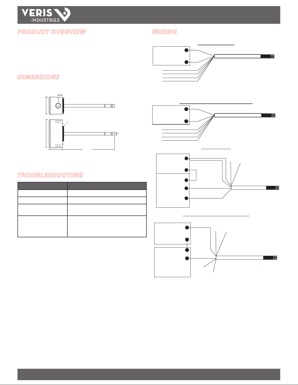
POWER SUPPLY
12 to 30 VDC/24 VAC
BLK
RED
BLUE 0-10V HUMIDITY
ORANGE 0-10V TEMP
GREEN 0-5V HUMIDITY
YELLOW 0-5V TEMP
–
+
POWER SUPPLY
12 to 30 VDC/24 VAC
BLK
RED
BLUE 0-10V HUMIDITY
GREEN 0-5V HUMIDITY
ORANGE THERMISTOR
ORANGE THERMISTOR
–
+
VDC
POWER SUPPLY
DIGITAL CONTROL
Temperature
4-20mA Return
(optional)
Humidity
4-20mA Return
BLUE
HUMIDITY
BLUE
HUMIDITY
White/Gray 0-1V
Test Leads for use
with voltmeter
ORANGE
TEMP
ORANGE
TEMP
+
–
–
VDC
POWER SUPPLY
DIGITAL CONTROL
Temperature
4-20mA Return
(optional)
Humidity
4-20mA Return
BLUE
HUMIDITY
BLUE
HUMIDITY
White/Gray 0-1V
Test Leads for use
with voltmeter
ORANGE
Thermistor
ORANGE
Thermistor
+
–
–
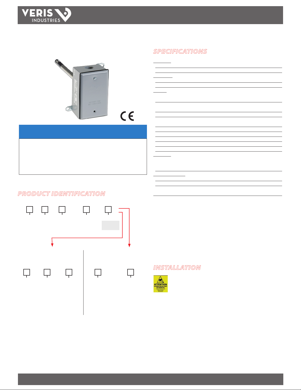
HD SERIES
INSTALLATION GUIDE
PRODUCT OVERVIEW
The HD Series duct-mounted humidity sensors provide high accuracy humidity
monitoring with a fully replaceable HS element for easy eld maintenance. NIST
certied accuracy and temperature sensing capability are available. The HD is
warranted for a period of ve years.
DIMENSIONS
WIRING
0-5V/0-10V Versions
NOTE: For 24 VAC transformer powered applicatio ns, one side of transformer secondary is
connected to common. Isolation transfor mer or dedicated power supply may be required.
0-5V/0-10V Versions with RTD/Thermistor
4-20mA Versions
TROUBLESHOOTING
Problem Solution
Filter tip does not t on probe HS element is backwards; reverse element.
Unit reads approx. 4.5mA HS element is backwards; reverse element.
Unit reads 100% with new
replacement sensor
Accuracy appears incorrect · Remove HS element while powered and verify output
Z201380-0V PAGE 2 ©2013 Veris Industries USA 800.354.8556 or +1.503.598.4564 / support@veris.com 03132
Alta Labs, Ene rcept, Enspector, Hawk eye, Trustat, Aerospon d, Veris, and the Veris ‘V ’ logo are tradem arks or registe red trademarks o f Veris Industries, L .L.C. in the USA and/or ot her countries.
Unit must be unpowered when installing a new sensor;
interrupt sensor power to restart.
goes to full scale.
· Verify voltage test leads on 4-20mA models
corresponds to the 4-20mA output.
4-20mA Versions with RTD/Thermistor
Page 3

TM
HD SERIES
INSTALLATION GUIDE
TEST POINTS AND SETUP VERIFICATION
0.42
1VDC
Voltmeter shows reading of 42% RH
WHITE (+)
For 4–20 mA versions: Test leads output 0-1 VDC corresponding to 0 to 100% RH
sensor reading. For example, a 0.42 VDC output on test points equals 42% RH sensor
reading. These test points also provide an output that veries the motherboard
accuracy when the HS element is removed. Connect test point leads to voltmeter
only. This output is not suitable for connection to a DDC panel.
To check the motherboard functionality using the test leads, remove the sensor
element. A 1.0 VDC reading veries motherboard functionality.
To verify sensor accuracy, de-power the unit and insert a replacement HS element.
Repower the unit and compare readings to the original sensor. For example, if test
points read 0.40 VDC (40% RH) with the original sensor, and 0.45 VDC (45% RH) with
the replacement sensor, then the original sensor is 5% o specication. This method
of ensuring accuracy oers more precision than using slings or other devices, and it
eliminates the need to manually adjust sensors to an unstable standard.
Note: Temperature, body sweat, and breath eect humidity. Ensure that conditions
are stable to evaluate performance.
The lter may be washed using warm water and a soft brush. Do not attempt to scrub
the HS element.
For 0-5V/0-10V versions, use the output as a test point and scale accordingly.
Test leads and voltmeter
verify accuracy and simpl ify
GRE Y(--)
DDC programming
SENSOR REPLACEMENT
Observe precautions for handling static sensitive
devices to avoid damage to the circuitry that
is not covered under the factory warranty.
1. Disconnect power to the unit.
2. Remove the probe from the junction box by loosening the black swage nut and
sliding it out.
3. Unscrew the lter on the tip of the probe. Set lter aside.
4. Remove the HS element by gently pulling from the pin connector. Do not attempt
to remove the temperature sensor adjacent to the HS element (if equipped).
5. Place a new HS element onto the pin connector. Orient as shown, or the unit will
not function (the lter will not screw on if the HS is inserted incorrectly).
Top
Side
Bottom
Side
6. Replace the lter. Re-insert the probe into the junction box and tighten the swage
nut.
Replacement HS Element Ordering Information
HS2xxx Replacement 2% HS Element, Duct
HS3xxx Replacement 3% HS Element, Duct
Temp Sensor
(if equipped)
Top S ide
Bottom Side
HS4xxx Replacement 5% HS Element, Duct
HS1Nx Replacement 1% HS NIST Element, Duct
HS2Nx Replacement 2% HS NIST Element, Duct
Replacement lters are provid ed with all elements. Order the appropriate ele ment accuracy to
match the motherboard accuracy for compatability.
Z201380-0V PAGE 3 ©2013 Veris Industries USA 800.354.8556 or +1.503.598.4564 / support@veris.com 03132
Alta Labs, Ene rcept, Enspector, Hawk eye, Trustat, Aerospon d, Veris, and the Veris ‘V ’ logo are tradem arks or registe red trademarks o f Veris Industries, L .L.C. in the USA and/or ot her countries.
 Loading...