

Page 1
TM
HAZARD OF ELECTRIC SHOCK, EXPLOSION, OR ARC FLASH
• Follow safe electrical work practices.
See NFPA 70E in the USA, or applicable local codes.
• This equipment must only be installed and serviced by qualified electrical personnel.
• Read, understand and follow the instructions before installing this product.
• Turn off all power supplying equipment before working on or inside the equipment.
• Use a properly rated voltage sensing device to confirm power is off.
DO NOT DEPEND ON THIS PRODUCT FOR VOLTAGE INDICATION
• Only install this product on insulated conductors.
Failure to follow these instructions will result in death or serious injury.
A qualied person is one who has skills and knowledge related to the construction and
operation of this electrical equipment and the installation, and has received safety
training to recognize and avoid the hazards involved. NEC2009 Article 100
No responsibility is assumed by Veris Industries for any consequences arising out of the
use of this material.
DANGER
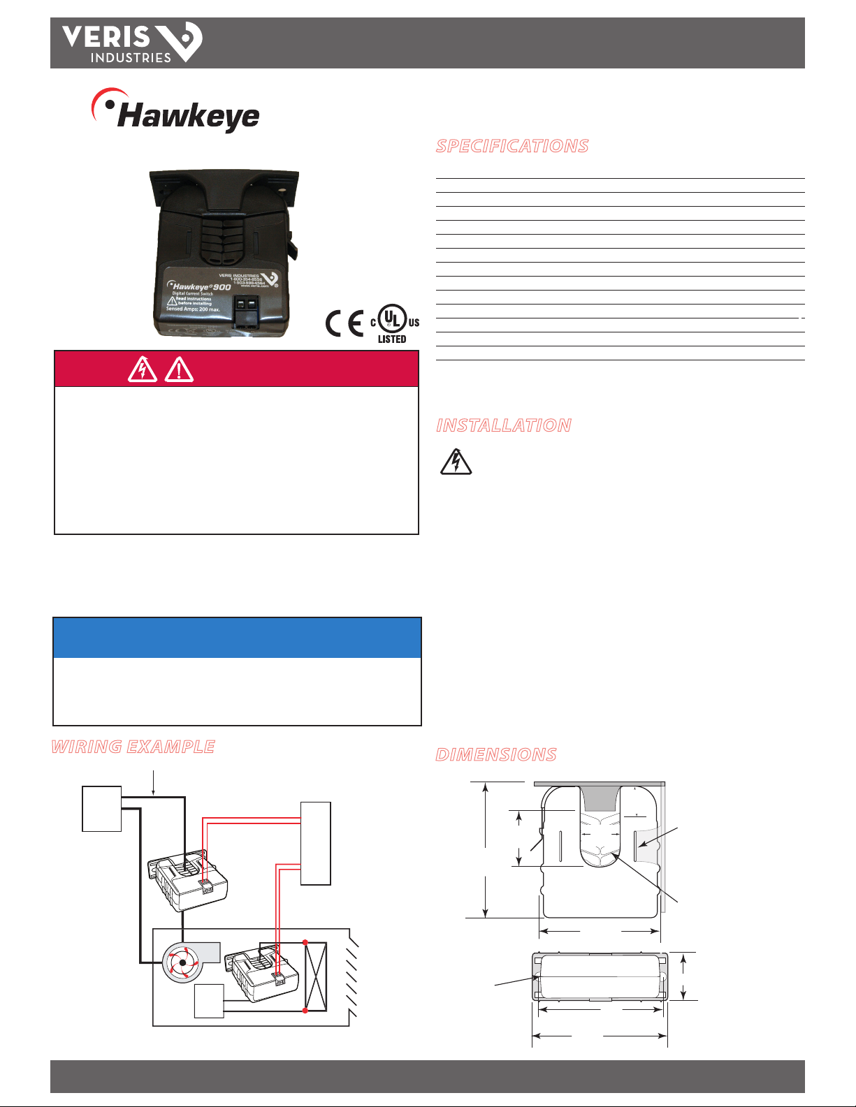
POWER
SOURCE
POWER
SOURCE
BUILDING AUTOMATION
CONTROLLER
UNIT VENT HEATER
DI
DI
Insulated Conductor Only
CURRENT MONITORING
TM
900
Split-Core Current Switch, Fixed Trip Point
INSTALLATION GUIDE
SPECIFICATIONS
Sensor Power Induced from monitored conductor
Amperage Range 1.5 - 200A Continuous
Status Output Ratings N.O. 1.0A@30VAC/DC not polarity sensitive
Insulation Class 600VAC RMS (UL), 300VAC RMS (CE)
Setpoint Fixed at 1.5A max. (60 Hz)
Frequency 50/60 H z
Temperature Range -15 ° to 60°C (5° to 14 0°F)
Humidity Range 10-90% RH non-condensing
O State Resis tance Open switch represents 1+ MΩ
On State Resistance Closed switch represents <200 mΩ
Terminal Block Wire Size 14 to 24 AWG (2.1 to 0.2 mm2)
Terminal Block Torque 3.5 to 4.5 in-lb (0.4 to 0.5 N-m)
Agency Approvals UL508, CE: EN61010-1
Installation Categor y Cat. III, pollution degree 2
For CE compliance, conductor shall be insul ated according to IEC 61010‑1.
INSTALLATION
NOTICE
• This product is not intended for life or safety applications.
• Do not install this product in hazardous or classified locations.
• The installer is responsible for conformance to all applicable codes.
• Mount this product inside a suitable fire and electrical enclosure.
WIRING EXAMPLE
Z201493-0D PAGE 1 ©2013 Veris Industries USA 800.354.8556 or +1.503.598.4564 / support@veris.com 03133
Alta Labs, Ene rcept, Enspector, Hawk eye, Trustat, Aerospon d, Veris, and the Veris ‘V ’ logo are tradem arks or registe red trademarks o f Veris Industries, L .L.C. in the USA and/or ot her countries.
Disconnect power to the enclosure containing the
conductor to be monitored.
1. Locate a surface for the removable mounting bracket that will allow the monitored
conductor to pass through the center window when it is installed and that
will keep the product at least ½” (13 mm) from any uninsulated conductors.
Determine cable routing for the controller connection, allowing wiring to reach
the mounting location.
2. Drill holes to mount the bracket to the chosen surface using the included screws.
3. Wire the output connections between the sensor and the controller (solid-state
contac t).
4. Snap the sensor over the wire to be monitored and clip the assembly to the
mounting bracket.
5. Secure the enclosure and reconnect power.
DIMENSIONS
Removable Mounting Bracket
3.1”
(79 mm)
Ø 0.3”
(8 mm)
1.1”
(26 mm)
(21 mm)
(70 mm)
3.0”
(76 mm)
0.8”
2.8”
2.5”
(64 mm)
1.0”
(25 mm)
Bracket can
be mounted
on three sides
for added
installation
exibility.
Self-gripping Iris
1.4”*
(36 mm)
Use DIN rail
mounting clip
(Veris part
number AH01) to
mount on stan‑
dard DIN rail.
Page 2
TM
H900
INSTALLATION GUIDE
OPERATION
The H900 is a current-sensitive switching device that monitors current (amperage)
in the conductor passing through it. A change in amperage in the monitored
conductor that crosses the switch (setpoint) threshold plus the hysteresis value
causes the resistance of the FET status output to change state, similar to the action
of a mechanical switch. In this model, the setpoint is xed at 1.5 A. The status output
is suitable for connec tion to building controller or other appropriate data acquisition
equipment operating at up to 30 volts. The H900 requires no external power supply
to generate its output.
The H900 housing oers unprecedented mounting exibility. The mounting bracket
can be attached in three dierent places. Additionally, the bracket is compatible with
the Veris AH01 DIN Rail clip, allowing DIN mounting.
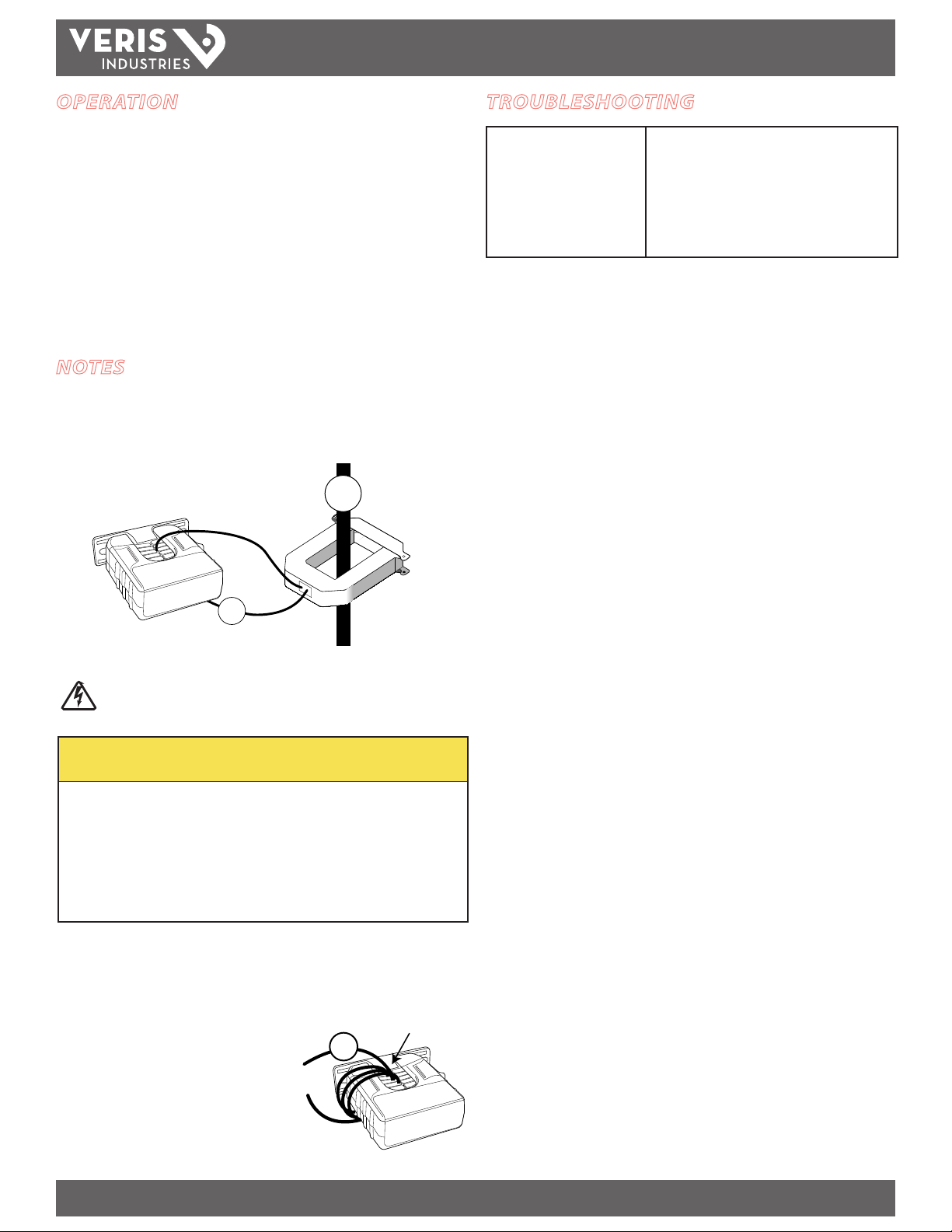
NOTES
For load currents greater than sensor maximum rating:
Use a 5 Amp (H68xx series) Current Transformer (CT) as shown. This technique can be
combined with wrapping (see below) to add range for a low current load on a high
current source.
> 200A (Sensor max.)
240A
TROUBLESHOOTING
No Reading at Controller • Check for amperage in monitored conductor (>1.5A).
• Check that amperage in the monitored conductor does
not exceed sensor max (200A).
• Check to be sure that no more than 30VAC/DC or 1.0A
has passed through the contact. Voltages or currents
above these levels will damage the unit.
• Verify that sensor core mating surfaces are clean and
that the core clamp is completely closed
5A
4A
300A:
H68xx‑5A CT
DANGER: 5A CTs can present hazardous voltages.
Install CTs in accordance with manufacturer's instructions.
Terminate the CT secondary before applying current.
CAUTION
RISK OF EQUIPMENT DAMAGE
• Derate the product’s maximum current for the number of turns
through the sensing window using the following formula.
Rated Max. Amps ÷ Number of Turns = Max. monitored Amps
e.g. : 100A ÷ 4 Turns = 25 Amps max. in monitored conductor
• Failure to follow these instructions can result in overheating
and permanent equipment damage.
For load currents less than sensor minimum rating:
Wrap the monitored conductor through the center window and around the sensor
body to produce multiple turns. This increases the current measured by the
transducer.
Program the controller to account for the extra
turns. e.g., if four turns pass through the sensor
(as shown), divide the normal controller reading
by 4.
<1.5 A (Sensor min.)
4x
1A
Z201493-0D PAGE 2 ©2013 Veris Industries USA 800.354.8556 or +1.503.598.4564 / support@veris.com 03133
Alta Labs, Ene rcept, Enspector, Hawk eye, Trustat, Aerospon d, Veris, and the Veris ‘V ’ logo are tradem arks or registe red trademarks o f Veris Industries, L .L.C. in the USA and/or ot her countries.
 Loading...