

Page 1
TM
the user will be required to correct the interference at his own expense.
NETWORK INTEGRATION
DANGER
HAZARD OF ELECTRIC SHOCK, EXPLOSION, OR ARC FLASH
• Follow safe electrical work practices. See NFPA 70E in the USA, or applicable local codes.
• This equipment must only be installed and serviced by qualified electrical personnel.
• Read, understand and follow the instructions before installing this product.
• Turn off all power supplying equipment before working on or inside the equipment.
• Use a properly rated voltage sensing device to confirm power is off.
DO NOT DEPEND ON THIS PRODUCT FOR VOLTAGE INDICATION
• Only install this product on insulated conductors.
Failure to follow these instructions will result in death or serious injury.
A qualied person is one who has skills and knowledge related to the construction and
operation of this electrical equipment and the installation, and has received safety
training to recognize and avoid the hazards involved. NEC2009 Article 100
No responsibility is assumed by Veris Industries for any consequences arising out of the
use of this material.
NOTICE
• This product is not intended for life or safety applications.
• Do not install this product in hazardous or classified locations.
• The installer is responsible for conformance to all applicable codes.
• Mount this product inside a suitable fire and electrical enclosure.
FCC PART 15 INFORMATION
NOTE: This equipment has been tested by the manufacturer and found
to comply with the limits for a class A digital device, pursuant to part
15 of the FCC Rules. These limits are designed to provide reasonable
protection against harmful interference when the equipment is
operated in a commercial environment. This equipment generates,
uses, and can radiate radio frequency energy and, if not installed and
used in accordance with the instruction manual, may cause harmful
interference to radio communications. Operation of this equipment in
a residential area is likely to cause harmful interference in which case
Modifications to this product without the express authorization of
Veris Industries nullify this statement.
Control system design must consider the potential failure modes of control paths and, for
certain critical control functions, provide a means to acheive a safe state during and after a
path failure. Examples of critical control functions are emergency stop and over-travel stop.
INSTALLATION GUIDE
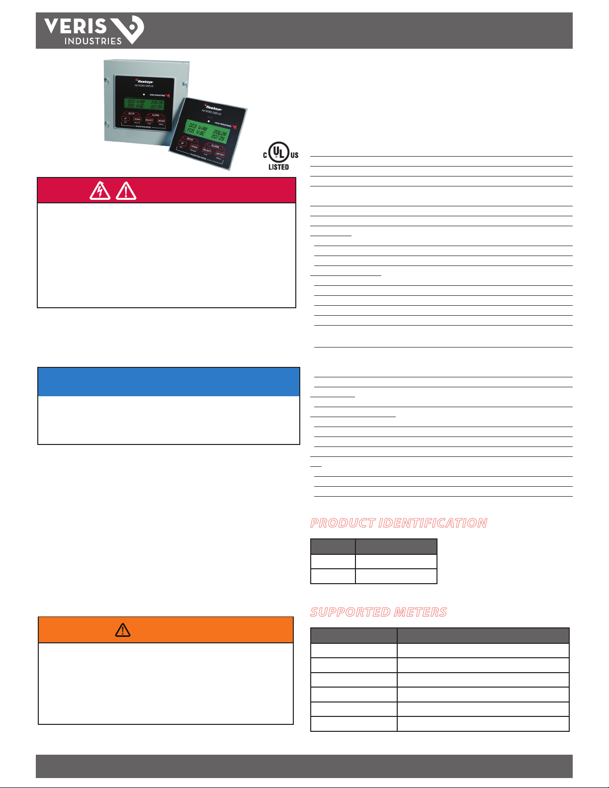
H8932/H8936
Network Display
Specifications
AC Power Source Dedicated 120/240 VAC, line-to-neutral; fused
Fuse Ratings 200mA at 250V 5x20 mm f ast blow
AC Power Voltage Tolerance 90-132VAC for 120V
AC Power Frequenc y 50/60 Hz
AC Power Termination 2-position Euro style pluggable connector
(max. wire size 12 gauge)
Terminal Block Torque 4.9 in-lb (0.56 N-m)
Alternate DC Power Source 12VDC, 300mA unfused
Environmental:
Operating Temperature Range 0° to 50°C (32° to 122°F)
Operating Humidity Range <95% RH, non-condensing
Storage Temperature Range -20° to 70°C (68° to 158°F)
Network Communications:
Interface Downstream: RS-485; Upstream: RS- 485, RS-232
Protocol Modbus RTU
Baud Rate UI-selectable 2400, 480 0, 9600, 19200
Parity UI-selectable NONE, ODD, EVEN
Communication Format 8-data-bits, 1-star t-bit, 1-stop-bit
RS-485 ¼ load transceivers; duplex is UI-selectable 2-wire or 4-wire;
5-position Euro-style pluggable connector
RS -232 (Upstream only) DCE, no handshaking; DB-9 connection;
pin 2: transmit ted data from display;
pin 3: received data to display; pin 5: ground
Terminal Block Torque 4.4 in-lb (0.5 N-m)
UI Switch In puts:
Number/Function 4 (Meter, Up, Down, Select)
Auxiliary Input (Remote Alarm):
Type Contact closure or pull-to-ground
Isolation Optical to 2500VAC
Sense UI-selec table N.O. or N.C.
Terminal Block Torque 3.5 to 4.4 in-lb (0.4 to 0.5 N-m)
LCD:
Size 1” x 4” visible area, 2 lines x 16 characters per line
Backlight Green, UI-adjustable br ightness in 10 steps
Status ( Tri-Color LED) Green = normal operation; Yellow = warning; Red = alarm
PRODUCT IDENTIFICATION
MODEL DESCRIPTION
H8932 without enclosure
H8936 with enclosure
SUPPORTED METERS
WARNING
LOSS OF CONTROL
∙ Assure that the system will reach a safe state during and after a control path failure.
∙ Separate or redundant control paths must be provided for critical control functions.
∙ Test the eect of transmission delays or failures of communication links.
∙ Each implementation of equipment using communication links must be individually
and thoroughly tested for proper operation before placing it in service.
Failure to follow these instructions may cause injury, death or equipment damage.
1
For additional information about anticipated transmission delays or failures of the link, refer to
NEMA ICS 1.1 (latest edition). Safety Guidelins for the Application, Installation, and Maintenance
of Solid-State Control or its equivalent in your specic country, language, and/or location.
Z202662-0G PAGE 1 ©2012 Veris Industries USA 800.354.8556 or 1.503.598.4564 / support@veris.com 09126
Alta Labs, Enercep t, Enspector, Hawkeye, Trustat, Veris, and the Veris ‘ V’ logo are trademark s or registered tradema rks of Veris Industries, L.L .C. in the USA and /or other count ries.
1
MODEL DESCRIPTION
H8035/H8036 Enercept Power Meter
H8163 with H8163-CB Energy Meter
H663/H704 Branch Circuit Meter
H8238 Multi-Circuit Monitor
E5xCx Power and Energy Meter, Modbus Protocol versions
E30/E31 Panelboard Monitoring System
Page 2
H8932/H8936
TM
OPERATION
The H8932/H8936 Network Display is designed to provide an easily visible display
for data collected by Modbus metering devices. The H893x is connected in series,
downstream from the Modbus master and upstream from the meters. All data values
collected by all supported meters are viewed, except for a limited data set for E3x
panelboard monitors. See the section titled Data Values for Supported Devices for
lists of data values that are presented on the Network Display.
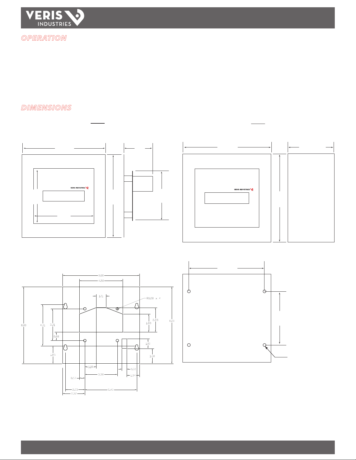
DIMENSIONS
INSTALLATION GUIDE
5.3”
(135 mm)
H8932
Front View Side View
8.0”
(204 mm)
8.0”
(204 mm)
5.8”
(147 mm)
Mounting plate template
(plate not provided with the H8932)
2.2”
(57 mm)
4.8”
(122 mm)
H8936
Front View Side View
8.0”
(204 mm)
8.0”
(204 mm)
Back View
7.0”
(177 mm)
4.2”
(106 mm)
5.0”
(128 mm)
4x Ø 0.28”
(7.1 mm)
Z202662-0G PAGE 2 ©2012 Veris Industries USA 800.354.8556 or 1.503.598.4564 / support@veris.com 09126
Alta Labs, Enercep t, Enspector, Hawkeye, Trustat, Veris, and the Veris ‘ V’ logo are trademark s or registered tradema rks of Veris Industries, L.L .C. in the USA and /or other count ries.
Page 3
TM
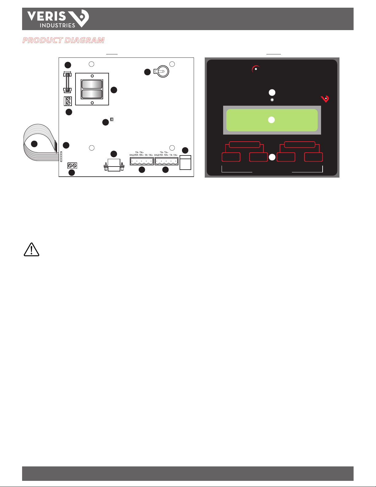
PRODUCT DIAGRAM
1
4
H8932/H8936
INSTALLATION GUIDE
BACK FRONT
2
3
5
Hawkeye
NETWORK DISPLAY
13
14
®
VERIS INDUSTRIES
12
6
8
7
9
10
1. 250 VAC 200 mA Fast Blow Fuse: Fused power connection for circuit
protection.
2. Lithium Battery: On board clock back up.
CAUTION! DANGER OF EXPLOSION IF BATTERY IS INCORRECTLY REPLACED. REPLACE ONLY WITH THE SAME OR
EQUIVALENT TYPE RECOMMENDED BY THE MANUFACTURER.
DISPOSE OF USED BATTERIES ACCORDING TO THE MANUFACTURER’S INSTRUCTIONS.
3. Power Transformer: Linear power supply for reliability and low noise.
4. 120 VAC Power Supply Terminals: 2-position Euro style pluggable connector
for 120 VAC, 60 Hz line to neutral power connection.
5. Auxiliary Input Status LED: Indicates alarm condition for the auxiliar y input.
SELECT
HOLD
ALARM
METER
SCROLL
11
SETUP
UP DOWN
NEXT
PREVIOUS
OPERATING MODE
15
13. Tri-Color LED: green = normal operation (no networked devices are in warning
or alarm mode); yellow = warning (one or more networked devices are in warning
mode); red = alarm (one or more networked devices are in alarm mode or the
auxiliary input is active).
14. LCD Display: Local data display; high resolution LCD with adjustable backlight
15. Membrane Keypad: Easy front-panel setup
6. Membrane Switch Pin Connector: Connection point for push button panel.
7. Auxiliary Input Contacts: Contact closure or pull-to-ground (10mA max.)
8. Upstream RS-232 Input Jack: Connection point for upstream RS-232 network.
9. Upstream RS-485 Connection Point: 5-position Euro style pluggable
connector for upstream RS-485 network. 2-wire or 4-wire selectable.
10. Downstream RS-485 Connection Point: 5-position Euro style pluggable
connector for downstream RS-485 network. 2-wire or 4-wire selectable.
11. 12 VDC Power Port: Alternate 12 VDC connection point for use with plug-in wall
mount transformer or power supply (auxiliary input is disabled if 12 VDC power is
used).
12. Membrane Switch Ribbon Cable
Z202662-0G PAGE 3 ©2012 Veris Industries USA 800.354.8556 or 1.503.598.4564 / support@veris.com 09126
Alta Labs, Enercep t, Enspector, Hawkeye, Trustat, Veris, and the Veris ‘ V’ logo are trademark s or registered tradema rks of Veris Industries, L.L .C. in the USA and /or other count ries.
Page 4
H8932/H8936
TM
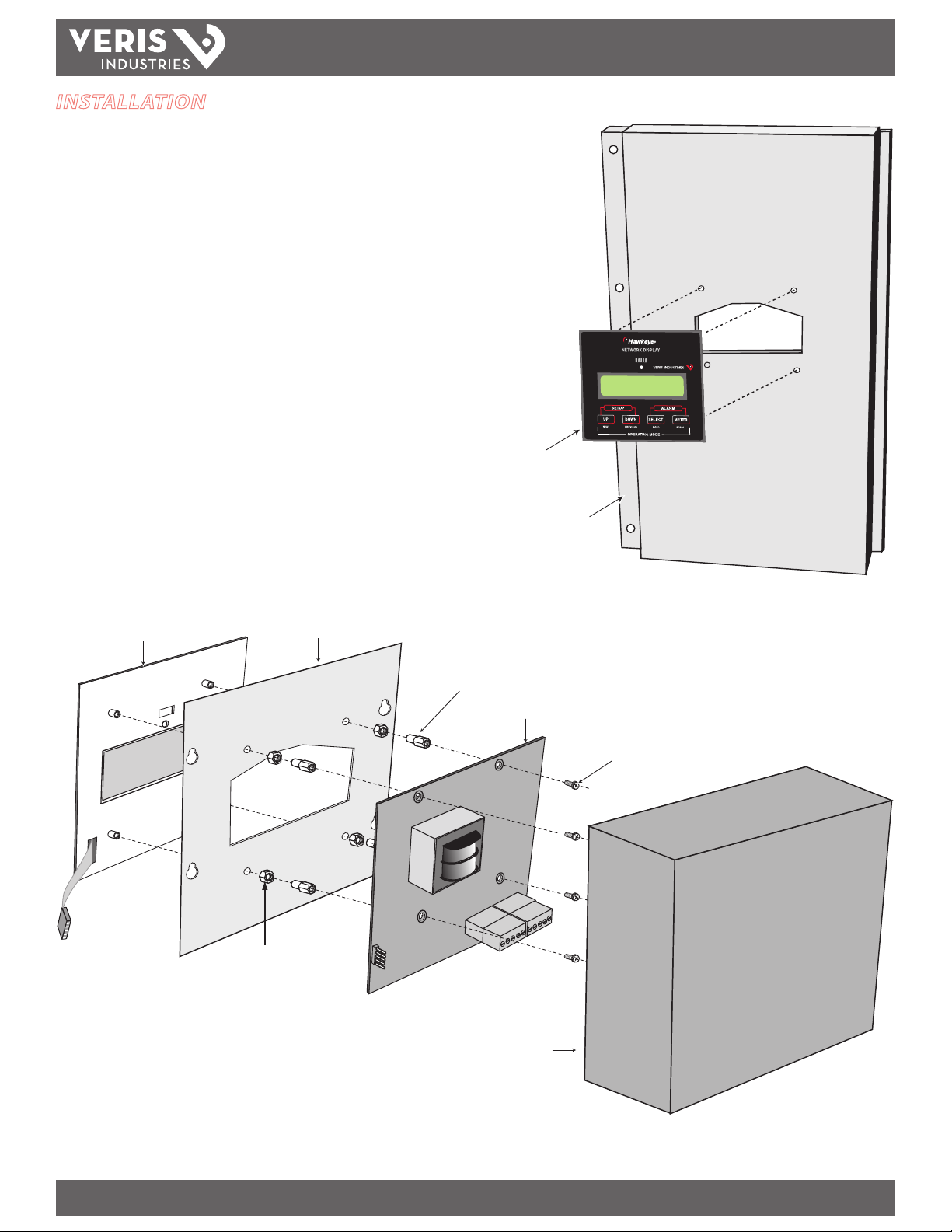
INSTALLATION
Component List
A. Face Plate with membrane switch ribbon cable
B. Box Lid (H8936 only) or panel (not included with H8932)
C. Threaded spacers (H8936 only)
D. Four threaded stand-os
E. Network Display
F. Four #6-32 screws
G. Box (H8936 only)
H8932 Mounting in a Panel (see right)
1. Drill 4 holes in the panel and cut out an area for the H8932.
2. Secure the faceplate by screwing the four threaded stand-os (D) into the face
plate studs from the inside of the door.
3. Attach the Network Display (E) to the threaded studs using four #6-32 screws (F)
provided.
4. Connect the membrane switch ribbon cable to the membrane switch pin
connector.
INSTALLATION GUIDE
Faceplate (A)
Panel (B)
H8932/H8936 Assembly Example:
Faceplate (A)
(4 ea.) Threaded Spacers (C)
(Provided with H8936 only)
Box Lid (H8936) or Panel (H8932)
(B)
(4 ea.) Threaded Stand-Os (D)
Network Display (E)
(4 ea.) #6-32 Screws (F)
Box (G) is provided with the
H8936 only (preassembled)
Z202662-0G PAGE 4 ©2012 Veris Industries USA 800.354.8556 or 1.503.598.4564 / support@veris.com 09126
Alta Labs, Enercep t, Enspector, Hawkeye, Trustat, Veris, and the Veris ‘ V’ logo are trademark s or registered tradema rks of Veris Industries, L.L .C. in the USA and /or other count ries.
Page 5

H8932/H8936
Control Panel
or PC
Next Network Display
On to additional Network Displays
Network Display
H663/H704
Branch Circuit Monitor
H8163 with H8163-CB
Energy Meter with
Communication Board
H8035/H8036
Enercept Power Meter
H8238
Multi-Circuit Monitor
E30/E31
Panelboard Monitor
E5xCx
Power and Energy Meter
End-of-Line
Termination Resistor
100 Ohms
Upstream RS-485
or
RS-232
Downstream RS-485
Up to 63 (physical) or 246 (logical) devices
UP DOWN
SELECT
METER
ALARM
OPERATING MODE
NETWORK DISPLAY
VERIS INDUSTRIES
SETUP
NEXT
PREVIOUS
HOLD
SCROLL
UP DOWN
SELECT
METER
ALARM
OPERATING MODE
NETWORK DISPLAY
VERIS INDUSTRIES
SETUP
NEXT
PREVIOUS
HOLD
SCROLL
Network Display
Downstream RS-485
H663/H704
Branch Circuit Monitor
H8163 with H8163-CB
Energy Meter with
Communication Board
H8035/H8036
Enercept Power Meter
H8238
Multi-Circuit Monitor
E30/E31
Panelboard Monitor
E5xCx
Power and Energy Meter
End-of-Line
Termination Resistor
100 Ohms
Up to 63 (physical) or 246 (logical) devices
TM
NETWORK CONFIGURATION
Wiring the Network(s)
The H8932/H8936 resides on a Modbus network as a pass-through device. Unlike
most Modbus RTU devices, it is not wired in a daisy chain conguration. This allows
the user to make separate upstream and downstream networks, allowing for exible
data retrieval, as the upstream options include RS-232 or RS-485.
Network Map: Option 1
INSTALLATION GUIDE
Network Map: Option 2
NOTE: The manufacturer does not recommend con necting multiple network displays in serie s on
the downstream network .
NOTE: Other Modbus devices must respond to the “Rep ort Slave ID” command (11h) to allow pass-
through communication from the upstream network.
Z202662-0G PAGE 5 ©2012 Veris Industries USA 800.354.8556 or 1.503.598.4564 / support@veris.com 09126
Alta Labs, Enercep t, Enspector, Hawkeye, Trustat, Veris, and the Veris ‘ V’ logo are trademark s or registered tradema rks of Veris Industries, L.L .C. in the USA and /or other count ries.
Page 6

H8932/H8936
TM
WIRING
1. Connect the upstream RS-485 or RS-232 devices (if used).
2. Connect the downstream RS-485 device daisy chain.
3. Connect the power. Use either 120 VAC (240 VAC if using the E model) 2-wire or 12
VDC as shown below.
4. Terminate the downstream and upstream networks per the RS-485 standard.
RS-232 Upstream
INSTALLATION GUIDE
Master (Network Display) Slave (Downstream Device)
Power Wiring Option #1
120 VAC
4-wire RS-485 Downstream
4-wire RS-485 Upstream
Master or Slave
2-wire RS-485 Downstream
2-wire RS-485 Upstream
Power Wiring Option #2*
12 V DC
*Internal fusing is not active o n the 12 VDC input. Do not connect
both power options at the sam e time.
External ½ A fuse must be provi ded by installer.
Z202662-0G PAGE 6 ©2012 Veris Industries USA 800.354.8556 or 1.503.598.4564 / support@veris.com 09126
Alta Labs, Enercep t, Enspector, Hawkeye, Trustat, Veris, and the Veris ‘ V’ logo are trademark s or registered tradema rks of Veris Industries, L.L .C. in the USA and /or other count ries.
Page 7

H8932/H8936
UP
DOWN
To Enter
(SELECT, DOWN, DOWN, SELECT, UP, UP)
UP
SELECT
DOWN
METER
Show next
submenu
Show previous
submenu
Return to
monitoring
Go to submenu
or start action
Setup Mode
Press Simultaneously
Press
Enter Password
* * * * * * *
Increment
parameter
Decrement
parameter
Return to
setup menu
Go to next
parameter
DOWN
UP
SELECT
METER
Increment
parameter
Decrement
parameter
Return to
setup menu
Go to next
parameter
DOWN
UP
SELECT
METER
Go to the next
parameter set.
Go to the previous
parameter set.
Go to the
next meter
Hold a reading on
the LCD (display will
ash).
For use in automatic
cycle mode (See Setup
Operations).
The current reading does
not update, allowing time
to manually record the
reading. Press any
other button to release
the held reading.
DOWN
UP
SELECT
METER
Go to the
next alarm.
Reset the currently
displayed alarm.
Exit the alarm
display.
To Enter
Alarm Menu
Press Simultaneously
Press
UP
SELECT
SELECT
METER
METER
TM
SETUP
Use the Setup mode to initialize and congure the display to the application
requirements. Use Setup Sub-menus to group parameters for setup.
Entering Setup Mode
Setup Mode Sub-Menus
After entering the password (Select, Down, Down, Select, Up, Up), the device enters
the Setup Mode Sub-Menus. Scroll through these menus using the Up or Down
buttons, and enter a menu by pressing Select.
1. VIEW SYSTEM INFO: Lists the model number and rmware version of the device.
INSTALLATION GUIDE
Status LED and Relay Operation
The status LED displays the condition of the alarm registers on a color cue basis.
Green: normal operation (no networked devices are in warning or alarm
mode)
Yellow: warning (one or more networked devices are in warning mode)
Red: alarm (one or more networked devices are in alarm mode or the
auxiliary input is active).
Monitoring Mode
Monitoring mode is the default mode for the H8932/H8936. In monitoring mode, the
data values are updated at 4-second intervals. The H8932/H8936 can be set either
to cycle automatically through all parameters on all devices or to display a selected
parameter continuously.
2. FIND METERS: Initiates a search and identies meters on the network. Exit the
search by pressing any key (do not exit until all active addresses have been
counted). Unsupported devices are designated as “unknown device,” and
parameters are not displayed.
3. REVIEW METERS: Review all meters on the network.
4. SETUP COMMUNICATIONS: Scroll through this list of available parameters using
the Select button; change a parameter value using the Up and Down buttons.
Communications Parameters:
Address Routing (On, O)
Modbus Address (1-247)
Upstream Type (RS-485, RS-232)
Upstream Duplex (2-wire, 4-wire) (not available for RS-232)
Upstream Baudrate (2400, 4800, 9600, 19200)
Upstream Parity (NONE, ODD, EVEN)
Downstream Duplex (2-wire, 4-wire)
Downstream Baudrate (2400, 4800, 9600, 19200)
Downstream Parity (NONE, ODD, EVEN)
5. SETUP OPERATION: Scroll through this list of available parameters using the Select
button; select a parameter value using the Up and Down buttons.
Alarm Mode
Alarm Mode provides a means of viewing and resetting warnings and alarms on the
downstream network. To enter Alarm mode, press the Select and Meter buttons
simultaneously.
Operation Parameters:
Z202662-0G PAGE 7 ©2012 Veris Industries USA 800.354.8556 or 1.503.598.4564 / support@veris.com 09126
Backlight Brightness (0-9; 0 = o)
Auxiliary Input (open, closed)
Rotate Parameters (Yes, No)
Alta Labs, Enercep t, Enspector, Hawkeye, Trustat, Veris, and the Veris ‘ V’ logo are trademark s or registered tradema rks of Veris Industries, L.L .C. in the USA and /or other count ries.
Page 8

TM
MAIN MENU NAVIGATION
H8932/H8936
INSTALLATION GUIDE
Default Mode
To Enter
Press Simultaneously
Press
To Enter
Press Simultaneously
Enter Password
MONITORING
UP
Show next
parameter set
ALARM MENU
UP
Show next
alarm
SETUP MENU
UP
* * * * * * *
DOWN
Show previous
parameter set
DOWN
SELECT
Hold reading
SELECT
SELECT
Clear alarm Return to
(SELECT, DOWN, DOWN, SELECT, UP, UP)
METER
next meter
METER
METER
monitoring mode
Go to
Press
UP
Show next
sub-menu
DOWN
Show previous
sub-menu
SELECT
Enter a sub-menu
or start action
METER
Return to
monitoring mode
Z202662-0G PAGE 8 ©2012 Veris Industries USA 800.354.8556 or 1.503.598.4564 / support@veris.com 09126
Alta Labs, Enercep t, Enspector, Hawkeye, Trustat, Veris, and the Veris ‘ V’ logo are trademark s or registered tradema rks of Veris Industries, L.L .C. in the USA and /or other count ries.
Page 9

TM
SUB-MENU NAVIGATION
H8932/H8936
INSTALLATION GUIDE
1st Sub-menu:
View System Info
2nd Sub-menu:
Find Meters
3rd Sub-menu:
Review Meters
SELECT
Enter the sub-menu
DOWNUP
Scroll parameters:
Model Number/Serial Number
Version/Revision
Memory/Clock
SELECT
Find Meters
SELECT
Review Meters
UP
Scroll through meters
METER
Return to setup menu
METER
Return to setup menu
METER
Return to setup menu
4th Sub-menu:
Setup Communications
5th Sub-menu:
Setup Operation
SELECT
Enter the sub-menu
SELECT
Scroll parameters:
Address Routing (On, O)
Modbus Address (1-247)
Upstream Type (RS-485, RS-232)
Upstream Duplex (2-wire, 4-wire) (not available for RS-232)
Upstream Baudrate (2400, 4800, 9600, 19200)
Upstream Parity (NONE, ODD, EVEN)
Downstream Duplex (2-wire, 4-wire)
Downstream Baudrate (2400, 4800, 9600, 19200)
Downstream Parity (NONE, ODD, EVEN)
SELECT
Enter the sub-menu
SELECT
Scroll parameters:
Backlight Brightness (0-9; 0=O)
Auxiliary Input (open, closed)
Rotate Parameters (Yes, No)
METER
Return to setup menu
METER
Return to setup menu
Increment
Parameter
Increment
Parameter
DOWNUP
Decrement
Parameter
DOWNUP
Decrement
Parameter
Z202662-0G PAGE 9 ©2012 Veris Industries USA 800.354.8556 or 1.503.598.4564 / support@veris.com 09126
Alta Labs, Enercep t, Enspector, Hawkeye, Trustat, Veris, and the Veris ‘ V’ logo are trademark s or registered tradema rks of Veris Industries, L.L .C. in the USA and /or other count ries.
Page 10

H8932/H8936
TM
DATA VALUES FOR SUPPORTED DEVICES
H8035 Enercept Power Meter
INSTALLATION GUIDE
H8163 Energy Meter with H8163-CB Board
Display* Units* Description Modbus Address
KWH kWh Energy Consumption 258/259
KW kW Real Power 260/261
H8036 Enercept Power Meter
Display* Units* Description Modbus Address
KWH kWh Energy Consumption 257/258
KW kW Real Power 261/262
KVA R kVAR Reactive Power 263/264
KVA kVA Apparent Power 265/266
PF --- Power Factor 267/268
V-LL Volts Average Voltage, L-L 269/270
V-LN Volts Average Voltage, L-N 271/272
AMPS Amps Average Current 273/274
KW-A kW Real Power, Phase A 275/276
KW-B kW Real Power, Phase B 277/278
KW-C kW Real Power, Phase C 279/280
PF-A --- Power Factor, Phase A 281/282
PF-B --- Power Factor, Phase B 283/284
PF-C --- Power Factor, Phase C 285/286
V-AB Volts Voltage, Phase A-B 287/288
V-BC Volts Voltage, Phase B-C 289/290
V-AC Volts Voltage, Phase A-C 291/292
V-AN Volts Voltage, Phase A-N 293/294
V-BN Volts Voltage, Phase B-N 295/296
V-CN Volts Voltage, Phase C-N 297/298
AM PA Amps Current, Phase A 299/300
AMPB Amps Current, Phase B 301/302
AMPC Amps Current, Phase C 303/304
AVE kW Average Real Power 305/306
MIN kW Minimum Real Power 307/308
MAX kW Maximum Real Power 309/310
Display* Units* Description Modbus Address
KWH kWh Energy Consumption 257/258
KW kW Real Power 261/262
KVA R kVAR Reactive Power 263/264
KVA kVA Apparent Power 265/266
PF --- Power Factor 267/268
V-LL Volts Average Voltage, L-L 269/270
V-LN Volts Average Voltage, L-N 271/272
AMPS Amps Average Current 273/274
KW-A kW Real Power, Phase A 275/276
KW-B kW Real Power, Phase B 277/278
KW-C kW Real Power, Phase C 279/280
PF-A --- Power Factor, Phase A 281/282
PF-B --- Power Factor, Phase B 283/284
PF-C --- Power Factor, Phase C 285/286
V-AB Volts Voltage, Phase A-B 287/288
V-BC Volts Voltage, Phase B-C 289/290
V-AC Volts Voltage, Phase A-C 291/292
V-AN Volts Voltage, Phase A-N 293/294
V-BN Volts Voltage, Phase B-N 295/296
V-CN Volts Voltage, Phase C-N 297/298
AM PA Amps Current, Phase A 299/300
AMPB Amps Current, Phase B 301/302
AMPC Amps Current, Phase C 303/304
* The prex (k) changes to M or G for very la rge readings.
Z202662-0G PAGE 10 ©2012 Veris Industries USA 800.354.8556 or 1.503.598.4564 / support@veris.com 09126
Alta Labs, Enercep t, Enspector, Hawkeye, Trustat, Veris, and the Veris ‘ V’ logo are trademark s or registered tradema rks of Veris Industries, L.L .C. in the USA and /or other count ries.
Page 11

H8932/H8936
TM
INSTALLATION GUIDE
H663 and H704 Branch Circuit Monitors
Display Units Description Modbus Address
CH01 Amps Current, Channel 1 1
CH02 Amps Current, Channel 2 2
CH03 Amps Current, Channel 3 3
CH04 Amps Current, Channel 4 4
CH05 Amps Current, Channel 5 5
CH06 Amps Current, Channel 6 6
CH07 Amps Current, Channel 7 7
CH08 Amps Current, Channel 8 8
CH09 Amps Current, Channel 9 9
CH10 Amps Current, Channel 10 10
CH11 Amps Current, Channel 11 11
CH12 Amps Current, Channel 12 12
CH13 Amps Current, Channel 13 13
CH14 Amps Current, Channel 14 14
CH15 Amps Current, Channel 15 15
CH16 Amps Current, Channel 16 16
CH17 Amps Current, Channel 17 17
CH18 Amps Current, Channel 18 18
CH19 Amps Current, Channel 19 19
CH20 Amps Current, Channel 20 20
CH21 Amps Current, Channel 21 21
CH22 Amps Current, Channel 22 22
CH23 Amps Current, Channel 23 23
CH24 Amps Current, Channel 24 24
CH25 Amps Current, Channel 25 25
CH26 Amps Current, Channel 26 26
CH27 Amps Current, Channel 27 27
CH28 Amps Current, Channel 28 28
CH29 Amps Current, Channel 29 29
CH30 Amps Current, Channel 30 30
CH31 Amps Current, Channel 31 31
CH32 Amps Current, Channel 32 32
CH33 Amps Current, Channel 33 33
CH34 Amps Current, Channel 34 34
CH35 Amps Current, Channel 35 35
CH36 Amps Current, Channel 36 36
CH37 Amps Current, Channel 37 37
CH38 Amps Current, Channel 38 38
CH39 Amps Current, Channel 39 39
CH40 Amps Current, Channel 40 40
CH41 Amps Current, Channel 41 41
CH42 Amps Current, Channel 42 42
H8238 Multi-Circuit Monitor
Display* Units* Description Modbus Address
KWH kWh Energy Consumption 258/259
KW kW Real Power 260/261
KVA R kVAR Reactive Power 262/263
KVA kVA Apparent Power 264/265
PF --- Power Factor 266/267
V-LL Volts Average Voltage, L-L 268/269
V-LN Volts Average Voltage, L-N 270/271
AMPS Amps Average Current 272/273
FREQ Hz Frequency 274/275
KW-A kW Real Power, Phase A 276/277
KW-B kW Real Power, Phase B 278/279
KW-C kW Real Power, Phase C 280/281
PF-A --- Power Factor, Phase A 282/283
PF-B --- Power Factor, Phase B 284/285
PF-C --- Power Factor, Phase C 286/287
V-AB Volts Voltage, Phase A-B 288/289
V-BC Volts Voltage, Phase B-C 290/291
V-AC Volts Voltage, Phase A-C 292/293
V-AN Volts Voltage, Phase A-N 294/295
V-BN Volts Voltage, Phase B-N 296/297
V-CN Volts Voltage, Phase C-N 298/299
AM PA Amps Current, Phase A 300/301
AMPB Amps Current, Phase B 302/303
AMPC Amps Current, Phase C 304/305
AVE kW Average Real Power 308/309
MIN kW Minimum Real Power 310/311
MAX kW Maximum Real Power 312/313
* The prex (k) changes to M or G for very la rge readings.
Z202662-0G PAG E 11 ©2012 Veris Industries USA 800.354.8556 or 1.503.598.4564 / support@veris.com 09126
Alta Labs, Enercep t, Enspector, Hawkeye, Trustat, Veris, and the Veris ‘ V’ logo are trademark s or registered tradema rks of Veris Industries, L.L .C. in the USA and /or other count ries.
Page 12

H8932/H8936
TM
INSTALLATION GUIDE
E50Cx Power and Energy Meter
Display* Units* Description Modbus Address
KWH kWh Energy Consumption 259/260
KW kW Real Power 261/262
KVA R kVAR Reactive Power 263/264
KVA kVA Apparent Power 265/266
PF --- Power Factor 267/268
V-LL Volts Average Voltage, L-L 269/270
V-LN Volts Average Voltage, L-N 271/272
AMPS Amps Average Current 273/274
KW-A kW Real Power, Phase A 275/276
KW-B kW Real Power, Phase B 277/278
KW-C kW Real Power, Phase C 279/280
PF-A --- Power Factor, Phase A 281/282
PF-B --- Power Factor, Phase B 283/284
PF-C --- Power Factor, Phase C 285/286
V-AB Volts Voltage, Phase A-B 287/288
V-BC Volts Voltage, Phase B-C 289/290
V-AC Volts Voltage, Phase A-C 291/292
V-AN Volts Voltage, Phase A-N 293/294
V-BN Volts Voltage, Phase B-N 295/296
V-CN Volts Voltage, Phase C-N 297/298
AM PA Amps Instantaneous Current, Phase A 299/300
AMPB Amps Instantaneous Current, Phase B 301/302
AMPC Amps Instantaneous Current, Phase C 303/304
FREQ Hz Frequency, derived from Phase A 307/308
KVA H kVAh Apparent Energy Consumption 309/310
KVRH kVARh Reactive Energy Consumption 311/312
KVA A kVA Apparent Power, Phase A 313/314
KVA B kVA Apparent Power, Phase B 315/316
KVAC kVA Apparent Power, Phase C 317/318
KVRA kVAR Reactive Power, Phase A 319/320
KVRB kVAR Reac tive Power, Phase B 321/322
KVRC kVAR Reactive Power, Phase C 323/324
PDKW kW Total Real Power Present Demand 325/326
PDKR kW Total Reactive Power Present Demand 327/328
PDKA kW Total Apparent Power Present Demand 329/330
MDKW kW Total Real Power Max. Demand 331/332
MDKR kW Total Reactive Max. Present Demand 333/334
MDKA kW Total Apparent Max. Present Demand 335/336
* The prex (k) changes to M or G for very la rge readings.
E51Cx Power and Energy Meter
Display* Units* Description Modbus Address
KWH kWh Accumulated Real Energy: Net (Import -
KVA H kVAh Apparent Energy: Net (Import - Export) 271/272
KW kW Total Net Instantaneous Real Power 277/278
KVA R kVAR Total Net Instantaneous Reactive Power 279/280
KVA kVA Total Net Instantaneous Apparent Power 281/282
PF --- Power Factor 283/284
V-LL Volts Average Voltage, L-L 285/286
V-LN Volts Average Voltage, L-N 287/288
AMPS Amps Average Current 289/290
FREQ Hz Frequency 290/291
PUL 1 kW Pulse Counter 1 (Import Real Energy) 313/314
PUL 2 kW Pulse Counter 2 (Export Reactive Energy) 315/316
KW-A kW Real Power, Phase A 365/366
KW-B kW Real Power, Phase B 367/368
KW-C kW Real Power, Phase C 369/370
KVRA kVAR Reactive Power, Phase A 371/372
KVRB kVAR Reac tive Power, Phase B 373/374
KVRC kVAR Reactive Power, Phase C 375/376
KVA A kVA Apparent Power, Phase A 377/378
KVA B kVA Apparent Power, Phase B 379/380
KVAC kVA Apparent Power, Phase C 381/382
PF-A --- Power Factor, Phase A 383/384
PF-B --- Power Factor, Phase B 385/386
PF-C --- Power Factor, Phase C 387/388
V-AB Volts Voltage, Phase A-B 389/390
V-BC Volts Voltage, Phase B-C 391/392
V-AC Volts Voltage, Phase A-C 393/394
V-AN Volts Voltage, Phase A-N 395/396
V-BN Volts Voltage, Phase B-N 397/398
V-CN Volts Voltage, Phase C-N 399/400
AM PA Amps Instantaneous Current, Phase A 401/402
AMPB Amps Instantaneous Current, Phase B 403/404
AMPC Amps Instantaneous Current, Phase C 405/406
PDKW kW Total Real Power Present Demand 293/294
PDKR kW Total Reactive Power Present Demand 295/296
PDKA kW Total Apparent Power Present Demand 297/298
MDWI kW Total Real Power Max. Demand 299/300
MDRI kW Total Reactive Power Max. Demand 301/302
MDAI kW Total Apparent Power Max. Demand 303/304
MDWE kW Total Real Power Max. Demand 305/306
MDRE kW Total Reactive Power Max. Demand 307/308
MDAE kW Total Apparent Power Max. Demand 309/310
Export)
257/258
Z202662-0G PAGE 12 ©2012 Veris Industries USA 800.354.8556 or 1.503.598.4564 / support@veris.com 09126
Alta Labs, Enercep t, Enspector, Hawkeye, Trustat, Veris, and the Veris ‘ V’ logo are trademark s or registered tradema rks of Veris Industries, L.L .C. in the USA and /or other count ries.
Page 13

H8932/H8936
TM
E3x Panelboard Monitoring System
The E3x meters collec t a large amount of data, but only a subset of this data is presented on the H8932/H8936
Network Display, based on phase conguration and model type.
Phase Conguration:
The H8932/H8936 can be congured to display single, two, or three phased readings from the E3x meter,
based on the value selected in Modbus register 536.
Register 536 Value Display Configuration
0 or 1 = Single phase Single phase setup displays channel 1-42
2 = Two phase Two phase setup displays channel 1-21
3 = Three phase Three phase setup displays channel 1-14
Model Type:
INSTALLATION GUIDE
Display* Units* Description
Mains
FREQ Hz Frequency, Phase A
V-AN Volts Voltage, Phase A-N
V-BN Volts Voltage, Phase B-N
V-CN Volts Voltage, Phase C-N
V-AB Volts Voltage, Phase A-B
V-BC Volts Voltage, Phase B-C
V-AC Volts Voltage, Phase A-C
AUX KWH kWh Aux. Total Energy
AUX KW kW Aux. Total Real Power, Phases A, B, C
AUX PF --- Aux. Total Power Factor
AUX AMPS Amps Aux. Average Current, Phases A, B, C
Branch Circuits (1 to 42), Single Phase (xx = channel number, 1 through 42)
Mxx KWH kWh Energy
Mxx KW kW Real Power
Mxx PF --- Power Factor
Mxx AMPS Amps Current
Branch Circuits (1 to 42), Two Phase (xx = channel number, 1 through 42)
Mxx KWH kWh Energy
Mxx KW kW Real Power
Mxx PF --- Power Factor
Mxx AMPS Amps Current
Branch Circuits (1 to 42), Three Phase (xx = channel number, 1 through 42)
Mxx KWH kWh Energy
Mxx KW kW Real Power
Mxx PF --- Power Factor
Mxx AMPS Amps Current
Model
A B C
• •
• •
• •
• •
• •
• •
• •
• •
• •
• •
• • •
•
•
•
• • •
•
•
•
• • •
•
•
•
• • •
Modbus Address
600/601
606/607
608/609
610/611
612/613
614/615
616/617
618/619
620/621
622/623
624/625
2000 to 2083
2084 to 2167
2168 to 2251
2252 to 2335
5000 to 5041
5042 to 5083
5084 to 5125
5126 to 5167
8000 to 8027
8028 to 8055
8056 to 8083
8084 to 8111
* The prex (k) changes to M or G for very la rge readings.
Z202662-0G PAGE 13 ©2012 Veris Industries USA 800.354.8556 or 1.503.598.4564 / support@veris.com 09126
Alta Labs, Enercep t, Enspector, Hawkeye, Trustat, Veris, and the Veris ‘ V’ logo are trademark s or registered tradema rks of Veris Industries, L.L .C. in the USA and /or other count ries.
 Loading...