

Page 1
TM
the user will be required to correct the interference at his own expense.
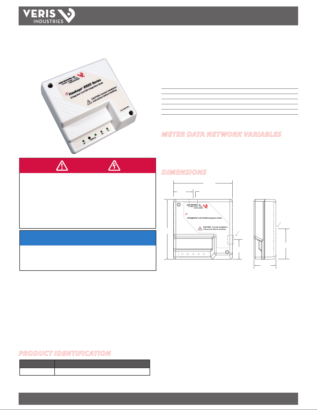
4.25"
(108 mm)
2.12
(54 mm)
1.16"
(30 mm)
4.25"
(108 mm)
1.53"
(39 mm)
C
L
C
L
C
L
Wire Opening
Wire Opening
Wire Opening
1.16"
(30 mm)
SERVICE TX RX
MODBUS
OP
Hawkeye® 8920 Series
POWER MONITORING
INSTALLATION GUIDE
H8920-5
DANGER
HAZARD OF ELECTRIC SHOCK, EXPLOSION, OR ARC FLASH
• Follow safe electrical work practices. See NFPA 70E in the USA, or applicable local codes.
• This equipment must only be installed and serviced by qualified electrical personnel.
• Read, understand and follow the instructions before installing this product.
• Turn off all power supplying equipment before working on or inside the equipment.
• Use a properly rated voltage sensing device to confirm power is off.
DO NOT DEPEND ON THIS PRODUCT FOR VOLTAGE INDICATION
• Only install this product on insulated conductors.
Failure to follow these instructions will result in death or serious injury.
H8920-5
LONTalk Integration Node
For Use With Enercept H8035 Power Meters
Installer’s Specifications
LonWor ks® Network Free topolog y transceiver, 78 kbps
Modbus Network RTU 9600 BAUD, 8N1 format
Network Variable Type Float
Input Power 16-24 VAC/DC, 100mA (max.)
Temperature Range 0 to 60°C (32 to 140°F)
Humidity Range 0 - 95% non-condensing
METER DATA NETWORK VARIABLES
kWh, Consumption
kW, Real Power
DIMENSIONS
NOTICE
• This product is not intended for life or safety applications.
• Do not install this product in hazardous or classified locations.
• The installer is responsible for conformance to all applicable codes.
• Mount this product inside a suitable fire and electrical enclosure.
FCC PART 15 INFORMATION
NOTE: This equipment has been tested by the manufacturer and found
to comply with the limits for a class A digital device, pursuant to part
15 of the FCC Rules. These limits are designed to provide reasonable
protection against harmful interference when the equipment is
operated in a commercial environment. This equipment generates,
uses, and can radiate radio frequency energy and, if not installed and
used in accordance with the instruction manual, may cause harmful
interference to radio communications. Operation of this equipment in
a residential area is likely to cause harmful interference in which case
Modifications to this product without the express authorization of
Veris Industries nullify this statement.
PRODUCT IDENTIFICATION
H8920-5 Enercept® H8035 to LonTalk® integration node
Z204 057-0B PAGE 1 ©2011 Veris Industries USA 800.354.8556 or +1.503.598.4564 / support@veris.com 07111
Alta Labs, Enercep t, Enspector, Hawkeye, Trustat, Veris, and the Veris ‘ V’ logo are trademark s or registered tradema rks of Veris Industries, L.L .C. in the USA and /or other count ries.
MODEL DESCRIPTION
Page 2
H8920-5
TB1
TB2
TB3
TB4
OP
POWER MB
+
SHIELD B A
SERVICE
RX
TX
TB5
TB6
TB7
TB8
-
LON
TM
INSTALLATION GUIDE
OPERATION
The H8920-5 LONTalk Integration Node allows the integration of Veris Industries
Enercept H8035 Series power meters with a LON Works control/monitoring system.
The H8920-5 converts the 2 power metering data network variables collected by the
H8035 as Modbus protocol to LONTalk. Using an indexing technique, the H8920-5
reports the data from up to 63 H8035 Enercept meters on the downstream Modbus
network. Adjusting an input variable allows selection of the Modbus address of the
desired meter. The data is then recorded before selecting another Enercept. The
H8920-5 can also be used for binding purposes with a single H8035 meter.
The H8920-5 polls the H8035 meter for its full data set approximately once
per second. All output data network variables are immediately updated with
this received data. Data exchanged between the node and the meter are fully
checksummed to ensure integrity. If corrupt data is detected, the output network
variables are not updated and retain their previous value.
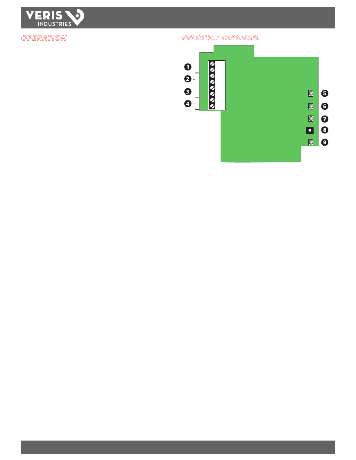
PRODUCT DIAGRAM
1. LON Talk Terminal Block: Connect to the LON network at these terminals. This
connection is not polarity sensitive.
2. Shield Terminal Block: Communications shielding for both the LONTalk and
Modbus communications networks.
3. Modbus Terminal Block: Connect to the Enercept Modbus network. This
connection is polarity sensitive; ensure correct polarity.
4. 16-24 VAC/DC Power: Two-wire system power terminal block.
5. TX LED: Indicates transmission of Modbus network data
6. RX LED: Indicates reception of Modbus network data
7. Service LED: Standard LON Works Ser vice LED. Used in concert with the Service
Switch to locally view the commissioning status of the device. LED status af ter the
service switch is pushed:
ON, then OFF solid = Device has been commissioned by a network tool.
BLINK at 1/2 Hz rate = Device has not been commissioned by a network tool.
ON, OFF, then solid ON = Device does not have an application.
8. Identification Service Switch: Standard LonWorks Service Switch. Used in
concert with the Service LED to locally view the commissioning status of the
device.
9. OP LED: Normally on. The OP LED will blink o when there is an incomplete data
exchange between the meter and the LON node. If this LED is always o, then
the meter is not responding to data requests (i.e., the meter is disconnected,
unpowered, or incorrectly wired).
Z204 057-0B PAGE 2 ©2011 Veris Industries USA 800.354.8556 or +1.503.598.4564 / support@veris.com 07111
Alta Labs, Enercep t, Enspector, Hawkeye, Trustat, Veris, and the Veris ‘ V’ logo are trademark s or registered tradema rks of Veris Industries, L.L .C. in the USA and /or other count ries.
Page 3

H8920-5
TM
INSTALLATION GUIDE
INSTALLATION
1. Remove screws from the lid of the H8920-5 housing. Lift lid and remove wire guide
caps. Set aside with the lid.
2. Bring the H8035 RS-485 network cable to the
Modbus terminal block marked +MB-. Thread
wires through wire guide before terminating.
Connect the (+) to TB6. Connect the (-) wire to
TB5. Connect the shield wire to TB4.
3. Bring the LON Works network cable to the
terminal block marked BA LON. Thread wires
through wire guide before terminating. Connect
the A wire to TB1. Connect the B wire to TB2.
Connect the LON network shield wire to TB3.
4. Connect the 16-24 VAC/DC power wires to TB7 and TB8. The power terminals are
not polarity sensitive. This power source must be separate and isolated from other
circuits to prevent unwanted "ground loops."*
5. Thread wires through the most convenient openings in the housing.
6. Re-attach the lid and snap wire guides into place. Replace screws to hold the
housing together.
7. Mount the H8920-5. The device can be ush mounted to a wall, screw mounted to
a 2 or 4s electrical encosure, or nipple mounted to an existing enclosure. Mount
the H8920-5 in a class 2 environment.
8. Refer to the H8035 installation instructions for connec tion of the LON node to the
H8035 power meter.
* Veris transformers such as X020xxx, X040 xxx or X050xxx or DC power sup plies such as PS-24-7.5,
15, or 30 fulll these requirements. If the installatio n only has non-isolated 24 VAC available, then
a Veris transformer such as X020ADA can provide the necessary isolation.
LON A
LON B
Shield
Modbus –
Modbus +
Power
TB1
TB2
TB3
TB4
TB5
TB6
TB7
TB8
CONFIGURATION
1. Upon powering up, the OP-LED is lit.
2. During operation, the OP-LED turns o if either of the following occurs:
a) No Modbus requests are generated by the unit for 10 seconds. This occurs
with new units (which have yet to be commissioned) or any units which
are in "Uncongured," "O-Line" or "Disabled" LonTalk states. Under these
conditions, the neuron chip will not generate requests to the Modbus
network.
b) No response or an error response from the Modbus network (e.g. no meter
attached, wrong type of meter (H8036 instead of H8035), broken RS-485
wir es, etc.).
3. If the OP-LED is OFF for any reason covered in step 2 above, it will be re-lit when a
correct response is received from the Modbus network.
4. Under Condition 2b above, the oating-point SNVT data will be replaced with
oating-point-not-a-number (NaN,0x7FC00000), indicating to the remote user
that the data is no longer valid.
Index Feature
By adjusting the network input variable nviMeter Index, the Modbus address used to
populate all of the NVOs can be changed. This option is used to view and archive
data from a Modbus network of up to 63 H8035 power meters. Using this feature
eliminates the possibility of binding any points from the node. If the application
requires binding, the LON node can only view one meter.
Using the Meter-Index function
To ensure that the data read from the unit corresponds to the correct meter, follow
this algorithm:
1. Change nviMeter Index to the desired meter.
2. Wait for nvoMeter Index to change to the same value as nviMeter Index. Do
not read data from the unit until this occurs: You will not be able to determine
which meter the data corresponds to until nvoMeter Index=nviMeter Index.
Do not use "time-delays" to wait for the new data to be valid.
3. Once nvoMeter Index=nviMeter Index, you may poll values with the
assurance that the data corresponds to the desired meter.
Power Meter Configuration
If binding is required, use Modbus address 1 for the H8035 power meter if binding is
required. When employing the indexing method, use addresses 1-63. Please refer to
the H8035 Installation Instructions for meter addressing information.
Auto Propagate Feature
The H8920-5 automatically propagates all network variables. If nciMaxSendTg is
set above zero (default is zero), all variables are propagated periodically. Units are
in tenths of a second. For example, if nciMaxSendTg is set to 100, the H8920-5 will
automatically propagate all variables every 10 seconds.
Z204 057-0B PAGE 3 ©2011 Veris Industries USA 800.354.8556 or +1.503.598.4564 / support@veris.com 07111
Alta Labs, Enercep t, Enspector, Hawkeye, Trustat, Veris, and the Veris ‘ V’ logo are trademark s or registered tradema rks of Veris Industries, L.L .C. in the USA and /or other count ries.
Page 4

H8920-5
Up to 63 H8035s
H8920-5 LON Node
LON Talk® Network
Modbus Network
Lon Talk®
Controller
TM
INSTALLATION GUIDE
NETWORK OPTIONS
Resetting the Energy Accumulator
To reset the Energy Accumulator nvoEgyWH, use the input network variable nviEgyClr
and follow this procedure:
1. Ensure that nviEgyClr.state > 0 & nviEgyClr.value > 0. Default is {1,1}.
2. Set nviEgyClr.state = 0 & nviEgyClr.value = 0.
3. Set nviEgyClr.state = 1 & nviEgyClr.value = 1.
At step 3, the H8920-5 issues an energy accumulator reset command to the H8035.
Once cleared, the meter will continue to count kWh from zero until another reset is
commanded.
Resetting the Average/Minimum/Maximum Power Variables
Reset the power variables (nvoAvePower, nvoMinPower, and nvoMaxPower) to
instantaneous power by following this procedure:
1. Ensure that nviPwrClr.state > 0 & nviPwrClr.value > 0Default is {1,1}.
2. Set nviPwrClr.state = 0 & nviPwrClr.value = 0.
3. Set nviPwrClr.state = 1 & nviPwrClr.value = 1.
The H8920-5 issues the Clear Power Variables command to the H8035 in Step 3.
Once cleared, the meter will monitor min/max/average power until another reset is
commanded. Note that all three variables are cleared in one command.
Indexing Option: Allows the node to access up to 63 H8036 meters for
viewing and archiving purposes only
Bound Option: For all applications requiring binding*
Node Identification
Wink: The LON Node will light its service LED for 5 seconds in response to a WINK
command.
Service Pin: A ser vice pushbutton is provided for this method of identication.
(See Product Diagram section).
Neuron ID: The Neuron ID is located on a label on the back of the device. It can be
written down or peeled o as a removable sticker with bar code for easy insertion to
your network.
Program ID
The standard program ID for this product is 90:00:14:8A:0D:02:04:02
Lon Talk®
Controller
Modbus Network
*If employing the bound o ption, address each H8035 at 1.
LON Talk® Network
H8920-5 LON Node
H8035H8035
Alta Labs, Enercep t, Enspector, Hawkeye, Trustat, Veris, and the Veris ‘ V’ logo are trademark s or registered tradema rks of Veris Industries, L.L .C. in the USA and /or other count ries.
Z204 057-0B PAGE 4 ©2011 Veris Industries USA 800.354.8556 or +1.503.598.4564 / support@veris.com 07111
Page 5

H8920-5
VERIS H8920-5
CONFIGURATION PROPERTIES
nv2
nvoPower_f
nviMeterIndex
SNVT_count
SNVT_power_f
nv1
nvoEgyWH
SNVT_elec_whr_f
nv4
nc49
nc52
nc88
nc49
nciMaxSendT
nciMinSendT
nciMinDelta
nciMaxSendTg
SNVT_time_sec
SNVT_time_sec
SNVT_lev_cont
SNVT_ time_sec
nv3
nviEgyClr
SNVT_switch
nv5
nvoMeterIndex SNVT_count
MANUFACTURER-
SPECIFIC
NETWORK
VARIABLES
MANDATORY
NETWORK
VARIABLE
TM
INSTALLATION GUIDE
Z204 057-0B PAGE 5 ©2011 Veris Industries USA 800.354.8556 or +1.503.598.4564 / support@veris.com 07111
Alta Labs, Enercep t, Enspector, Hawkeye, Trustat, Veris, and the Veris ‘ V’ logo are trademark s or registered tradema rks of Veris Industries, L.L .C. in the USA and /or other count ries.
Page 6

H8920-5
TM
INSTALLATION GUIDE
NETWORK VARIABLE DETAILS
Name Type Range Description
nv1 nvoEgyWH 0-1e38kWH kWh Consumption
nv2 nvoPower_f 0-1e38kW kW Real Power
nv3 nviEgyClr See text Resets nvoEgykWH to zero
nv4 nviMeterIndex 1-63 Selects Modbus address
nv5 nvoMeterIndex 1-63 Reports selected Modbus address
nc49 nciMaxSendT 0.0-6553.4s Maximum time between nvoPower updates. Default is 0 (disabled).
nc52 nciMinSendT 0.0-6553.4s Minimum time between nvoPower updates. Default is 15 secs.
nc88 nciMinDelta 0.0-100% Percent change in nvoPower that will force an nvoPower update. Default is 5%. Set to 0.0% to disable.
nc49 nciMaxSendTg 0.0-6553.4s Maximum time between updates to all network variables. Default is 0 (disabled).
Z204 057-0B PAGE 6 ©2011 Veris Industries USA 800.354.8556 or +1.503.598.4564 / support@veris.com 07111
Alta Labs, Enercep t, Enspector, Hawkeye, Trustat, Veris, and the Veris ‘ V’ logo are trademark s or registered tradema rks of Veris Industries, L.L .C. in the USA and /or other count ries.
 Loading...