

Page 1
TM
the user will be required to correct the interference at his own expense.
POWER MONITORING
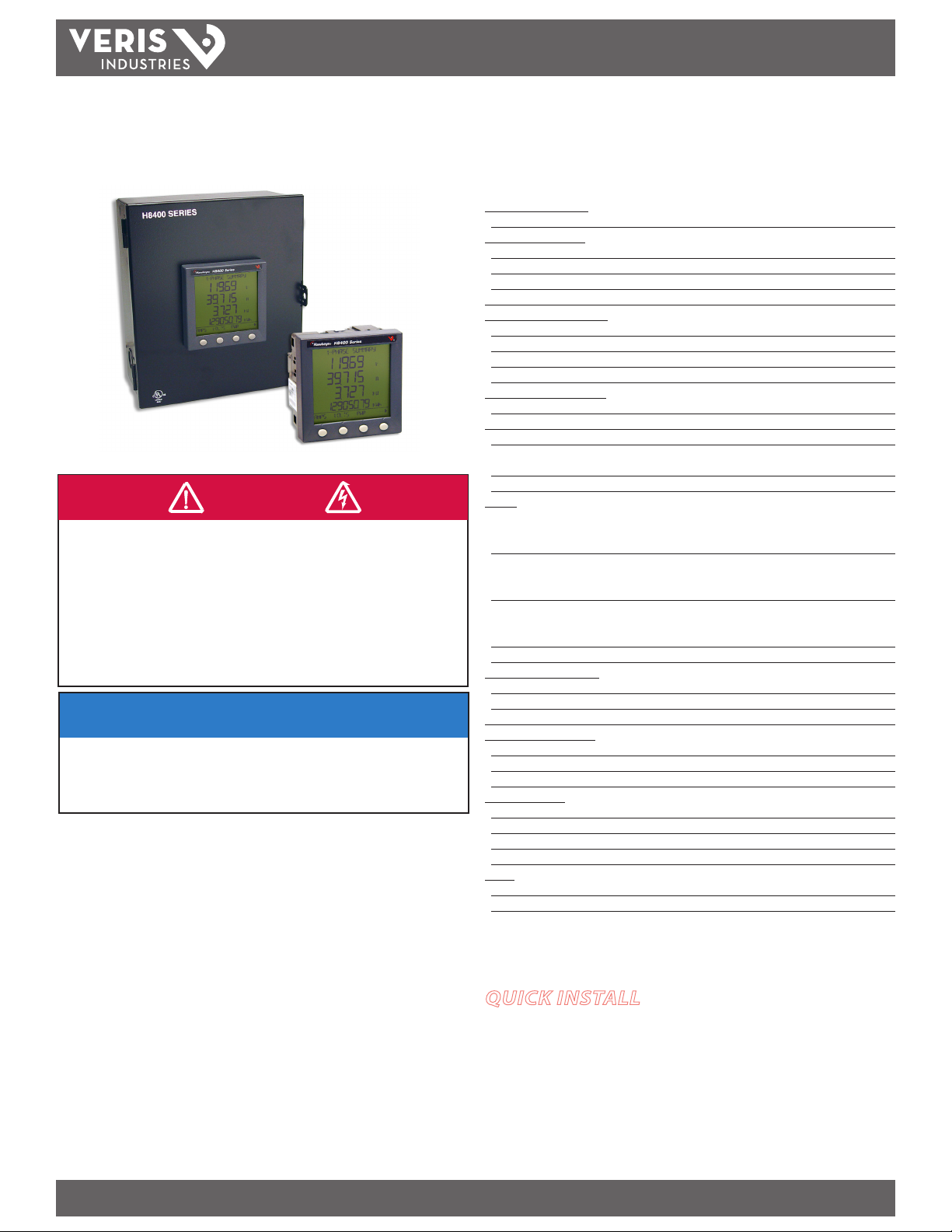
H84xx
Power Meters For Use With 1V CTs
DANGER
HAZARD OF ELECTRIC SHOCK, EXPLOSION, OR ARC FLASH
• Follow safe electrical work practices. See NFPA 70E in the USA, or applicable local codes.
• This equipment must only be installed and serviced by qualified electrical personnel.
• Read, understand and follow the instructions before installing this product.
• Turn off all power supplying equipment before working on or inside the equipment.
• Use a properly rated voltage sensing device to confirm power is off.
DO NOT DEPEND ON THIS PRODUCT FOR VOLTAGE INDICATION
• Only install this product on insulated conductors.
Failure to follow these instructions will result in death or serious injury.
NOTICE
• This product is not intended for life or safety applications.
• Do not install this product in hazardous or classified locations.
• The installer is responsible for conformance to all applicable codes.
• Mount this product inside a suitable fire and electrical enclosure.
FCC PART 15 INFORMATION
NOTE: This equipment has been tested by the manufacturer and found
to comply with the limits for a class A digital device, pursuant to part
15 of the FCC Rules. These limits are designed to provide reasonable
protection against harmful interference when the equipment is
operated in a commercial environment. This equipment generates,
uses, and can radiate radio frequency energy and, if not installed and
used in accordance with the instruction manual, may cause harmful
interference to radio communications. Operation of this equipment in
a residential area is likely to cause harmful interference in which case
INSTALLATION GUIDE
Installer’s Specifications
Electrical Characteristics:
Type of measurement True RMS up to the 15th harmonic. On three-phas e AC system
Measurement A ccuracy:
Current & Voltage ANSI C12.16, 0.5%
Power ANSI C12.16, 1%
Frequency ±-0.01 Hz from 45 to 65 Hz
Data Update Rate 1 sec
Input Voltage Characteristics:
Measured Voltage Max. UL to 600VAC (L-L); CE to 300VAC (L-N)
Metering Over-Range +20%
Impedance 2 MΩ (L-L)/ 1MΩ (L-N)
Frequency Range 45 to 65 Hz
Input Current Characteristics:
CT Scaling Primary: Adjustable from 5A to 32,767A
Measurement Input Range 0 to 1.0VAC (+20% over-range)
Impedance 100 k Ω
Control Power * AC: 100 to 415 ±10%VAC, 5VA; DC: 125 to 250 ±20%VDC, 3W
(see * for 600V option)
Control Power Ride Through Time 100 mS at 120VAC
Output:
Pulse Output #1 H8453V/VB, H84 63V/VB (kWh) N.O., static output
(240 VAC or 300VDC, 100mA max. at 25°C,
derate 0.56mA per °C above 25°C) 2.41kV RMS isolation
Pulse Output #2 H8453V/VB (Phase Detec t or kVARh) N.O., static output
(240 VAC or 300VDC, 100mA max. at 25°C,
derate 0.56mA per °C above 25°C) 2.41kV RMS isolation
Pulse Output #2 H8463V/VB (Phas e Detect or kVARh) N.C., static output
(240VAC or 300VDC, 100mA max. at 25°C,
derate 0.56mA per °C above 25°C) 2.41kV RMS isolation
RS485 Por t; H8436V/VB; H8437V/VB 2-wire, 2400 to 19200 baud, Modbus RTU
Mechanical Characteristics:
Weight H8400V=0.81lb; H8400VB=6.35lb; H8400VBS=9.15lb
IP Degree of Protection (IEC 60529) IP40 front display, meter body IP30 for VB
Display Charac teristics Back-lit green LCD (6 lines total, 4 concurrent values)
Environmental Conditions:
Operating Temperature Meter: 0° to 60 °C; Display: -10° to 50°C
Storage Temperature Meter and Display: -40° to 85°C
Humidity Range 5 to 95% RH at 50°C (non-condensing)
Metering Category:
North America CAT III; for distribu tion systems up to 347V L-N/600VAC L-L
CE CAT III; for distribution systems up to 300V L-N/480VAC L-L
Dielectric Withs tand Per UL 508, EN61010
Conducted and Radiated Emissions FCC part 15 Class B, EN55011
Safety:
North America UL508/C22.2
Europe CE per IEC 61010
*For control voltages >415VAC order H84xxVBS
Modifications to this product without the express authorization of
Veris Industries nullify this statement.
QUICK INSTALL
1. Mount the device in a re/electrical enclosure. Use the retaining clips for the
H84xx-V. Use appropriate wall-mounting screws for the H84xx-VB(S).
2. Wire the device. See the Wiring Diagrams section for options.
3. Congure the communications parameters.
Z204046-0J PAGE 1 ©2011 Veris Industries USA 800.354.8556 or +1.503.598.4564 / support@veris.com 12115
Alta Labs, Enercep t, Enspector, Hawkeye, Trustat, Veris, and the Veris ‘ V’ logo are trademark s or registered tradema rks of Veris Industries, L.L .C. in the USA and /or other count ries.
Page 2
H84xx
TM
INSTALLATION GUIDE
SAFETY
HAZARD OF ELECTRIC SHOCK, EXPLOSION, OR ARC FLASH
• Only qualied electrical workers should install this equipment. Read
entire instructions before performing this work.
• Before performing visual inspections, tests, or maintenance on this
equipment, disconnect all sources of electric power. Assume that all
circuits are live until they have been completely de-energized, tested,
and tagged. Pay particular attention to the design of the power system.
Consider all sources of power, including the possibility of backfeeding.
• Turn o all power supplying the power meter and the equipment in which
it is installed before working on it.
• Always use a properly rated voltage sensing device to conrm that all
power is o.
• Apply appropriate personal protective equipment (PPE) and follow safe
electrical work practices. In the USA, see NFPA 70E.
• Qualied persons performing diagnostics or troubleshooting that require
electrical conductors to be energized must comply with NFPA 70 E Standard for Electrical Safety Requirements for Employee Workplaces and
OSHA Standards - 29 CFR Part 1910 Subpart S - Electrical.
• Before closing all covers and doors, carefully inspect the work area for
tools and objects that may have been left inside the equipment.
• Use caution while removing or installing panels so that they do not
extend into the energized bus; avoid handling the panels, which could
cause personal injury.
• NEVER bypass external fusing.
• NEVER short the secondary of a potential transformer.
• Before performing Dielectric (Hi-Pot) or Megger testing on any
equipment in which the power meter is installed, disconnect all input
and output wires to the power meter. High voltage testing may damage
electronic components contained in the power meter.
• Install the power meter in a suitable electrical and re enclosure.
Failure to follow these instructions may result in death or serious
injury.
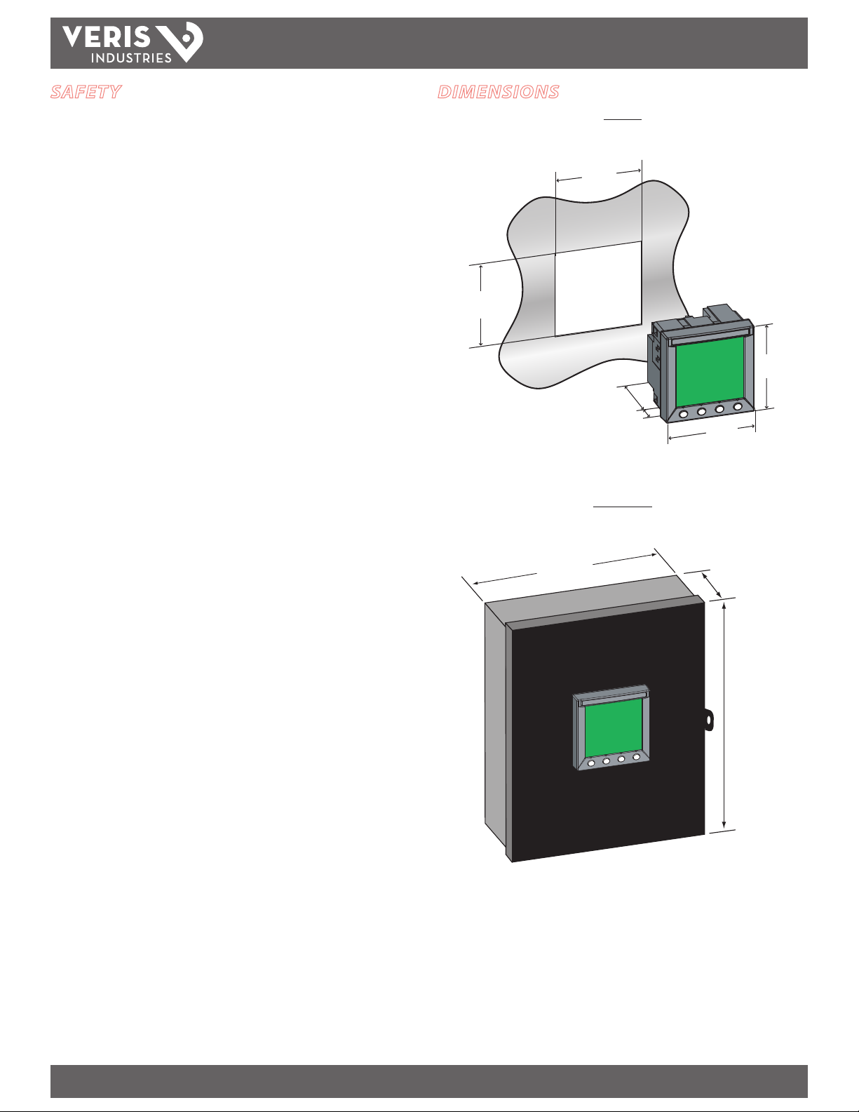
DIMENSIONS
+0.8
3.6"
–0.0
(92 mm)
(210 mm)
H8400 SERIES
8.3"
H84xxV
+0.8
3.6"
–0.0
(92 mm)
2"
(50 mm)
H84xxVB(S)
0.8"
(19 mm)
3.9"
(96 mm)
3.9"
(96 mm)
4.1"
(104 mm)
Always observe all National and Local Codes during installation
of this product.
9.1"
(242 mm)
Mount the box on a solid surface:
1. For use in a pollution degree 2 or better environment only.
2. Connect appropriate safety earth ground wiring to provided grounding terminal.
3. Disconnect devices: in Europe, provide a switch or circuit breaker rated for a
maximum of 20 amps to disconnect the H84xx from the supply source. Place the
switch or circuit breaker in close proximity to the equipment and within easy
reach of the operator, and mark it as the disconnecting device. The disconnecting
device shall meet the relevant requirements of IEC 60947-I and IEC 60947-3 and
be suitable for the application. In the US and Canada, disconnecting fuse holders
can be used.
NOTE: Recommended distance from left sid e of box to another object is 1.8” (45 mm) to allow
meter door to open.
4. Provide overcurrent protection for supply conductors with approved current
limiting devices suitable for protecting the wiring but not exceeding 20 Amps.
5. Wiring can be up to 12 AWG (2mm) and rated min. 600V.
6. After installation, close the box and secure with the provided plastic cable tie or
securing screw. A lockout device may also be used for this purpose.
Z204046-0J PAGE 2 ©2011 Veris Industries USA 800.354.8556 or +1.503.598.4564 / support@veris.com 12115
Alta Labs, Enercep t, Enspector, Hawkeye, Trustat, Veris, and the Veris ‘ V’ logo are trademark s or registered tradema rks of Veris Industries, L.L .C. in the USA and /or other count ries.
Page 3
H84xx
TM
INSTALLATION GUIDE
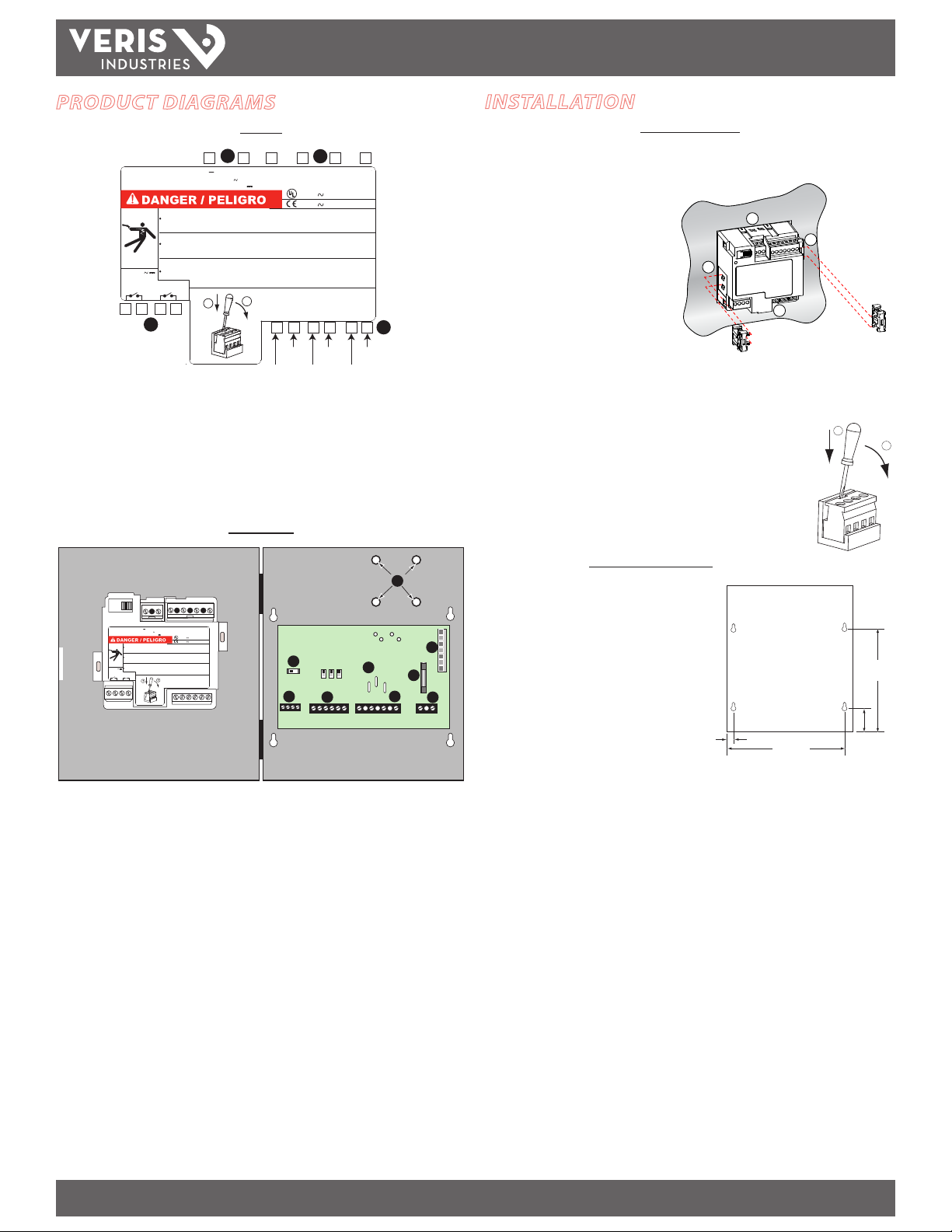
PRODUCT DIAGRAMS
H84xxV
1
1
2 3 4 5 6
+
1 10-415V 5 V A
50/60 Hz / 125-250V 3W
HAZARD OF ELECTRIC SHOCK, EXPLOSION OR ARC FLASH
T urn o f f all power supplying this device and the equipment in which it is installed before
working on it.
Failure to follow these instructions will result in death or serious injur y.
RIESGO DE DESCARG A ELÉCTRICA, EXPLOSIÓN O DESTELLO DE ARCO
Apague la alimentación del dispositivo y del equipo en el que está instalado antes de
efectuar cualquier trabajo.
El incumplimiento de estas precauciones podrá causar la muerte o lesiones serias.
Z104144-0C
RISQUE D'ÉLECTROCUTION, D'EXPLOSION OU D'ARC ELECTRIQUE
Coupez l'alimentation de cet appareil et de l'équipement dans lequel il est installé avant travaille r .
240V
Si ces précautions ne sont pas respectés, cela entraÎnera la mort ou des blessures graves.
100mA max
KWH PHASE or
KVARH
7 8 9 10
1
VO LT AGE INPUTS / ENTRADAS DE TENSIÓ N
ENTRÉES DE TENSION
"CURRENT" INPUTS / ENTRADAS DE CORRIENTE
ENTRÉES DE COURANT 1V NOM. / 1.2V MAX.
2
4
Red
1. Control Power
2. Voltage Inputs
3. 1 Volt ‘‘Current” Inputs
4. Pulse Outputs for H8453V, H8463V or RS-485 Output for H8436V, H8437V
H84xxVB(S)
2
V
V
1
I I
1+ 3+ 2- 2+
14 15 16 17 18 19
White White White
2
600V L-L 50/60Hz
R
480V L-L 50/60Hz
1-
Black
V
3
I I I
Yellow
V
N
I
3-
3
INSTALLATION
H84xxV Mounting
1. Insert the power meter through a 3.6” x 3.6” (92mm x 92mm) cut-out.
2. Attach the two retainer clips to the
power meter using the retainer slots
at position A or position B.
There are two sets of retainer slots
on the left, right, top and bottom of
the power meter. The rst set is for
installation locations thinner than
3 mm (1/8 in.). The second set is for
installation locations 3 to 6 mm (1/8 in.
to 1/4 in.).
NOTE: For use on a at surface of a protective enclosure (for example, in the USA, use
a NEMA Type 1 rated enclosure or better).
Removing the Connectors:
1. Insert the at end of a screwdriver into the groove between the
power meter and the connector, as shown in the image.
2. Pull down the screwdriver to remove the connector.
B
A
A
B
1
2
9
V
V
V
V
2
1
3
+
1 10-415V 5 V A
50/60 Hz / 125-250V 3W
HAZARD OF ELECTRIC SHOCK, EXPLOSION OR ARC FLAS H
T urn o f f all power supplying this device and the equipment in which it is installed before
working on it.
Failure to follow these instructions will result in death or se rious injury .
RIESGO DE DESCARG A ELÉCTRICA, EXPLOSIÓN O DESTELLO DE
Apague la alimentación del dispositivo y del equipo en el que e stá instalado antes de
efectuar cualquier trabajo.
El incumplimiento de estas precauciones podrá causar la muerte o lesiones serias.
Z104389-0A
RISQUE D'ÉLECTROCUTION, D'EXPLOSION OU D'ARC ELECTRIQU E
Coupez l'alimentation de cet appareil et de l'équipement dans l equel il est installé avant travailler .
240V
Si ces précautions ne sont pas respectés, cela entraÎnera la mo rt ou des blessures graves.
100mA max
KWH PHASE o r
KVARH
VO LT AGE INPUTS / ENTRADAS DE TENSIÓN
ENTRÉES DE TENSION
600V L-L 50/60Hz
R
480V L-L 50/60Hz
"CURRENT" INPUTS / ENTRADAS DE CORRIENTE
ENTRÉES DE COURANT 1V NOM. / 1.2V MAX.
I I
1-
1+ 3+ 2- 2+
N
ARC O
I I I
I
3-
1
2
7
J6
J5
J7
A
N
3
8
6
B
4
5
L N
1. RS-485 Terminator Switch (H8436VB/S, H8437VB/S only) *
2. RS-485 Input (H8436VB/S, H8437VB/S) or Pulse Contacts (H8453VB/S, H8463VB/S)
3. 1 Volt “Current” Inputs
4. Voltage Inputs
5. Control Power Input
6. Control Power Fuse — 1/2 Amp, 600VAC
7. Self-Power Connections
H84xxVB(S) Mounting
Mount the meter box at an appropriate
height allowing for easy viewing of the
display.
Allow a clearance of 1.8” (45mm) of open
space on the left side of the meter to allow
the meter door to open.
0.5"
13 mm
7.5"
190 mm
1.5"
38 mm
6.5"
165 mm
8. 600VAC Connections for H84xxVBS or jumper on H84xxVB
9. Studs for 600V transformer — H84xxVBS only
* NOTE: If this unit is the last unit in a daisy chain, the n this switch should be in the “on” position.
Otherwise, this switch should remai n in the “o” position.
Z204046-0J PAGE 3 ©2011 Veris Industries USA 800.354.8556 or +1.503.598.4564 / support@veris.com 12115
Alta Labs, Enercep t, Enspector, Hawkeye, Trustat, Veris, and the Veris ‘ V’ logo are trademark s or registered tradema rks of Veris Industries, L.L .C. in the USA and /or other count ries.
Page 4
TM
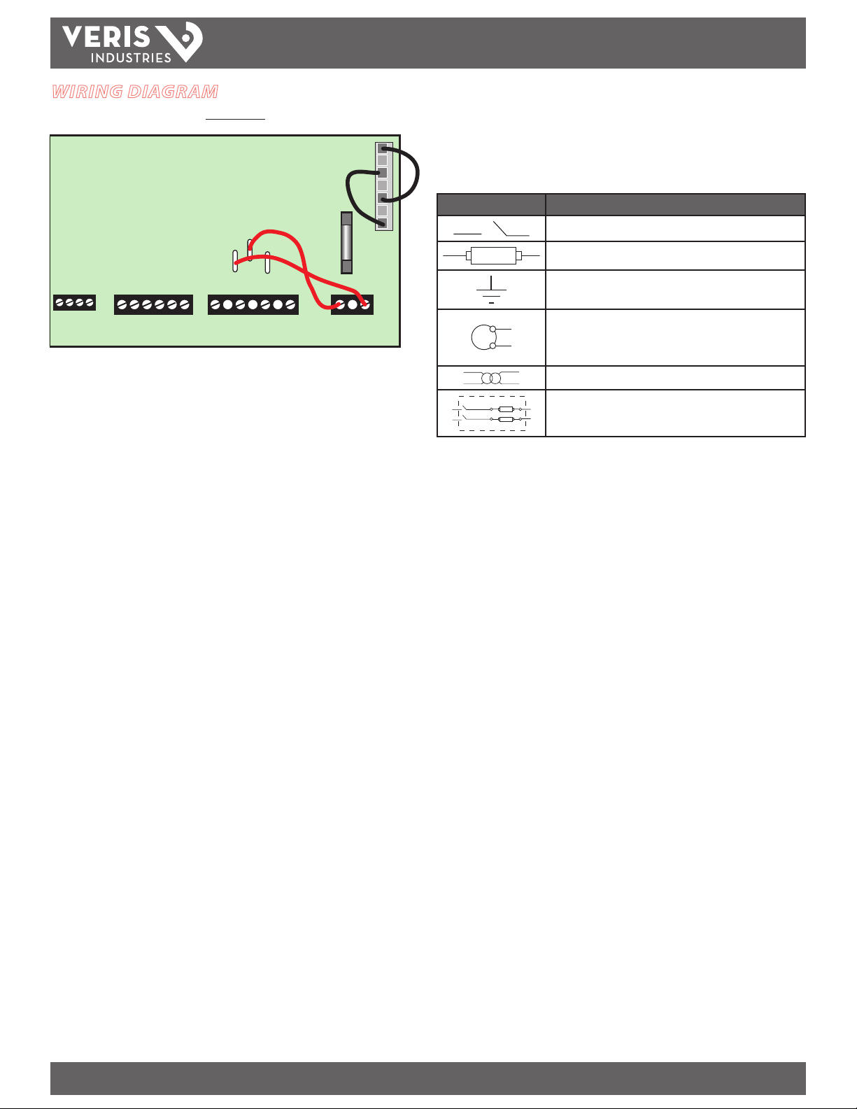
WIRING DIAGRAM
H84xxVB(S)
J6
J5
A
N
H84xx
NOTE: Voltage inputs and control power for distributio n systems up to 347V L-N and 600 V L-L
comply with metering category III. Also, terminal wiring should have a minimum temperature
rating of 80°C.
INSTALLATION GUIDE
The following symbols are used in the diagrams:
Symbol Description
Voltage disconnect switch
J7
B
Fuse
Earth ground
N
L
"CONTROL POWER INPUT"
CONTROL POWER may be taken from the voltage inputs by selecting appropriate
jumper connections.* CONTROL POWER must be below 415V L-L and a maximum of
300V from either line to ground. For operation up to 600VAC, use the X050 DJU 600V
to 300 dropping transformer provided in H84xx-XBS products.
In this product, the jumpers connect to J6 and J8 with 480 or 600V Delta power
systems.
* Set jumpers for N & A . If product will be used on a 480V or higher Delta install ation, provide a
separate control power source or use the optiona l X050 DJU 600V to 300 dropping transformer.
S1
Current transformer
S2
Potential transformer
Protection containing a voltage disconnect switch with a fuse or
disconnect circuit breaker (the protection device must be rated
for the available short-circuit current at the connection point).
Z204046-0J PAGE 4 ©2011 Veris Industries USA 800.354.8556 or +1.503.598.4564 / support@veris.com 12115
Alta Labs, Enercep t, Enspector, Hawkeye, Trustat, Veris, and the Veris ‘ V’ logo are trademark s or registered tradema rks of Veris Industries, L.L .C. in the USA and /or other count ries.
Page 5
H84xx
TM
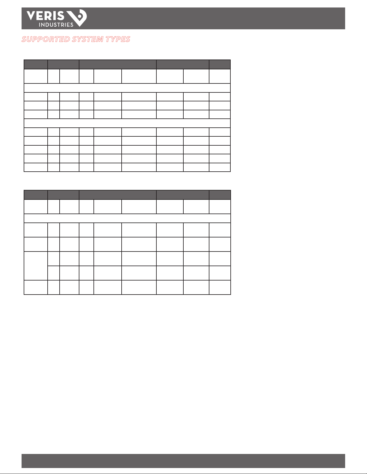
SUPPORTED SYSTEM TYPES
Voltages Less Than or Equal to 347VAC L-N/600VAC L-L, Direct Connect, No PTs
CTs Voltage Connections Meter Configuration
Number of
wires
SIngle-Phase Wiring
2 1 I1 2 V1, Vn L-N 10 No PT 12
2 1 I1 2 V1, V2 L-L 11 No PT 13
3 2 I1, I2 3 V1, V2, Vn L-L with N 12 No PT 14
Three-Phase Wiring
3 3 I1, I2, I3 3 V1, V2, V3 Delta 31 No PT 15
3 1 I1 3 V1, V2, V3 Delta (balanced) 32 No PT 16
4 3 I1, I2, I3 3 V1, V2, V3, Vn 4-Wire Delta 40 No PT 17
4 3 I1, I2, I3 3 V1, V2, V3, Vn Wye 40 No PT 17
4 1 I1 3 V1, V2, V3, Vn Wye (balanced) 44 No PT 23
Voltages Greater Than 347VAC L-N/600VAC L-L
Qty ID Qty ID Type System Type PT Primary
Scale
INSTALLATION GUIDE
Figure
Number
CTs Voltage Connections Meter Configuration
Number of
wires
Three-Phase Wiring
3 3 I1, I2, I3 2 V1, V3 (V2 to
3 1 I1 2 V1, V2, V3 (Vn
4 3 I1, I2, I3 3 V1, V2, V3 (Vn
4 1 I1 3 V1, V2, V3 (Vn
Qty ID Qty ID Type System Type PT Primary
ground)
to ground)
to ground)
3 I1, I2, I3 2 V1, V2, V3 (Vn
to ground)
to ground)
Scale
Delta 31 Based on
Delta (balanced) 32 Based on
Grounded Wye 40 Based on
Wye 42 Based on
Grounded Wye
(balanced)
44 Based on
voltage
voltage
voltage
voltage
voltage
Figure
Number
18
19
20
21
22
Z204046-0J PAGE 5 ©2011 Veris Industries USA 800.354.8556 or +1.503.598.4564 / support@veris.com 12115
Alta Labs, Enercep t, Enspector, Hawkeye, Trustat, Veris, and the Veris ‘ V’ logo are trademark s or registered tradema rks of Veris Industries, L.L .C. in the USA and /or other count ries.
Page 6
TM
L1 L2
N
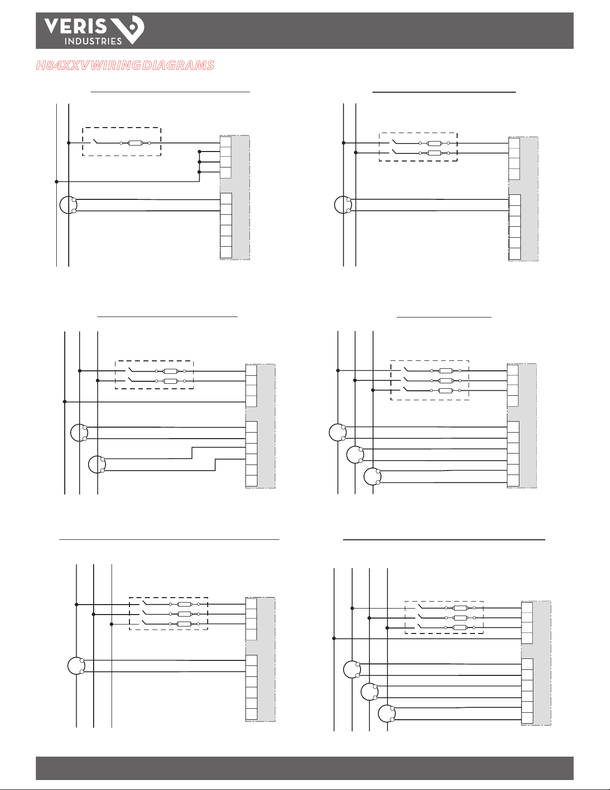
H84X XV WIR ING DIAGR AM S
H84xx
INSTALLATION GUIDE
NL1
1-Phase Line-to-Neutral 2- Wire System 1 CT
USE SYSTEM TYPE 101
S1
S2
1-Phase Direct Voltage Connection 2 CT
USE SYSTEM TYPE 12 USE SYSTEM TYPE 31
14
15
16
17
18
19
1-Phase Line-to-Line 2-Wire System 1 CT
L1 L2
3
V1
4
V2
5
V3
6
VN
I1+
I1–
I2+
S1
S2
I2–
I3+
I3–
USE SYSTEM TYPE 11
3
V1
4
V2
5
V3
6
VN
I1+
14
I1–
15
I2+
16
I2–
17
I3+
18
I3–
19
3-Phase 3-Wire 3 CT no PT
L2 L3L1
3
V1
4
V2
5
V3
6
VN
3
V1
4
V2
5
V3
6
VN
S1
S2
S1
S2
14
15
16
17
18
19
I1+
I1–
I2+
I2–
I3+
I3–
Balanced 3-Phase 3-Wire Direct Voltage Input Connection 1 CT
L2 L3L1
S1
S2
USE SYSTEM TYPE 32
3
4
5
6
14
15
16
17
18
19
V1
V2
V3
VN
I1+
I1–
I2+
I2–
I3+
I3–
S1
S2
S1
S1
S2
S2
14
15
16
17
18
19
I1+
I1–
I2+
I2–
I3+
I3–
3-Phase 4-Wire Wye Direct Voltage Input Connection 3 CT
USE SYSTEM TYPE 40
L2 L3L1N
3
4
5
6
S1
S2
S1
S1
S2
S2
14
15
16
17
18
19
V1
V2
V3
VN
I1+
I1–
I2+
I2–
I3+
I3–
Z204046-0J PAGE 6 ©2011 Veris Industries USA 800.354.8556 or +1.503.598.4564 / support@veris.com 12115
Alta Labs, Enercep t, Enspector, Hawkeye, Trustat, Veris, and the Veris ‘ V’ logo are trademark s or registered tradema rks of Veris Industries, L.L .C. in the USA and /or other count ries.
Page 7
H84xx
TM
INSTALLATION GUIDE
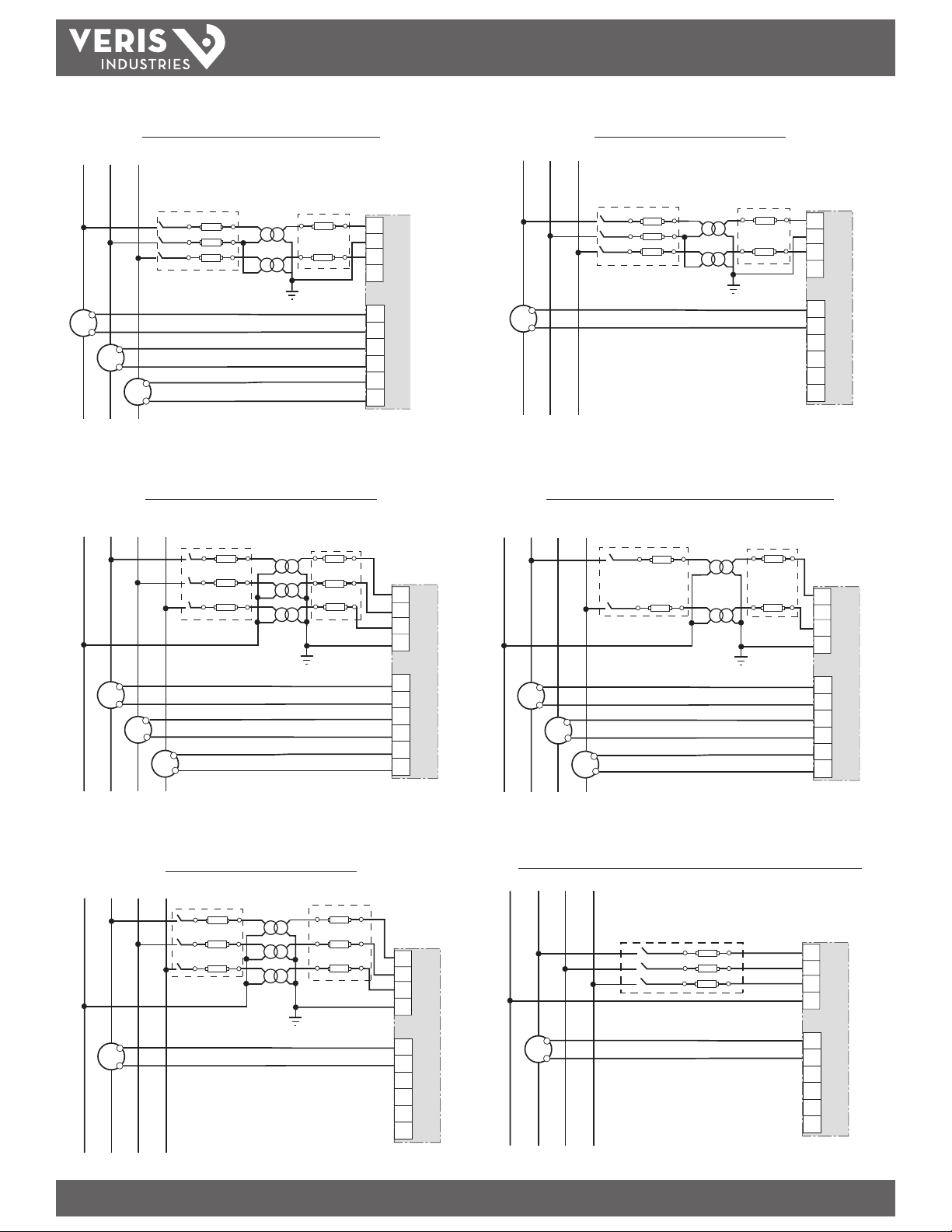
3-Phase 3-Wire Delta Connection 3 CT 2 PT
L2 L3L1
S1
S2
S1
S1
S2
S2
USE SYSTEM TYPE 31
14
15
16
17
18
19
3
V1
4
V2
5
V3
6
VN
I1+
I1–
I2+
I2–
I3+
I3–
3-Phase 4-Wire Wye Connection 3 CT 2 PT
USE SYSTEM TYPE 40
L2 L3L1N
L2 L3L1
S1
S2
3-Phase 4-Wire Wye 3 CT 2PT (for balanced voltage)
Balanced 3-Phase 3-Wire 1 CT 2 PT
USE SYSTEM TYPE 32
USE SYSTEM TYPE 42
L2 L3L1N
3
4
5
6
14
15
16
17
18
19
V1
V2
V3
VN
I1+
I1–
I2+
I2–
I3+
I3–
3
V1
4
V2
5
V3
6
VN
S1
S1
S2
S2
S1
S2
14
15
16
17
18
19
I1+
I1–
I2+
I2–
I3+
I3–
Balanced 3-Phase 4-Wire 3 PT 1 CT
L2 L3L1N
S1
S2
USE SYSTEM TYPE 44
3
4
5
6
14
15
16
17
18
19
V1
V2
V3
VN
I1+
I1–
I2+
I2–
I3+
I3–
S1
S2
S1
S1
S2
S2
Balanced 3-Phase 4-Wire Direct Voltage Input Connection 1 CT
L2 L3L1N
S1
S2
USE SYSTEM TYPE 44
3
4
5
6
14
15
16
17
18
19
3
4
5
6
14
15
16
17
18
19
V1
V2
V3
VN
I1+
I1–
I2+
I2–
I3+
I3–
V1
V2
V3
VN
I1+
I1–
I2+
I2–
I3+
I3–
Z204046-0J PAGE 7 ©2011 Veris Industries USA 800.354.8556 or +1.503.598.4564 / support@veris.com 12115
Alta Labs, Enercep t, Enspector, Hawkeye, Trustat, Veris, and the Veris ‘ V’ logo are trademark s or registered tradema rks of Veris Industries, L.L .C. in the USA and /or other count ries.
Page 8
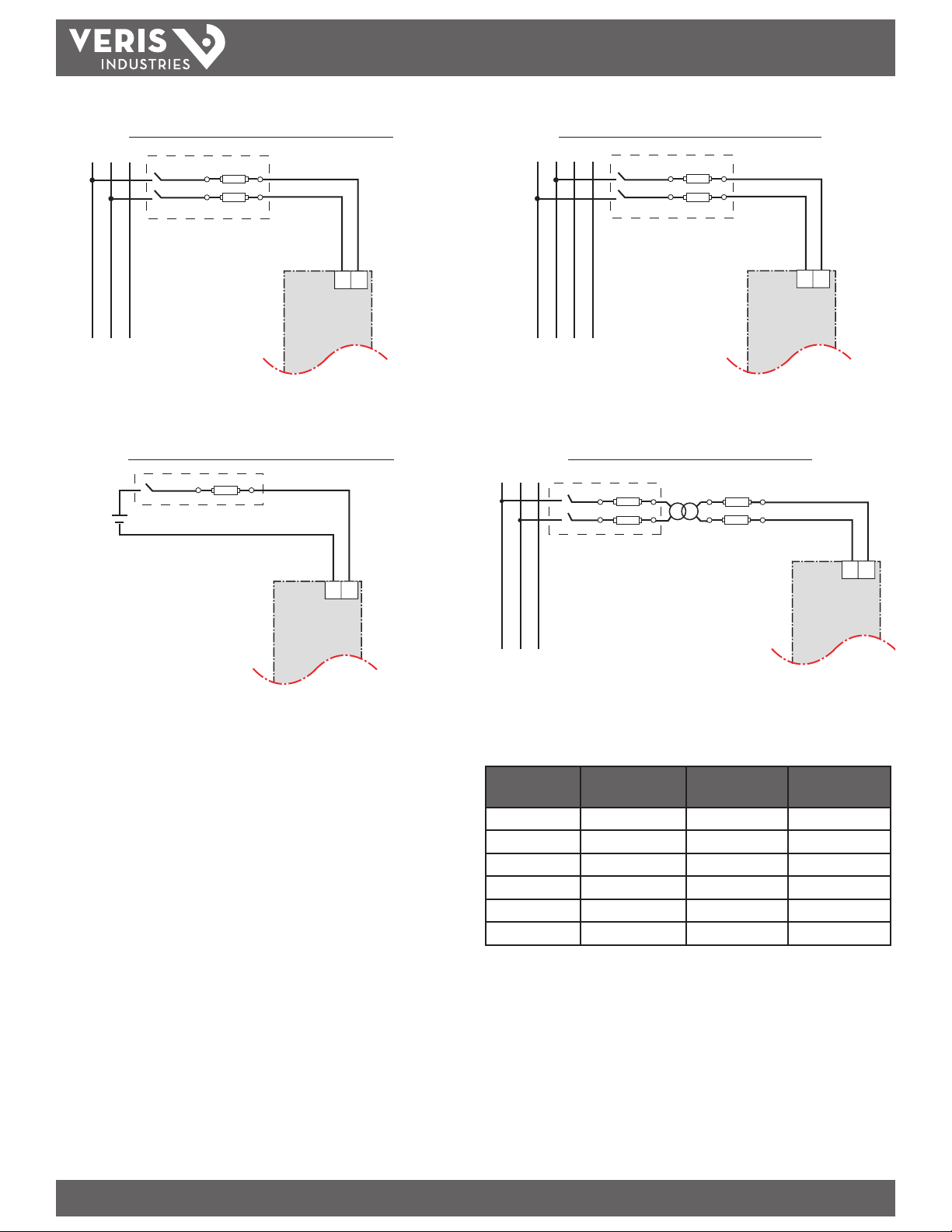
Control Power
H84xx
TM
INSTALLATION GUIDE
Direct Connect Control Power C (Phase to Phase)
L1 L2 L3
• Phase to Phase only when voltage <415 +10%VAC max.
• See Table below.
Direct Connect Control Power (DC Control Power)
12
12
Direct Connect Control Power (Phase to Neutral)
L1 L2 L3N
12
• Phase to Neutral only when voltage <415+10% VAC max.
• See Table below.
Control Power Transformer (CPT) Connection
L1 L2 L3
12
• DC Control Power 100 VDC<V<300VDC
• See Table below.
Fuse Recommendation
1. To avoid distortion, use parallel wires for control power and voltage inputs. Keep
the fuse close to the power source.
2. Use with 480Y/277V and 208Y/120V systems.
3. For an open delta PT connection with 120V L-L secondaries, use system type 31.
• Control Power Transformer 120 or 240VAC. Secondary 50VA max.
• See Table below.
Control Power
Source
CPT Vs < 125V FNM or MDL 250
CPT 125 < Vs < 240V FNQ or FNQ-R 250
CPT 240 < Vs < 305V FNQ or FNQ-R 250
Line Voltage Vs < 240V FNQ-R 250
Line Voltage Vs > 240V FNQ-R 250
DC Vs < 300V LP- CC 500
NOTES:
Place over-current protection as close to the device as possible.
For selecting fuses and circuit breakers other than those listed above, use the following criteria:
• Rate over-current protection as listed above.
• Select current interrupt capacit y based on the installation category and fault current capability.
• Select over-current protection with a time delay.
• Base the voltage rating on the input voltage applied.
• If a 0.25A fuse is not available with the required fault current capability, use a fuse rated at a maximum of 0.5A.
Source Voltage
(V)
Fuse Fuse Amperage
(mA)
Z204046-0J PAGE 8 ©2011 Veris Industries USA 800.354.8556 or +1.503.598.4564 / support@veris.com 12115
Alta Labs, Enercep t, Enspector, Hawkeye, Trustat, Veris, and the Veris ‘ V’ logo are trademark s or registered tradema rks of Veris Industries, L.L .C. in the USA and /or other count ries.
Page 9
H84xx
≤ 100 mA
TM
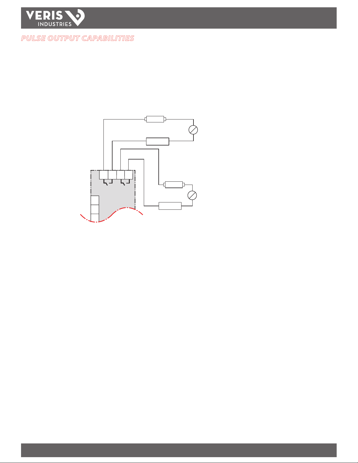
PULSE OUTPUT CAPABILITIES
Solid-state Pulse Output
The H8453 has two normally open solid-state KY outputs. The H8463 has one
normally open KY output and one normally closed KZ solid-state output. One is
dedicated to kWh, and the other is eld-selectable for Phase Detect or kVARh. See the
Setup section for conguration information.
Over-current Protective Device
(not supplied)
Digital Output/Pulse Ou tput is a solid state
pulse output rated for 240VAC/DC max.
Maximum load curren t is 100mA at 25°C.
Derate 0.56mA per °C above 25°C.
LOAD
~
=
INSTALLATION GUIDE
Power So urce
3-240VDC
6-24 0VAC
78910
The over-current protective device
must be rated for the short circuit
current at the connection point.
*The power source should not be a safety e xtra low voltage (SELV) circui t. Pulse outputs are not SELV rated.
V1
3
4
V2
V3
5
kWh OPTION
kVARh
or
PHASE
H8453
(on H8463, the optional output is normally closed)
≤ 100 mA
LOAD
~
=
Power So urce
3-240VDC
6-24 0VAC
Z204046-0J PAGE 9 ©2011 Veris Industries USA 800.354.8556 or +1.503.598.4564 / support@veris.com 12115
Alta Labs, Enercep t, Enspector, Hawkeye, Trustat, Veris, and the Veris ‘ V’ logo are trademark s or registered tradema rks of Veris Industries, L.L .C. in the USA and /or other count ries.
Page 10

H84xx
TM
COMMUNICATIONS
Communications Capabilities
RS-485 Communications Distances:
Baud Rate Maximum Communication Distances
Feet Meters
9600 8000 2438
19200 6000 1829
Note: Use distances as a guide only; they are not guaranteed. Refer to the master
device’s documentation for any additional distance limitations.
Daisy-chaining Devices to the Power Meter
The RS-485 slave port allows the power meter to be connec ted in a daisy chain with
up to 31 2-wire devices.
Belden 1120A or equivalent
INSTALLATION GUIDE
120 Ω terminator on the
last device of the daisy chain*
–
+
Not used
• If the power meter is the rst device on the daisy chain, connect it to the
host device using a RS-232 to RS-485 converter.
• If the power meter is the last device on the daisy chain, terminate it with
the terminator provided.
• The rst device on the chain should also have a 120 Ω terminator between
+ and -.
• The terminal’s voltage and current ratings are compliant with the
requirements of the EIA RS-485 communications standard
* A 120 Ω resistor is included on the circuit board inside the H8436VB/S and H8437VB/S units.
Z204046-0J PAGE 10 ©2011 Veris Industries USA 800.354.8556 or +1.503.598.4564 / support@veris.com 12115
Alta Labs, Enercep t, Enspector, Hawkeye, Trustat, Veris, and the Veris ‘ V’ logo are trademark s or registered tradema rks of Veris Industries, L.L .C. in the USA and /or other count ries.
Page 11

H84xx
TM
OPERATION
Operating the Display
The power meter is equipped with a large, back-lit LCD display. It can display up to
ve lines of information plus a sixth row of menu options.
INSTALLATION GUIDE
AB
L
K
J
Button Symbols
-------
1;
------
C
I
1
2
3
N
1; DMD
View more menu items on the current level.
Return to the previous menu level.
Indicates the menu item is selected and there are no menu levels below
the current level.
Change values or scroll through the available options. When the end of a
range is reached, press + again to return to the rst value or option.
Select the next number of a series.
Move to the next editable eld or save the changes and exit the screen if
the last editable eld is selected.
MAX DEMAND
265
275
268
PHASE
I
Navigation
Change Values
2.4
H
! &
{{{{{}}}}}}
10 50 100
A
{{{{{}}}}}}
10 50 100
A
{{{{{}}}}}}
10 50 100
A
%
A
G
<-
Power Meter Display
A. Type of measurement
B. Screen Title
C. Maintenance icon
D
E
F
D. Bar Chart (%)
E. Units
F. Display more menu items
G. Menu item
H. Selected menu indicator
I. Button
J. Return to previous menu
K. Values
L. Phase
Note: Changes are automatically saved.
Z204046-0J PAG E 11 ©2011 Veris Industries USA 800.354.8556 or +1.503.598.4564 / support@veris.com 12115
Alta Labs, Enercep t, Enspector, Hawkeye, Trustat, Veris, and the Veris ‘ V’ logo are trademark s or registered tradema rks of Veris Industries, L.L .C. in the USA and /or other count ries.
Page 12

H84xx
TM
H84XX DEFAULT SETTINGS
Model H8436X/37x H8453x H8463x
CT Primary Ratio 100A 100A 100A
CT Secondary Ratio 1 V 1 V 1 V
PT Ratio 1:1 (none) 1:1 (none) 1:1 (none)
Frequency 60 Hz 60 Hz 60 Hz
Setup Password 00000 00000 00000
Reset Password 00000 00000 00000
Display Mode IEEE IEEE IEEE
System Type 40 40 40
Modbus Address 001 N/A N/A
Modbus Baud Rate 19200 baud N/A N/A
Modbus Parity None N/A N/A
1st Pulse Contact N/A N.O. N.O.
kWh Pulse Width N/A 100ms 100ms
kWh Pulse Energy Index N/A 1 kWh/Pulse 1 kWh/Pulse
2nd Pulse Contact N/A N.O. N.C.
2nd Pulse Contact Output N/A kVARh Phase Loss
kVARh Pulse Width N/A 100ms 100ms
kVARh Pulse Energy Index N/A 1 kVARh/Pulse 1 kVARh
INSTALLATION GUIDE
Z204046-0J PAGE 12 ©2011 Veris Industries USA 800.354.8556 or +1.503.598.4564 / support@veris.com 12115
Alta Labs, Enercep t, Enspector, Hawkeye, Trustat, Veris, and the Veris ‘ V’ logo are trademark s or registered tradema rks of Veris Industries, L.L .C. in the USA and /or other count ries.
Page 13

TM
SETUP
Set Up the Power Meter
1. Press -----> until you see SETUP.
H84xx
INSTALLATION GUIDE
2. Press SETUP. Enter your password (Default password is 00000).
3. Press + to change a digit, <----- to select the next digit.
4. Press OK.
Set Up CTs
1. Press CT. ----->
2. Enter the PRIM CT (primary CT) number (1 to 32767, using the + and <----but tons).
3. Press OK.
Set Up PTs
1. Press PT. The default is NO PT. Single Phase System types (10, 11, 12) do not allow
PTs.
2. Press +
3. Select the SCALE value: x1, x10, x100, NO PT (for direct connect).
4. Press OK.
5. Enter the PRIM (primary) value.
6. Press OK.
7. Enter the SEC. (secondary) value.
8. Press OK.
Set Up the System Frequency
1. Press -----> until HZ is visible.
2. Press HZ.
3. Press + to select the frequency: 50 Hz or 60 Hz (default is 60Hz).
4. Press OK.
Z204046-0J PAGE 13 ©2011 Veris Industries USA 800.354.8556 or +1.503.598.4564 / support@veris.com 12115
Alta Labs, Enercep t, Enspector, Hawkeye, Trustat, Veris, and the Veris ‘ V’ logo are trademark s or registered tradema rks of Veris Industries, L.L .C. in the USA and /or other count ries.
Page 14

Set Up the Meter System Type
H84xx
TM
INSTALLATION GUIDE
1. Press -----> until SYS is visible.
2. Press SYS.
3. Press + to select the SYS (system type): 10, 11, 12, 30, 31, 32, 40, 42, 44. NOTE: See
Wiring section for a description of the system types.
4. Press OK.
Set Up the Passwords
NOTE: The default passwords are 00000.
1. Press -----> until PASSW (password) is visible.
2. Press PASSW.
3. Press + to change a digit in the SETUP password, <----- to select the next digit.
NOTE: This sets the password to enter the Setup Menu or change SETUP via
Modbus.
3-PHASE SYSTEM
4
3
3
40
1; +OK
<-
PASSWORD SETUP
00000
00000
00000
&
Wire
CT
PT
SYS
&
DIAG.
SETUP
RESET
4. Press OK.
5. Enter the RESET (password to reset the power meter) password. NOTE: This sets
the password required to reset stored values such as kWh via the local RESET
menu or remotely via Modbus (if so equipped.)
6. Press OK to return to the SETUP MODE screen.
Select the Display Operating Mode
1. Press -----> until MODE is visible.
2. Press MODE.
3. Press IEEE or IEC. NOTE: IEEE mode uses W/VA/VAR terminology. IEC mode uses
P/Q /S.
4. Press 1; to return to the SETUP MODE screen.
00000
1; +OK
1; IEEE IEC
<-
SELECT MODE
MIN.MX
Z204046-0J PAGE 14 ©2011 Veris Industries USA 800.354.8556 or +1.503.598.4564 / support@veris.com 12115
Alta Labs, Enercep t, Enspector, Hawkeye, Trustat, Veris, and the Veris ‘ V’ logo are trademark s or registered tradema rks of Veris Industries, L.L .C. in the USA and /or other count ries.
Page 15

H84xx
TM
Set Up Demand
1. Press -----> until DEMND (demand) is visible. (H8437V/ VB/S only)
2. Press DEMND.
3. Enter the MIN (interval in minutes): 0 to 60. Press + to change a digit, <----- to
select the next digit.
4. Press OK. Enter the SUB-I (number of subintervals): 1 to 60. Press + to change a
digit, <----- to select the next digit.
I
INSTALLATION GUIDE
DEMAND SETUP
100
15
1
&
MSEC
MIN
SUB-i
5. Press OK.
NOTE: The calculation method used for SUB-I is as follows:
• 0 = sliding block
• 1 = block
• >1 = rolling block (The SUB-I value must divide evenly into the MIN
value. For example, if MIN is 15, SUB-I can be 3, 5, or 15. If you selected 3,
you would have 3 subintervals at 5 minutes each.)
Set Up Communications (H8436V/VB, H8437V/VB)
1. Press -----> until COM is visible.
2. Press COM.
3. Enter the ADDR (meter address): 1 to 247. Press + to change a digit, <----- to
select the next digit.
4. Press OK.
5. Press + to select the BAUD (baud rate): 2400, 4800, 9600 or 19200.
6. Press OK.
7. Press + to select the parity: EVEN, ODD, NONE.
8. Press OK to return to the SETUP MODE screen.
0.1
1; +OK
<-
COMMS SETUP
001
9600
nOnE
1; +OK
<-
KVARH
ADDR
bauD
Par
mbus
Set Up Pulse Options (H8453V/VB, H8463V/VB)
1. Press -----> until PULSE is visible.
2. Press PULSE.
3. Press + to select the MSEC (kWh pulse duration in milliseconds): 100, 300, 500, or
1000.
4. Press OK.
5. Press + to select the kWh/P (pulse weight): 0.1, 1, 10, 100, 1000, or 10000.
6. Press OK.
0.1
&
MSEC
KWH/P
MSEC
KVARH
7. Select the MSEC (kVARh pulse
duration in milliseconds): PHASE, 100,
300, 500, or 1000.
PULSE SETUP
100
0.1
100
<-
1; +OK
Z204046-0J PAGE 15 ©2011 Veris Industries USA 800.354.8556 or +1.503.598.4564 / support@veris.com 12115
Alta Labs, Enercep t, Enspector, Hawkeye, Trustat, Veris, and the Veris ‘ V’ logo are trademark s or registered tradema rks of Veris Industries, L.L .C. in the USA and /or other count ries.
NOTE: Selecting PHASE changes the output operation from kVARh to PHASE DETECT.
If phase is selected, the H8453V/VB will close the contacts on the PHASE kVARh
output when all three phase voltages are within 25% of each other and no phase
is less than 82.5 volts Line to Neutral. The H8463V/VB will open the contacts on
the Phase kVARh output when all three phase voltages are within 25% of each
other and no phase is less than 82.5 volts line to neutral.
8. Press OK.
9. Select the kVARh (pulse weight):
0.1, 1, 10, 100, 1000, or 10000. This
is unavailable if PHASE is selected
above.
10. Press OK to return to the SETUP
MODE screen.
PULSE SETUP
100
0.1
_ _
<-
1; +OK
&
MSEC
KWH/P
PHASE
Page 16

DIAGNOSTICS
H84xx
TM
INSTALLATION GUIDE
View the Meter Information
1. From the SUMMARY screen, DIAGN (diagnostics)
2. Press METER (meter info).
3. View the meter information (model number, rmware operating system version,
rmware reset system version, and power meter serial number).
Check the Health Status
1. Press HELTH
2. View the health status. If there are no
problems, OK is displayed on the lower
right (see right).
HEALTH STATUS
1; HELTH MAINT
&
OK
METER
^
Reset Energy Accumulators: kWh, kVAh, and kVARh, (Ph, Qh, Sh), (H8453V,
H8463V, H8436V)
1. From the SUMMARY screen, RESET is visible.
2. Press RESET.
3. Enter the RESET password (00000 is the default).
4. Press OK.
5. Press YES to RESET, NO to cancel. The RESET value displayed is a lifetime count of
the number of times the energy accumulators have been reset. This is a security
feature to detect tampering.
Reset Menu, (H8437V) (see below)
1. From the SUMMARY screen, RESET is visible.
METER INFO
H
8400U
10
4
25000193
1; HELTH
The wrench icon is displayed on all
screens when a health problem is
detected (see right). Problems are
shown on the right of the screen with
the location in the center.
Problem:
PLOSS: Phase Loss. F indicates unable to
establish frequency lock on Phase A. In
3 phase systems, A, B, and or C indicates
that the Phase voltage is 25% lower
than the other phases or if the voltage has dropped below 82 volts Line to Neutral.
VCLIP: Voltage Clipping. Indicates the voltage input is too high for the meter to
measure.
ICLIP: Current Clipping. Indicates the current input is too high for the meter to
measure.
&
MODEL
0.5.
R.S.
S.N.
METER
^
2. Press RESET.
3. Enter the RESET password (00000 is the default).
4. Press OK.
5. Press -----> until the parameter you want to reset is displayed.
6. Press the parameter to
cancel.
7. Press YES to reset.
8. Menu Options:
METER - Performs all the resets
below.
ENERG - Resets energy
accumulations (the only reset on the H8436V, H8453V and H8463)
DEMND - Resets Demand calculations and maximum values.
MINMX- All stored minimum and maximum values.
TIMER - Resets usage and elapsed timers.
RESET ENERGY
1
RESET
0.010
No Yes
KWH
Z204046-0J PAGE 16 ©2011 Veris Industries USA 800.354.8556 or +1.503.598.4564 / support@veris.com 12115
Alta Labs, Enercep t, Enspector, Hawkeye, Trustat, Veris, and the Veris ‘ V’ logo are trademark s or registered tradema rks of Veris Industries, L.L .C. in the USA and /or other count ries.
Page 17

H84xx
TM
MENU TREES
Definitions
BDS – Basic Data Stream. Only the Real Energy and Power data points are output.
FDS – Full Data Stream. 26 data points minimum as on the Enercept H8036.
EDS – Extended Data Stream. In addition to the FDS, includes Frequency (phase A),
Current THD, Voltage and THD on each phase.
Syste m Typ es
Support system types 10, 11, 12, 31, 32, 40, 42, & 44.
Modbus Point Map
The Basic Data Stream (BDS) matches the Veris H8035 Enercept meter. The Full Data
Stream (FDS) matches the H8036 Enercept. The Extended Data Stream (EDS) is unique
to the H84xx Series and adds parameters such as Frequency, Demand, and THD. The
conguration of the H84xx is also unique to this device. Integer registers begin at 001
(0x001). Floating point registers begin at 257 (0x101). Conguration registers begin
at 129 (0x081).
H8436/H8453/H8463 FDS Menu Tree (Full Data Stream)
INSTALLATION GUIDE
AMPS VOLTS POWER
I U-V PQS
I
AMPS PER PHASE
---
V VOLTS LINE-LINE
U ---
3-PHASE SUMMARY
--- ---
P
POWER SUMMARY
PQS
V
V L-L V L-N
U V
V VOLTS LINE-NEUT
V ---
P
SUMM PHASE
PQS PHASE
Blue = IEEE
Red = IEC
Black = Same for both IEEE & IEC
P W INSTANT
P
DISPLAY MODE
3-PHASE SUMMARY
ENERG PF
E PF
E ACCUM Wh
----
/ Power Factor
PF
NOTE: Accumulated VAh and
VARh are displayed on Pulse
Models.
Z204046-0J PAGE 17 ©2011 Veris Industries USA 800.354.8556 or +1.503.598.4564 / support@veris.com 12115
Alta Labs, Enercep t, Enspector, Hawkeye, Trustat, Veris, and the Veris ‘ V’ logo are trademark s or registered tradema rks of Veris Industries, L.L .C. in the USA and /or other count ries.
Page 18

TM
H8436/H8453/H8463 FDS Menu Tree (Full Data Stream), continued
3-PHASE SUMMARY
RESET SETUP DIAGN
RESET SETUP DIAGN
R
RESET - PASSWORD
RESET-PASSWORD
21
S
SETUP - PASSWORD
SETUP-PASSWORD
RESET ENERGY?
NO YES
H84xx
H
HELTH METER
MAINT METER
HEALTH STATUS
INSTALLATION GUIDE
METER INFO
S
SETUP MODE
CT PT
CT PT
PT RATIO
CT RATIO
S
SETUP MODE
HZ SYS
F SYS
1/3-PHASE SYSTEM DISPLAY MODE PULSE-SETUP
SYSTEM FREQUENCY
Blue = IEEE
Red = IEC
Black = Same for both IEEE & IEC
S
SETUP MODE
PASSW MODE
PASSW MODE
DISPLAY MODE
PASSWORD SETUP
Optional
S
SETUP MODE
COMMS or PULSE
COMMS or PULSE
or
COMMS SETUP
Optional
Z204046-0J PAGE 18 ©2011 Veris Industries USA 800.354.8556 or +1.503.598.4564 / support@veris.com 12115
Alta Labs, Enercep t, Enspector, Hawkeye, Trustat, Veris, and the Veris ‘ V’ logo are trademark s or registered tradema rks of Veris Industries, L.L .C. in the USA and /or other count ries.
Page 19

TM
H8437 EDS Menu Tree (Enhanced Data Stream)
H84xx
3-PHASE SUMMARY
---
AMPS VOLTS POWER
I U-V PQS
INSTALLATION GUIDE
I
AMPS PER PHASE
---
V
V L-L V L-N
U V
V VOLTS LINE-LINE
U ---
DISPLAY MODE
Blue = IEEE
Red = IEC
Black = Same for both IEEE & IEC
P
SUMM PHASE MINMX
PQS PHASE MINMX
P
POWER SUMMARY
PQS
V VOLTS LINE-NEUT
V ---
P
W VAR VA
P Q S
P
VAR INSTANT
Q
P
W INSTANT
P
P
POWER MIN-MAX
MIN-MAX
P
VA INSTANT
S
Z204046-0J PAGE 19 ©2011 Veris Industries USA 800.354.8556 or +1.503.598.4564 / support@veris.com 12115
Alta Labs, Enercep t, Enspector, Hawkeye, Trustat, Veris, and the Veris ‘ V’ logo are trademark s or registered tradema rks of Veris Industries, L.L .C. in the USA and /or other count ries.
Page 20

TM
H8437 EDS Menu Tree (Enhanced Data Stream), continued
H84xx
3-PHASE SUMMARY
---
ENERG PF HZ
E PF F
INSTALLATION GUIDE
E Wh VARh VAh
Ph Qh Sh
E ACCUM VARh
E ACCUM Wh
F FREQUENCY
----
E ACCUM VAh
/ POWER FACTOR
PF
DISPLAY MODE
Blue = IEEE
Red = IEC
Black = Same for both IEEE & IEC
Z204046-0J PAGE 20 ©2011 Veris Industries USA 800.354.8556 or +1.503.598.4564 / support@veris.com 12115
Alta Labs, Enercep t, Enspector, Hawkeye, Trustat, Veris, and the Veris ‘ V’ logo are trademark s or registered tradema rks of Veris Industries, L.L .C. in the USA and /or other count ries.
Page 21

TM
H8437 EDS Menu Tree (Enhanced Data Stream), continued
H84xx
3-PHASE SUMMARY
---
THD DEMND USAGE
THD DMD USAGE
INSTALLATION GUIDE
T V L-L V L-N I
U V I
T THD I
THD I
T THD V L-N
THD V
T THD V L-L
THD U
DISPLAY MODE
Blue = IEEE
Red = IEC
Black = Same for both IEEE & IEC
U USAGE TOTAL
USAGE TOTAL
U TOTAL TIME
TOTAL TIME
U USAGE TIME
USAGE TIME
D LAST PEAK
LAST PEAK
D PEAK PWR DEMAND
PEAK PQSd
D LAST PWR DEMAND
LAST PQSd
Z204046-0J PAGE 21 ©2011 Veris Industries USA 800.354.8556 or +1.503.598.4564 / support@veris.com 12115
Alta Labs, Enercep t, Enspector, Hawkeye, Trustat, Veris, and the Veris ‘ V’ logo are trademark s or registered tradema rks of Veris Industries, L.L .C. in the USA and /or other count ries.
Page 22

TM
H8437 EDS Menu Tree (Enhanced Data Stream), continued
RESET SETUP DIAGN
RESET SETUP DIAGN
R
RESET - PASSWORD
RESET-PASSWORD
H84xx
3-PHASE SUMMARY
S
SETUP - PASSWORD
SETUP-PASSWORD
INSTALLATION GUIDE
H
HELTH METER
MAINT METER
HEALTH STATUS
METER INFO
S
SETUP MODE
CT PT
CT PT
S
SETUP MODE
HZ SYS
F SYS
PT RATIO 1/3-PHASE SYSTEM DISPLAY MODE PULSE-SETUP
CT RATIO SYSTEM FREQUENCY
R
RESET MODE
METER ENERG
METER E
RESET ALL?
INIT METER ?
RESET ENERGY? RESET TIMER?RESET DEMAND?
R
RESET MODE
DEMND MINMX
DMD MINMX
RESET MIN-MAX?
NO YES
DISPLAY MODE
Blue = IEEE
Red = IEC
Black = Same for both IEEE & IEC
S
SETUP MODE
PASSW MODE
PASSW MODE
PASSWORD SETUP
MINMX
S
SETUP MODE
DEMND COMMS/PULSE
DMD COMMS/PULSE
DEMAND SETUP
PQS DEMAND
R
RESET MODE
TIMER
TIMER
or
COMMS SETUP
Optional
Z204046-0J PAGE 22 ©2011 Veris Industries USA 800.354.8556 or +1.503.598.4564 / support@veris.com 12115
Alta Labs, Enercep t, Enspector, Hawkeye, Trustat, Veris, and the Veris ‘ V’ logo are trademark s or registered tradema rks of Veris Industries, L.L .C. in the USA and /or other count ries.
Page 23

H84xx
TM
INSTALLATION GUIDE
MODBUS POINT MAP
H8400
R/W NV Format Units
REG.
H8436-FDS
H8437-EDS
3-Phase Summary
--- BDS ---
• • 001 R NV
• • 002 R NV kWh E 0-0xFFFF Real Energy Consumption (MSW)
• • 003 R UInt kW W 0-32767 Total Instantaneous Real Power (3 Phase Total)
--- FDS ---
• • 004 R UInt kVA W 0-32767 Total Instantaneous Apparent Power (3 Phase Total)
• • 005 R UInt kVAR W 0-32767 Total Instantaneous Reactive Power (3 Phase Total)
• • 006 R UInt Ratio 0.0001 0-10000 Total Power Factor (Total kW / Total kVA)
• • 007 R UInt Volt V 0-32767 Voltage, L-L, Average of 3 Phases
• • 008 R UInt Volt V 0-32767 Voltage, L-N, Average of 3 Phases
• • 009 R UInt Amp I 0-32767 Current, Average of 3 Phases
Per Phase
• • 010 R UInt kW W 0-32767 Real Power, Phase A
• • 011 R UInt kW W 0-32767 Real Power, Phase B
• • 012 R UInt kW W 0-32767 Real Power, Phase C
• • 013 R UInt Ratio 0.0001 0-10000 Power Factor, Phase A
• • 014 R UInt Ratio 0.0001 0-10000 Power Factor, Phase B
• • 015 R UInt Ratio 0.0001 0-10000 Power Factor, Phase C
• • 016 R UInt Volt V 0-32767 Voltage, Phase A-B
• • 017 R UInt Volt V 0-32767 Voltage, Phase B-C
• • 018 R UInt Volt V 0-32767 Voltage, Phase A-C
• • 019 R UInt Volt V 0-32767 Voltage, Phase A-N
• • 020 R UInt Volt V 0-32767 Voltage, Phase B-N
• • 021 R UInt Volt V 0-32767 Voltage, Phase C-N
• • 022 R UInt Amp I 0-32767 Current, Instantaneous, Phase A
• • 023 R UInt Amp I 0-32767 Current, Instantaneous, Phase B
• • 024 R UInt Amp I 0-32767 Current, Instantaneous, Phase C
--- EDS ---
• 025 R UInt Amp I 0-32767 Current, Instantaneous, Neutral
• 026 R UInt Hz 0.01 4500-6500 Frequency (derived from Phase A)
• 027 R NV UInt kW W 0-32767 Total Real, Power Minimum
• 028 R NV UInt kW W 0-32767 Total Real, Power Maximum
Accumulated Energy
• 029 R NV
• 030 R NV KVAh E 0-0xFFFF Apparent Energy Consumption (MSW)
• 031 R NV
• 032 R NV KVARh E 0-0xFFFF Reactive Energy Consumption (MSW)
Per Phase Power
• 033 R UInt k VA W 0-32767 Apparent Power, Phase A
• 034 R UInt k VA W 0-32767 Apparent Power, Phase B
• 035 R UInt k VA W 0-32767 Apparent Power, Phase C
• 036 R UInt kVAR W 0-32767 Reactive Power, Phase A
• 037 R UInt kVAR W 0-32767 Reactive Power, Phase B
• 038 R UInt kVAR W 0-32767 Reactive Power, Phase C
ULong
ULong
ULong
kWh E 0-0xFFFF Real Energy Consumption (LSW)
KVA h E 0-0xFFFF Apparent Energy Consumption (LSW)
KVA Rh E 0-0xFFFF Reactive Energy Consumption (LSW)
Scale
Factor/
Mult.
Range Description
Integer Statistics
Z204046-0J PAGE 23 ©2011 Veris Industries USA 800.354.8556 or +1.503.598.4564 / support@veris.com 12115
Alta Labs, Enercep t, Enspector, Hawkeye, Trustat, Veris, and the Veris ‘ V’ logo are trademark s or registered tradema rks of Veris Industries, L.L .C. in the USA and /or other count ries.
Page 24

H84xx
TM
INSTALLATION GUIDE
H8400
R/W NV Format Units
REG.
H8436-FDS
H8437-EDS
Demand
• 039 R UInt kW W 0-32767 Total Real Power Present Demand
• 040 R UInt k VA W 0-32767 Total Apparent Power Present Demand
• 041 R UInt kVAR W 0-32767 Total Reactive Power Present Demand
• 042 R NV UInt kW W 0-32767 Total Real Power Max Demand
• 043 R NV UInt kVA W 0-32767 Total Apparent Power Max Demand
• 044 R NV UInt kVAR W 0-32767 Total Reactive Power Max Demand
Usage Time
• 045 R NV UInt Hours 1 0-32767 Usage Hours
• 046 R NV UInt Minutes 1 0-59 Usage Minutes
• 047 R NV UInt Hours 1 0-32767 Total Hours
• 048 R NV UInt Minutes 1 0-59 Total Minutes
• 049 R NV UInt % .01 0-10000 Percent Usage Percent Usage = Usage Time / Total Time .
THD
• 050 R UInt % 0.1 0-10000 THD, Voltage A-N
• 051 R UInt % 0.1 0-10000 THD, Voltage B-N
• 052 R UInt % 0.1 0-10000 THD, Voltage C-N
• 053 R UInt % 0.1 0-10000 THD, Voltage A-B
• 054 R UInt % 0.1 0-10000 THD, Voltage B-C
• 055 R UInt % 0.1 0-10000 THD, Voltage A-C
• 056 R UInt % 0.1 0-10000 THD, Current Phase A
• 057 R UInt % 0.1 0-10000 THD, Current, Phase B
• 058 R UInt % 0.1 0-10000 THD, Current, Phase C
Conguration
--- BDS ---
--- FDS ---
• • 129 R/W UInt N/A
• • 130 R/W UInt
• • 131 R/W UInt 1-32767 CT Ratio – Primary
5A 5A 132 R/W UInt 1 or 5 A CT Ratio – Secondary (H8400A Only, unused on H8400V)
• • 133 R/W UInt 1-32767 PT Ratio – Primary
• • 134 R/W UInt 0,1,10,100 PT Ratio – Scale (0 = No PT)
• • 135 R/W UInt 100,110,115, 120 PT Ratio – Secondary
• • 136 R/W UInt Hz 50 or 60
• • 137 R/W UInt 0.1
Scale
Factor/
Mult.
Range Description
This combination timer counts the total time for
which the absolute current on at least one phase
is >0.1 Amp.
This timer counts the total time since the usage
timer was reset.
Reset:
- Write 30078 to clear all Energy Accumulators to 0 (All).
- Write 14255 to reset all Power Min/Max to Present Values
(H8400 EDS Only).
- Write 21212 to reset Peak Demand values to Present Demand Values
(H8400 EDS Only).
- Write 10001 to clear the Usage Timers to 0 (H8400 EDS Only).
- Read always returns 0.
10,11,12,30,31,
32,40,42,44
System Type
Current Inputs
Voltage Inputs
Z204046-0J PAGE 24 ©2011 Veris Industries USA 800.354.8556 or +1.503.598.4564 / support@veris.com 12115
Alta Labs, Enercep t, Enspector, Hawkeye, Trustat, Veris, and the Veris ‘ V’ logo are trademark s or registered tradema rks of Veris Industries, L.L .C. in the USA and /or other count ries.
Page 25

H84xx
TM
INSTALLATION GUIDE
H8400
R/W NV Format Units
REG.
H8436-FDS
H8437-EDS
• • 138 R/W SInt
• • 139 R/W SInt Scale Factor V (voltage) Default = -1
• • 140 R/W SInt Scale Factor W (power) Default = -2
• • 141 R/W SInt Scale Factor E (energy) Default = -2
• • 142 R UInt Reserved, always returns 0
• • 143 R UInt Reserved, always returns 0
• • 144 R UInt Reserved, always returns 0
• • 145 R UInt Reserved, always returns 0
• • 146 R UInt
• • 147 R NV UInt 0-32767 Count of Energy Accumulator resets
--- EDS ---
• 148 R NV UInt 0-32767 Count of Usage Timer resets
• 149 R/W NV UInt Minutes 1-60
• 150 R/W NV UInt 0-60
3-Phase Summary
--- BDS ---
• • 257/258 R NV Float kWh Real Energy Consumption
• • 259/260 R Float kW Total Instantaneous Real Power
--- FDS ---
• • 261/262 R Float kVA Total Instantaneous Apparent Power
• • 263/264 R Float kVAR Total Instantaneous Reactive Power
• • 265/266 R Float Ratio 0.0-1.0 Total Power Factor (Total KW / Total KVA)
• • 267/268 R Float Volt Voltage, L-L, Average of 3 Phases
• • 269/270 R Float Volt Voltage, L-N, Average of 3 Phases
• • 271/272 R Float Amp Current, Average of 3 Phases
Scale
Factor/
Mult.
-4 0.0001
-3 0.001
-2 0.01
-1 0.1
0 1.0
1 10.0
2 100.0
3 1000.0
4 10000.0
Range Description
Scale Factor I (current) Default = -2
Error Bitmap:
bit0: Phase A Voltage out of range
bit1: Phase B Voltage out of range
bit2: Phase C Voltage out of range
bit3: Phase A Current out of range
bit4: Phase B Current out of range
bit5: Phase C Current out of range
bit6: Frequency out of range or insucient voltage on Phase A to determine frequency.
*range of 45-65 Hz.
bit7: Reserved for future use
bit8: Phase Loss A
bit9: Phase Loss B
bit10: Phase Loss C
bit11-15: Reserved for future use
(Power) Demand Block Interval – Used for PQS (P=Real Power KW, Q=Reactive Power KVAR,
and S=Apparent Power KVA) demand calculations.
Number of Power Demand Block Sub-Intervals - Sets the number of sub-intervals per
Demand Block Interval (above). The method of demand calculation is set as follows:
0 = Sliding Block. Like rolling block, but with a subinterval of 15 seconds is used for Demand
Intervals <= 15 minutes, or 60 seconds for intervals > 15 minutes.
1 = Block. Fixed block with no sub-intervals.
>1 = Rolling Block. The number of sub-intervals per block. This value must divide evenly
into the Block Demand Interval (above). For example, if the Demand Block Interval is 15
minutes, valid Sub-Interval values are: 3, 5, or 15. If the value of 3 is chosen, then there will
be 3 subintervals of 5 minutes each.
Floating Point Statistics
Note: These registers
contain a signed
integer, which
scales the
corresponding
parameters.
Z204046-0J PAGE 25 ©2011 Veris Industries USA 800.354.8556 or +1.503.598.4564 / support@veris.com 12115
Alta Labs, Enercep t, Enspector, Hawkeye, Trustat, Veris, and the Veris ‘ V’ logo are trademark s or registered tradema rks of Veris Industries, L.L .C. in the USA and /or other count ries.
Page 26
H84xx
TM
INSTALLATION GUIDE
H8400
R/W NV Format Units
REG.
H8436-FDS
H8437-EDS
Per Phase
• • 273/274 R Float kW Real Power, Phase A
• • 275/276 R Float kW Real Power, Phase B
• • 277/278 R Float kW Real Power, Phase C
• • 279/280 R Float Ratio 0.0-1.0 Power Factor, Phase A
• • 281/282 R Float Ratio 0.0-1.0 Power Factor, Phase B
• • 283/284 R Float Ratio 0.0-1.0 Power Factor, Phase C
• • 285/286 R Float Volt Voltage, Phase A-B
• • 287/288 R Float Volt Voltage, Phase B-C
• • 289/290 R Float Volt Voltage, Phase A-C
• • 291/292 R Float Volt Voltage, Phase A-N
• • 293/294 R Float Volt Voltage, Phase B-N
• • 295/296 R Float Volt Voltage, Phase C-N
• • 297/298 R Float Amp Current, Instantaneous, Phase A
• • 299/300 R Float Amp Current, Instantaneous, Phase B
• • 301/302 R Float Amp Current, Instantaneous, Phase C
--- EDS ---
• 303/304 R Float Amp Current, Instantaneous, Neutral
• 305/306 R Float Hz 45.0-65.0 Frequency (derived from Phase A)
• 307/308 R NV Float kW Total Real Power Minimum
• 309/310 R NV Float kW Total Real Power Maximum
• 311/312 R NV Float kVA h Apparent Energy Consumption
• 313/314 R NV Float kVARh Reactive Energy Consumption
Per Phase Power
• 315/316 R Float kVA Apparent Power, Phase A
• 317/318 R Float kVA Apparent Power, Phase B
• 319/320 R Float kVA Apparent Power, Phase C
• 321/322 R Float kVAR Reactive Power, Phase A
• 323/324 R Float kVAR Reactive Power, Phase B
• 325/326 R Float kVAR Reactive Power, Phase C
Demand
• 327/328 R Float kW Total Real Power Present Demand
• 329/330 R Float kVA Total Apparent Power Present Demand
• 331/332 R Float kVAR Total Reactive Power Present Demand
• 333/334 R NV Float kW Total Real Power Max Demand
• 335/336 R NV Float kVA Total Apparent Power Max Demand
• 337/338 R NV Float kVAR Total Reactive Power Max Demand
Usage Time
• 339/340 R NV Float Hours >= 0.0 Usage Hours
• 341/342 R NV Float Minutes 0.0-59.0 Usage Minutes
• 343/344 R NV Float Hours >= 0.0 Total Hours
• 345/346 R NV Float Minutes 0.0-59.0 Total Minutes
Scale
Factor/
Mult.
Range Description
This combination
timer counts the
total time for
which the absolute
current on at least
one phase is >0.1
Amp.
This timer counts the
total time since the
usage timer was
reset.
• 347/348 R NV Float % 0.0-100.0 Percent Usage
Percent Usage =
Usage Time / Total
Time.
Z204046-0J PAGE 26 ©2011 Veris Industries USA 800.354.8556 or +1.503.598.4564 / support@veris.com 12115
Alta Labs, Enercep t, Enspector, Hawkeye, Trustat, Veris, and the Veris ‘ V’ logo are trademark s or registered tradema rks of Veris Industries, L.L .C. in the USA and /or other count ries.
Page 27

H84xx
TM
INSTALLATION GUIDE
H8400
H8436-FDS
H8437-EDS
REG.
R/W NV Format Units
Scale
Factor/
Mult.
Range Description
THD
• 349/350 R Float % 0.0-1000.0 THD, Voltage A-N
• 351/352 R Float % 0.0-1000.0 THD, Voltage B-N
• 353/354 R Float % 0.0-1000.0 THD, Voltage C-N
• 355/356 R Float % 0.0-1000.0 THD, Voltage A-B
• 357/358 R Float % 0.0-1000.0 THD, Voltage B-C
• 359/360 R Float % 0.0-1000.0 THD, Voltage A-C
• 361/362 R Float % 0.0-1000.0 THD, Current, Phase A
• 363/364 R Float % 0.0-1000.0 THD, Current, Phase B
• 365/366 R Float % 0.0-1000.0 THD, Current, Phase C
Modbus Conguration (Downloadable rmware support only)
• • 7000 R NV UInt 0-32767 Firmware Version, Reset System (Boot Down Loader)
• • 7001 R NV UInt Firmware Version, Operating System (Application)
• • 7002/03 R NV ULong Serial Number (date/time of manufacture in UTC)
• • 7004 R NV UInt 15166 Device ID
• • 7005 R NV UInt 1-247 Modbus Address
• • 7006 R NV UInt
2400,4800,
9600,19200
Baud rate
• • 7007 R NV UInt Password (always returns 0). Used only for download.
• • 7008 R UInt Self test (always returns 0)
• • 7009 R UInt 0,65535
PLOS. Returns the one’s complement of software’s safe vectors ag. Indicates if the
Application (OS) or Boot (Downloader/Reset System) is running.
• • 7010 R UInt Reserved, always returns 0
• • 7011 R UInt Reserved, always returns 0
• • 7012 R UInt Reserved, always returns 0
• • 7013 R UInt Reserved, always returns 0
• • 7014 R UInt Reserved, always returns 0
Command Interface (Downloadable rmware support only)
• • 7015 R/W UInt Command
• • 7016-031 R/W UInt Parameters
• • 7032 R/W UInt Status
• • 7033 R/W UInt Result
• • 7034 R/W UInt I/O Data
• • 7035-162 R/W UInt Data Area
Note 1: Calculate demand using sliding, xed, or rolling block intervals. See registers 4117-4119 for settings.
Note 2: DOWNLOADABLE FIRMWARE. When the Operating System is erased, only registers 7000-7162 are available. Register 7001 (Firmware Version, Operating System) reads
as 0 in this condition. Additionally, the ID string returned from a “Report ID” query (0x11) will be “Veris Power Meter - RESET SYSTEM RUNNING”.
Note 3: THD (Total Harmonic Distortion) is calculated as the % ratio over the fundamental frequency. H
2
2
2
√ H
+ H
+ H
2
3
2
+ H
+ ... to the 15th harmonic
4
5
H
1
is the nth harmonic.
n
Note 4: Unused or unsupported Integers return 0x8000, Floats 0x7FC00000
Z204046-0J PAGE 27 ©2011 Veris Industries USA 800.354.8556 or +1.503.598.4564 / support@veris.com 12115
Alta Labs, Enercep t, Enspector, Hawkeye, Trustat, Veris, and the Veris ‘ V’ logo are trademark s or registered tradema rks of Veris Industries, L.L .C. in the USA and /or other count ries.
Page 28

H84xx
TM
Legend
R/W: R=Read only, R/W=Read/Write
NV: Value is stored in non-volatile memory
Format
UInt: Unsiged 16-bit integer, read most signicant Byte (MSB) rst.
SInt: Signed 16-bit integer, read most signicant Byte (MSB) rst.
ULong: Unsigned 32-bit integer; Upper 16-bits Most Signicant Word (MSW), in
lowest numbered register (257/258)=MSW/LSW)
Float: 32-bit oating point; encoded per IEEE Standard 754 single precision; Upper
16-bits Most Signicant Word (MSW) in lowest numbered register (257/258)=MSW/
LSW)
Scale Factor/Multiplier
Integer Registers must be multiplied by this value to be read correctly in the given
units. Scale Factors I, V, W, and E are congurable (see registers 138-141).
Defaults are: I = 0.01, V = 0.1, W = 0.01, E = 0.01
Modbus Commands Supported
DATA OUTPUTS
Full Data Set (FDS)
kWh, Consumption
kW, Real Power
kVAR, Reactive power
kVA, Apparent power
Power fac tor
Voltage, line to line
Voltage, line to neutral
Amps, Average current
kW, Real power ØA
kW, Real power ØB
kW, Real power ØC
Power factor ØA
Power factor ØB
Power factor ØC
Voltage, ØA to ØB
Voltage, ØB to ØC
Voltage, ØA to ØC
Voltage, ØA to Neutral
Voltage, ØB to Neutral
Voltage, ØC to Neutral
Amps, Current ØA
Amps, Current ØB
Amps, Current ØC
INSTALLATION GUIDE
Extended Data Set (EDS), Full Data Set (FDS)
Amps, Current Neutral
Frequency
kVAh, Consumption
kVARh, Consumption
Minimum Real power
Maximum Real power
KVA, Apparent Power, Per Phase
KVAR, Reactive Power, Per Phase
KW, Total Real Power Present Demand
KVA, Total Apparent Power Present Demand
KVAR, Total Reactive Power Present Demand
KW, Total Real Power Max Demand
KVA, Total Apparent Power Max Demand
KVAR, Total Reactive Power Max Demand
THD, Voltage A-N, B-N, C-N
THD, Voltage A-B, B-C, A-C
THD, Current, Per Phase
Usage Hours
Usage Minutes
Total Hou rs
Total Minutes
0X03: Read holding registers
0x04: Read input registers
0x06: Preset single register
0x10: Preset multiple registers
0x11: Report ID
Return string:
byte0: address
by te1: 0x 11
byte2: #bytes following w/out crc
byte3: ID byte = 250
bytes4: status = 0xFF
bytes5+: ID string = “H84__ Power Meter”
last 2 bytes: CRC
0x2B: Read Device Identication, BASIC implementation (0x00, 0x01 and 0x02 data),
Conformity Level 1.
Object Values:
0x01: Vendor Name = “Veris Industries”
0x02: Product Code = “H84__”
0x03: Major/Minor Revision = “Vxx.yyy”, where xx.yyy is the OS version
number (reformatted version of the Modbus register #7001, (Firm
ware Version, Operating System). If register #7001 == 12345, then
the 0x03 data would be “V12.345”).
When the Operating System is erased, only registers 7000-7162 are available. Register 7001 (Firmware Version, Operating System) will read as 0 in this condition.
Z204046-0J PAGE 28 ©2011 Veris Industries USA 800.354.8556 or +1.503.598.4564 / support@veris.com 12115
Alta Labs, Enercep t, Enspector, Hawkeye, Trustat, Veris, and the Veris ‘ V’ logo are trademark s or registered tradema rks of Veris Industries, L.L .C. in the USA and /or other count ries.
Page 29

H84xx
TM
INSTALLATION GUIDE
TROUBLESHOOTING
Problem Cause Solution
The maintenance wrench icon
appears in the power meter
display.
The display is blank after applying
control power to the meter.
The data displayed is inaccurate. Incorrect setup values Verify the values entered for power meter setup
Cannot communicate with power
meter from a remote personal
computer.
There is a problem with the inputs to the power meter. Go to DIAGN>HELTH (MAINT). The error messages
describe the problem. See the Diagnostics section
(page 16) for details.
The meter is not receiving adequate power. Verify that the meter control power (terminals 1 and 2)
are receiving the necessary voltage. See the Control
Power wiring diagram (page 9).
Verify that the LED is blinking.
Check the fuse.
parameters (CT and PT ratings, system type, nominal
frequency, etc.). See the Setup section (page 13).
Incorrect voltage inputs Check power meter voltage input terminals to verify
adequate voltage.
Power meter is wired improperly. Check all CTs and PTs to verify correct connection to the
same service, PT polarity, and adequate powering.
Check shorting terminals, if used. See the Wiring
Diagrams (pages 6-8) section for more information.
Power meter address is incorrect. Verify that the meter is correctly addressed (see Setup
section).
Power meter baud rate is incorrect. Verify that the baud rate of the meter matches that of
all other devices on its communications link (see Setup
section).
Communications lines are improperly connected. Verify the power meter communications connections
(see the Communications section).
Verify the terminating resistors are properly installed on
both ends of a chain of units. Units in the middle of a
chain should not have a terminator.
Z204046-0J PAGE 29 ©2011 Veris Industries USA 800.354.8556 or +1.503.598.4564 / support@veris.com 12115
Alta Labs, Enercep t, Enspector, Hawkeye, Trustat, Veris, and the Veris ‘ V’ logo are trademark s or registered tradema rks of Veris Industries, L.L .C. in the USA and /or other count ries.
 Loading...