

Page 1
Installation Guide
the user will be required to correct the interference at his own expense.
Power Monitoring
AH06 (optional mounting
bracket for small, medium,
and large CTs)
DANGER
HAZARD OF ELECTRIC SHOCK, EXPLOSION, OR ARC FLASH
• Follow safe electrical work practices. See NFPA 70E in the USA, or applicable local codes.
• This equipment must only be installed and serviced by qualified electrical personnel.
• Read, understand and follow the instructions before installing this product.
• Turn off all power supplying equipment before working on or inside the equipment.
• Use a properly rated voltage sensing device to confirm power is off.
DO NOT DEPEND ON THIS PRODUCT FOR VOLTAGE INDICATION
• Only install this product on insulated conductors.
Failure to follow these instructions will result in death or serious injury.
A qualied person is one who has skills and knowledge related to the construction and
operation of this electrical equipment and the installation, and has received safety
training to recognize and avoid the hazards involved. NEC2011 Article 100
No responsibility is assumed by Veris Industries for any consequences arising out of the
use of this material.
NOTICE
• This product is not intended for life or safety applications.
• Do not install this product in hazardous or classified locations.
• The installer is responsible for conformance to all applicable codes.
• Mount this product inside a suitable fire and electrical enclosure.
FCC PART 15 INFORMATION
NOTE: This equipment has been tested by the manufacturer and found
to comply with the limits for a class A digital device, pursuant to part
15 of the FCC Rules. These limits are designed to provide reasonable
protection against harmful interference when the equipment is
operated in a commercial environment. This equipment generates,
uses, and can radiate radio frequency energy and, if not installed and
used in accordance with the instruction manual, may cause harmful
interference to radio communications. Operation of this equipment in
a residential area is likely to cause harmful interference in which case
Modifications to this product without the express authorization of
Veris Industries nullify this statement.
Always observe all National and Local Codes during installation of this
product.
Provide a disconnect device to disconnect the H81xx from the supply source.
Place this device in close proximity to the equipment and within easy reach of
the operator, and mark it as the disconnecting device. The disconnecting device
shall meet the relevant requirements of IEC 60947-I and IEC 60947-3 and be
suitable for the application. In the US and Canada, disconnecting fuse holders
can be used.
Provide overcurrent protection devices for supply conductors. Install per
national or local regulations.
If the equipment is used in a manner not specied by the manufacturer, the
protection provided by the device may be impaired.
TM
H81 xx
Energy Meter
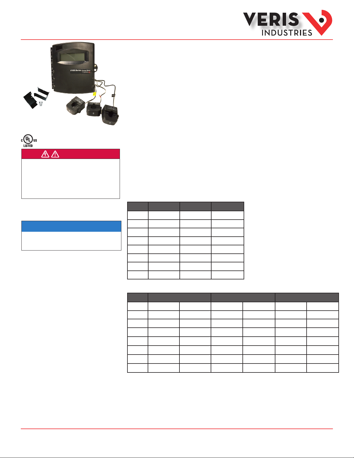
Product Overview
The H81xx Series energy meter combines industrial-grade split-core current transformers and precision
microprocessor-based metering electronics. It can detect phase reversal, eliminating load orientation concerns. The
meter and current transformers are calibrated as a set, so the installer must match their serial numbers at the time
of installation. The H8150 provides a control power voltage range of 90-132 VAC. The H8163 and H8167 provide an
extended input control power voltage range (90-300 VAC).
The H8163 and H8167 models also have a pulse output compatible with building control systems and a phase loss
output to protect equipment. All models include a slot to install a Modbus, BACnet, or Metasys communication
board (sold separately). When equipped with this board and connected to a data acquisition system, the H8163 and
H8167 can report energy and power diagnostic variables, including kWh, kW, PF, kVAR, Volts, and Amps.
Product Identification
120 VAC - 240 VAC (nom.); 90-132 VAC L-N; Display Only Output
Amps One CT Two CTs Three CTs
100 Micro H8150-0100-0-1 H8150-0100-0-2 H8150-0100-0-3
200 Mini H8150-0200-1-1 H8150-0200-1-2 H8150-0200-1-3
300 Small H8150-0300-2-1 H8150-0300-2-2 H8150-0300-2-3
400 Med H8150-0400-3-2 H8150-0400-3-3
800 Med H8150-0800-3-2 H8150-0800-3-3
800 Lg H8150-0800-4-3
1600 Lg H8150-1600-4-3
2400 Lg H8150-2400-4-3
120 VAC - 480 VAC (nom.); 90-300 VAC L-N; Pulse, Phase Loss, and Display Outputs
Amps One CT Two CTs Three CTs
100 Micro H8163-0100-0-1 H8167-0100-0-1 H8163-0100-0-2 H8167-0100-0-2 H8163-0100-0-3 H8167-0100-0-3
200 Mini H8163-0200-1-1 H8167-0200-1-1 H8163-0200-1-2 H8167-0200-1-2 H8163-0200-1-3 H8167-0200-1-3
300 Small H8163-0300-2-1 H8167-0300-2-1 H8163-0300-2-2 H8167-0300-2-2 H8163-0300-2-3 H8167-0300-2-3
400 Med H8163-0400-3-2 H8167-0400-3-2 H8163-0400-3-3 H8167-0400-3-3
800 Med H8163-0800-3-2 H8167-0800-3-2 H8163-0800-3-3 H8167-0800-3-3
800 Lg H8163-0800-4-3 H8167-0800-4-3
1600 Lg H8163-1600-4-3 H8167-1600-4-3
2400 Lg H8163-2400-4-3 H8167-2400-4-3
Z205338-0F Page 1 of 10 ©2013 Veris Industries USA 800.354.8556 or +1.503.598.4564 / support@veris.com 09132
Alta Labs, E nercept, Ensp ector, Hawkeye, Trus tat, Aerospo nd, Veris, and th e Veris ‘V’ log o are tradema rks or registe red tradema rks of Veris Ind ustries, L. L.C. in the USA and /or other countri es.
Other companies’ trademarks are hereby acknowledged to belong to their respective owners.
Page 2
Installation Guide
Power Monitoring
H81xx
TM
Product Identification
(cont.)
Specifications
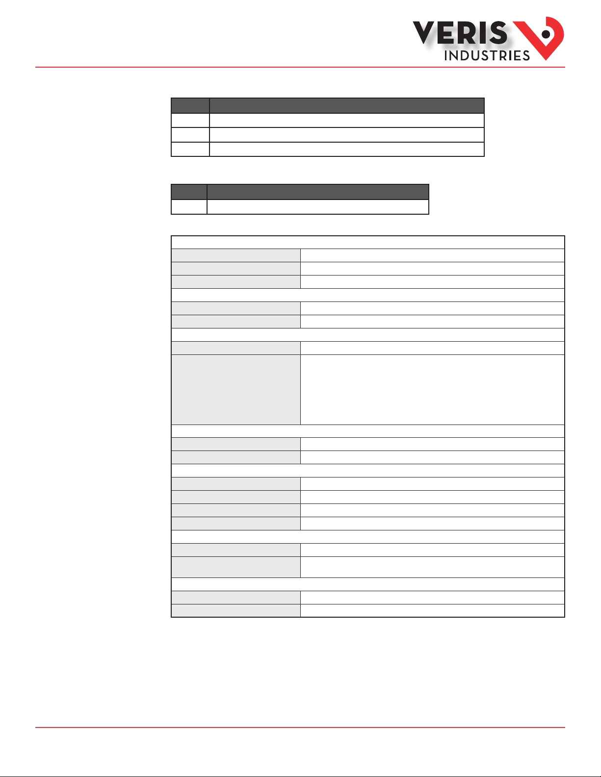
Optional Comm Board (sold separately)
Model Description
H8163-CB Modbus® Communications Board for H81xx Series
H8186-CB BACnet® Communications Board for H81xx Series
H8126-CB Metasys® N2 Communications Board for H81xx Series (consult factory if ordering this item)
Optional Accessory
Model Description
AH06 Mounting Bracket Kit (ts the Small, Medium, and Large CTs only)
INP UTS
H8150
H8163, H8167
Frequency
System Accuracy
Sample Rate
All Models
H8163 and H8167
PULS E OUTP UT
PU L S E R AT E
PU LS E W IDTH
PHASE LOSS ALARM OUTPUT
Protection Class
Insulation Class
Operating Temperature Range
Storage Temperature Range
Humidity Range
Altitude of Operation
H8150
H8163, H8167
Agency Approvals
Installation Category
* Meters and current transformers are calibrated as a set. To achieve this accuracy, match the serial numbers on the current
transformers and the meter at the time of installation (does not apply to 100 A CTs).
** Do not apply 600V class current transformers to circuits having a phase-to-phase voltage greater than 600V without adequate
additional insulation between primary conductor and current transformers.
90 to 132VAC line-to-neutral
90 to 300VAC line-to-neutral
50 /60 Hz
ACCUR ACY
±1% of reading from 2% to 100% of the C T current rating *
128 0 H z
OUTPUTS
1.2” x 3.8” ( 31 mm x 97 mm) viewing area, 16 0 segments, backlit LCD
N.O., Opto -FET, 100mA@ 24VAC/DC
0.10, 0.25, 0. 50, 1.0 0 kWh per pulse ( jumper selectable)
200msec closed
H8163 : N.O. ( opens on alarm, remains open while alarm persists) ;
H8167: N.C. (closes on alarm, remains closed while alarm persists);
Both H816 3 and H8167: Opto-Fet, 100m A@ 24VAC /DC;
Fixed threshold 25% below any other phase
MECHAN ICAL
NEMA 1
600 VAC **
OPERATING CO NDITIO NS
0° to 50 °C ( 32° to 122°F )
-4 0°C to 70°C ( -40° to 158 °F )
0-95% RH, non-condensing
0 to 200 0 m
ELECTRICAL SERVICES
120/240 VAC with neutral, 208Y/120 VAC line-to-neutral
Any Wye service in which the phase L-N voltage is ≤ 300VAC and the phase-tophase volt age is ≤ 480 VAC nom. with neutral
COMPLIANCE INFORMATION
UL 61010
Cat III, pollution degree 2
Z205338-0F Page 2 of 10 ©2013 Veris Industries USA 800.354.8556 or +1.503.598.4564 / support@veris.com 09132
Alta Labs, E nercept, Ensp ector, Hawkeye, Trus tat, Aerospo nd, Veris, and th e Veris ‘V’ log o are tradema rks or registe red tradema rks of Veris Ind ustries, L. L.C. in the USA and /or other countri es.
Other companies’ trademarks are hereby acknowledged to belong to their respective owners.
Page 3
Installation Guide
3"
(77 mm)
7.6"
(193 mm)
8.3"
(211mm)
14.8"
(375 mm)
A
B
E
F
C
D
B
E
F
C
D
A
A
B
E
C
F
D
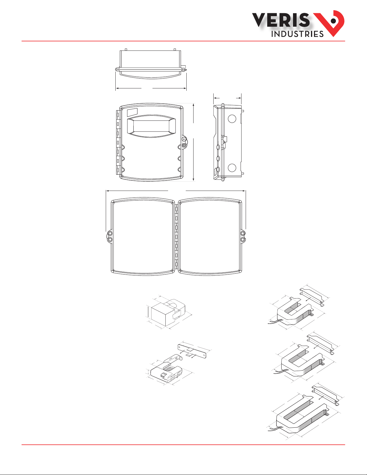
A = 2.6" (66 mm)
B = 1.1" (28 mm)
C = 0.8" (19 mm)
D = 1" (27 mm)
E = 2.9" (74 mm)
F = 3.5" (90 mm)
MINI
200 Amp
A = 4.9" (124 mm)
B = 2.9" (73 mm)
C = 2.5" (62 mm)
D = 1.1" (29 mm)
E = 5.6" (141 mm)
F = 5.9" (150 mm)
MEDIUM
400/800 Amp
A = 3.8" (95 mm)
B = 1.5" (38 mm)
C = 1.3" (32 mm)
D = 1.1" (29 mm)
E = 4.2" (107 mm)
F = 4.8" (121 mm)
SMALL
300 Amp
A = 4.9" (124 mm)
B = 5.5" (140 mm)
C = 2.5" (62 mm)
D = 1.1" (29 mm)
E = 8.1" (207 mm)
F = 5.9" (150 mm)
LARGE
800/1600/2400 Amp
F
E
D
C
B
A
MICRO
100 Amp
A = 1.6” (40 mm)
B = 0.7” (16 mm)
C = 0.7” (16 mm)
D = 1.2” (29 mm)
E = 2.1” (53 mm)
E
A
B
C
D
Power Monitoring
H81xx
Dimensions
TM
Z205338-0F Page 3 of 10 ©2013 Veris Industries USA 800.354.8556 or +1.503.598.4564 / support@veris.com 09132
Alta Labs, E nercept, Ensp ector, Hawkeye, Trus tat, Aerospo nd, Veris, and th e Veris ‘V’ log o are tradema rks or registe red tradema rks of Veris Ind ustries, L. L.C. in the USA and /or other countri es.
Other companies’ trademarks are hereby acknowledged to belong to their respective owners.
Page 4

Installation Guide
* Comm board is optional and sold as a separate product.
Power Monitoring
H81xx
TM
Product Diagram
H81xx Series Cover
1
C US
H8163/H8167 Inside and Board Layout
Comm Board Slot *
8
9
2
U
L
®
3
Plain
7
Power Supply Board Slot
Black
Red
Yellow
+-+ - + -
+ A D + B D + C D
Display
10
Full
Black
Red
N A B C
N A
5 6
Yellow
B C
4
H8150 Inside and Board Layout
Comm Board Slot *
Power
Supply
Black
Red
+-+ - + -
+ A D + B D + C D
Display
Plain
Full
10
Black
Yellow
Red
Yellow
N A B C
4
N A
B C
8
9
3
* Comm board is optional and sold as a separate product.
1. Display. Large digit backlit LCD for data and diagnostics.
2. Security hasp.
3. Current transformer input terminals. These ensure that voltage lead and current transformer are properly matched (e.g. red to
red ).
4. Voltage input terminals. These ensure that voltage lead and current transformer are properly matched (e.g. red to red).
5. Pulse output terminals. These provide easy integration to existing control/data acquisition systems. (H8163 and H8167)
6. Phase loss output alarm. Alarm trips to protect equipment if phase voltage drops 25%. (H8163 and H8167)
7. Pulse rate selection switch. Set the pulse output at 0.1, 0.25, 0.50, or 1 pulse/kWh to match resolution requirements. (H8163
and H8167)
8. kWh reset. To reset the kWh counter, push both buttons at the same time and hold for 10 seconds. To reset kW max, push both
buttons and hold for 5 seconds.
9. Backlight enabling jumper. Remove this jumper to disable lighting.
10. Plain/full display data jumper. 20 or 90 second display cycle.
Z205338-0F Page 4 of 10 ©2013 Veris Industries USA 800.354.8556 or +1.503.598.4564 / support@veris.com 09132
Alta Labs, E nercept, Ensp ector, Hawkeye, Trus tat, Aerospo nd, Veris, and th e Veris ‘V’ log o are tradema rks or registe red tradema rks of Veris Ind ustries, L. L.C. in the USA and /or other countri es.
Other companies’ trademarks are hereby acknowledged to belong to their respective owners.
Page 5

Installation Guide
Power Monitoring
H81xx
TM
Installation
Disconnect and lock out all power sources during installation and conguration.
If making connections to the meter through more than one metallic conduit, use a bonding
plate (Veris part number AH11 or equivalent) to prevent electric shock.
1. Verify that the serial number on the meter matches the serial numbers on the current transformers (CTs). These are calibrated
as a set, and mixing transformers with non-matching meters may damage the device when power is applied. The meter’s serial
number is printed on the label axed to the inside of the front cover, and the CT serial number is on the CT label. If using 100 A
CTs, serial number matching does not apply.
Match serial numbers
between meters an d CTs.
Serial number matching does
not apply if using 100 A CTs.
2. Mount the meter.
3. Attach the CTs to the conductors. Local code requirements may require a mounting bracket. For maximum accuracy, run the
conductor through the center of the current transformer window.
4. Optional step, per NEC and local regulations: Attach external fuses (not included with the H81xx devices). Verify that the fuse
rating is adequate for the applied voltage, with a current rating of ½ Amp (T) slow blow. Select fuses with a fault current rating
that matches the power source rating.
Use fuses compatib le with this meter:
Single phase Veris AH02
Two phase Veris AH03
Three phase Veris AH04
1/2A (T) SLO-BLO
ØA
ØB
ØC
N
Installer Supplied Fuses
Accessory bonding
plate or equivalent
required when more
than one metallic
conduit will be used.
Bond multiple
metallic conduit
runs with available
bonding plate
(Veris AH11 or equivalent)
VERIS INDUSTRIES
1-800-354-8556
Shock Hazard!
CONTROLLER
Z205338-0F Page 5 of 10 ©2013 Veris Industries USA 800.354.8556 or +1.503.598.4564 / support@veris.com 09132
Alta Labs, E nercept, Ensp ector, Hawkeye, Trus tat, Aerospo nd, Veris, and th e Veris ‘V’ log o are tradema rks or registe red tradema rks of Veris Ind ustries, L. L.C. in the USA and /or other countri es.
Other companies’ trademarks are hereby acknowledged to belong to their respective owners.
Page 6

Installation Guide
Power Monitoring
H81xx
TM
Installation (cont.)
5. Use color coding to attach current transformer (CT) leads to the input terminals (e.g. red labeled lead to red terminal). Polarity
is indicated in the wiring diagrams, but the meter is not polarity sensitive. See the Wiring section.
6. Use color coding to connect voltage leads to phase conduc tors (e.g. red transformer lead to red terminal). The meter is powered
from the monitored source, so connect the voltage leads to a circuit that is normally left on. See the Wiring section.
7. H8163 and H8167: Connect the output terminals to the control/data acquisition system. The Pulse Output is normally open. For
the H8163, the Phase Loss Output is normally open, and for the H8167, it is normally closed. Both are rated for 24 VAC/VDC@100
mA maximum. Ensure that the installation method and insulation ratings conform to local and national electrical codes.
Display
Plain
Full
Black
Red
+-+ - + -
+ A D + B D + C D
Black
Yellow
Red
Yellow
N A B C
N A
B C
Pulse Output
Terminal
Phase Loss
Output
Terminal
8. Set the backlight enabling jumper as desired. Remove the jumper to disable the backlight.
Backlight Enable Jumper
9. Set the Display Data jumper for either Plain or Full settings. Plain mode c ycles the display through ve data elements (kW, max.
kW since last reset, average PF, line-to-line voltage, and amps) for four seconds each. Full mode cycles through all of the data
available in the meter. See the Information Reporting section for more details.
20 seconds per cycle
kW
max. kW
PF
Volts L-L
Amps
90 seconds per cycle
kW
max. kW
PF
Volts L-L
Amps
kVAR
kW Phase A
kW Phase B
kW Phase C
PF Phase A
etc.
Z205338-0F Page 6 of 10 ©2013 Veris Industries USA 800.354.8556 or +1.503.598.4564 / support@veris.com 09132
Alta Labs, E nercept, Ensp ector, Hawkeye, Trus tat, Aerospo nd, Veris, and th e Veris ‘V’ log o are tradema rks or registe red tradema rks of Veris Ind ustries, L. L.C. in the USA and /or other countri es.
Other companies’ trademarks are hereby acknowledged to belong to their respective owners.
Page 7

Installation Guide
Power Monitoring
H81xx
TM
Installation (cont.)
10. H8163 and H8167: Set the Pulse Rate selection switch to the desired output rate (kWh per pulse). Note that 0.1 is not valid for
1600 A systems, and 0.1 and 0.25 are not valid for 2400 A systems.
1.0
0.5
0.25
0.1
Display
Plain
Full
Black
Black
Red
Yellow
Red
Yellow
+-+ - + -
N A B C
N A
B C
+ A D + B D + C D
11. Secure the meter cover shut using a padlock, wire tie, or other locking device.
12. Apply power to the meter.
13. Check the display. At initial power-up, the meter checks each phase. If the phasing is correct, an OKAY message appears. If
the phasing is incorrec t, an error message indicates which color leads are not connected properly. Disconnect power before
reconnecting leads.
14. Check the power reading. Expected power is estimated as follows:
kW = Volts(L-L) * Amps * 1.732 * PF 1000
kW = horsepower * 0.746
15. To reset the kWh accumulator to zero, press and hold the two pushbuttons on the inside of the meter cover for 10 seconds.
16. To reset the kW max. register, press and hold the two pushbuttons on the inside of the meter cover for 5 seconds.
Z205338-0F Page 7 of 10 ©2013 Veris Industries USA 800.354.8556 or +1.503.598.4564 / support@veris.com 09132
Alta Labs, E nercept, Ensp ector, Hawkeye, Trus tat, Aerospo nd, Veris, and th e Veris ‘V’ log o are tradema rks or registe red tradema rks of Veris Ind ustries, L. L.C. in the USA and /or other countri es.
Other companies’ trademarks are hereby acknowledged to belong to their respective owners.
Page 8

Installation Guide
Power Monitoring
H81xx
TM
Wiring
Connect the white wire to (-). Connect the red/black/yellow wire to (+).
Typical 208/480VAC, ** 4-Wire, 3Ø Installation
RED CT
ØA
BLACK CT
ØB
Red
+ A Ð + B Ð + C Ð
YELLOW CT
ØC
WHITE
*
*
N
*
Typical 240/120 VAC, 3-Wire, 1Ø Installation
RED CT
ØA
BLACK CT
ØB
Red
+ A – + B – + C –
Black
Black
Yellow
Yellow
White
Red
N A B C
N A
White
Red
N A B C
N A
B C
B C
Black
Black
Yellow
Yellow
WHITE
*
N
*
Typical 120 VAC, 2-Wire, 1Ø Installation
RED CT
Ø A
WHITE
N
*
* External f use provided by installer (optiona l, per NEC and local regulations).
** 480 VAC only applie s to the H8163 and H8167.
Red
Black
+ A – + B – + C –
Yellow
Red
White
N A B C
N A
B C
Black
Yellow
Z205338-0F Page 8 of 10 ©2013 Veris Industries USA 800.354.8556 or +1.503.598.4564 / support@veris.com 09132
Alta Labs, E nercept, Ensp ector, Hawkeye, Trus tat, Aerospo nd, Veris, and th e Veris ‘V’ log o are tradema rks or registe red tradema rks of Veris Ind ustries, L. L.C. in the USA and /or other countri es.
Other companies’ trademarks are hereby acknowledged to belong to their respective owners.
Page 9

Installation Guide
Power Monitoring
H81xx
TM
Alarms
Data Outputs
The following messages remain on the lower display for the duration of an alarm condition:
Message Explanation
Phase loss The voltage on one phase is less than 75% of the voltage on any other
Amps Over The measured current is greater than 110% of the transformer range. The
Volts Over Volts A-C, B-C, or A-C is greater than 660VAC.* The displayed message
*
The H8163 and H8167 are rated to 300 VAC L-N, and the H8150 is rated to 132 VAC L-N. Operation above the se levels damages the device.
phase. The displayed message indicates the problem phase.
display message indicates the problem phase.
indicates the problem phase.
The H81xx continually reports kWh or MWh, depending on the total accumulated energy. A secondary display cycles through other
parameters. The meter has two modes of display operation, depending on the setting of the Display Data jumper (J8) on the main
circuit board. In Full Display mode, the meter cycles through all parameters. In Plain Display mode, the meter cycles through only
the rst ve parameters as listed below:
kW
Max. kW
PF
Volts
Amps
kVAR
kW, phase A *
kW, phase B *
kW, phase C **
PF, phase A *
PF, phase B *
PF, phase C **
Volts, A-B **
Volts, B-C **
Volts, A-C **
Volts, A-N *
Volts, B-N *
Volts, C-N **
Amps, A *
Amps, B *
Amps, C **
If the H81xx has a communication board installed, every 10th rotation of parameters displays an additional set of data values:
Pulse Rate ***
Address
Baud Rate
Parity
2/4 Wire
* For meters with 2 or 3 c urrent transformers.
** For meters with 3 cu rrent transformers.
*** H8163 and H8167 o nly.
Z205338-0F Page 9 of 10 ©2013 Veris Industries USA 800.354.8556 or +1.503.598.4564 / support@veris.com 09132
Alta Labs, E nercept, Ensp ector, Hawkeye, Trus tat, Aerospo nd, Veris, and th e Veris ‘V’ log o are tradema rks or registe red tradema rks of Veris Ind ustries, L. L.C. in the USA and /or other countri es.
Other companies’ trademarks are hereby acknowledged to belong to their respective owners.
Page 10

Installation Guide
Power Monitoring
H81xx
TM
Troubleshooting
Problem Solution
No display · Check external fuses.
· Verify that the display cable has not been disconnected during installation.
· Verify voltage leads are properly connected.
Reported power too low · Verify CTs and terminals are color-matched.
· Check for phase loss.
· Check external fuses.
Reported power inaccurate Verify meter and CTs have matching serial numbers (serial number matching does not apply if using
Accuracy not as specied · Verify CTs and terminals are color-matched.
No Pulse output (H8163 and H8167) · Verify power is supplied in the range of 5-24 VAC/DC, with a max. load of 100 mA.
Pulse output wrong, display OK (H8163
and H8167)
No Phase Loss output (H8163 and
H8167)
“bAd” appears in the display (H8163
and H8167)
Accuracy not as specied Verify current transformers and terminals are color-matched.
100 A CTs).
· Verify that no stray conductive materials (wire clippings, etc.) have shorted between the terminals.
· The pulse output internal is 200 msec; verify the controller accepts this signal as input.
Set the pulse rate switch and the controller to match kWh/pulse.
Verify power is supplied in the range of 5-24 VAC/DC, with a max. load of 100 mA.
Verify that the Pulse Rate slide switch is set to a valid value. 0.1 is not valid for 1600 A systems; 0.1
and 0.25 are not valid for 2400 A systems.
Z205338-0F Page 10 of 10 ©2013 Veris Industries USA 800.354.8556 or +1.503.598.4564 / support@veris.com 09132
Alta Labs, E nercept, Ensp ector, Hawkeye, Trus tat, Aerospo nd, Veris, and th e Veris ‘V’ log o are tradema rks or registe red tradema rks of Veris Ind ustries, L. L.C. in the USA and /or other countri es.
Other companies’ trademarks are hereby acknowledged to belong to their respective owners.
 Loading...