

Page 1
TM
the user will be required to correct the interference at his own expense.
Power MoNITorING
INSTALLATIoN GUIDe
H8186 - CB
DANGER
HAZARD OF ELECTRIC SHOCK, EXPLOSION, OR ARC FLASH
• Follow safe electrical work practices. See NFPA 70E in the USA, or applicable local codes.
• This equipment must only be installed and serviced by qualified electrical personnel.
• Read, understand and follow the instructions before installing this product.
• Turn off all power supplying equipment before working on or inside the equipment.
• Use a properly rated voltage sensing device to confirm power is off.
DO NOT DEPEND ON THIS PRODUCT FOR VOLTAGE INDICATION
• Only install this product on insulated conductors.
Failure to follow these instructions will result in death or serious injury.
NOTICE
• This product is not intended for life or safety applications.
• Do not install this product in hazardous or classified locations.
• The installer is responsible for conformance to all applicable codes.
• Mount this product inside a suitable fire and electrical enclosure.
FCC PART 15 INFORMATION
NOTE: This equipment has been tested by the manufacturer and found
to comply with the limits for a class A digital device, pursuant to part
15 of the FCC Rules. These limits are designed to provide reasonable
protection against harmful interference when the equipment is
operated in a commercial environment. This equipment generates,
uses, and can radiate radio frequency energy and, if not installed and
used in accordance with the instruction manual, may cause harmful
interference to radio communications. Operation of this equipment in
a residential area is likely to cause harmful interference in which case
Modifications to this product without the express authorization of
Veris Industries nullify this statement.
Product identification
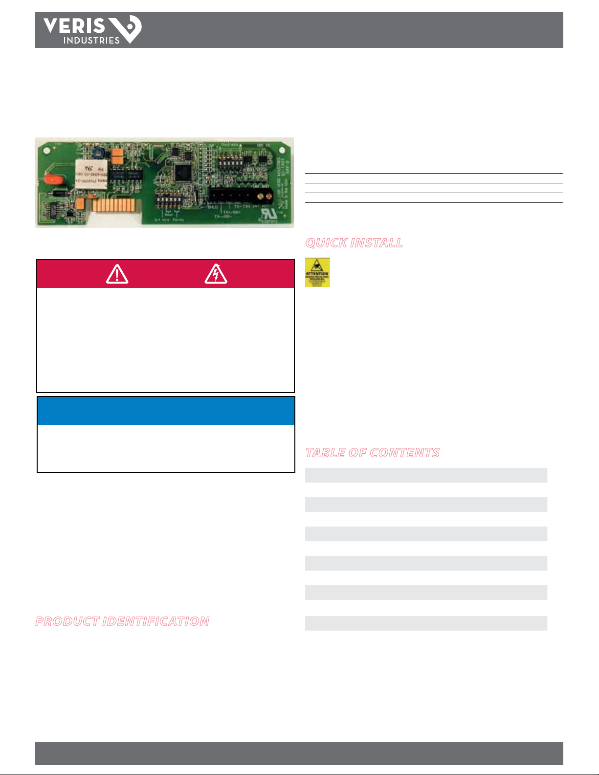
H8186-CB BACnet Communications Board for H81xx Energy Meter
H8186 - CB
BACnet Communication Board
for the H81xx Energy Meter
Installer’s Specifications
Output Type BACnet
Connection 2-wire
Baud Rate 9600, 19200, 38400
Address Range 1-63
quick install
H81xxCB Series interfaces are sold as open devices.
Observe handling precautions for static sensitive
devices to avoid damage to the circuitry which
would not be covered under the factory warranty.
1. Turn o all power to the energy meter and the equipment in which it is installed.
2. Discharge static.
3. Slide the H8186-CB into the channels on either side of the energy meter until the
male connection on the meter clicks into place.
4. Insert the communication terminal onto the RS-485 communication terminals.
5. If the demand subinterval feature is used, wire it into the end of the demand
subinterval terminal.
6. Replace the voltage terminal into the energy meter.
table of contents
Operation 2
Data Output Specications 2
Product Diagram 2
Conguration 3
RS-485 Communications Setup 3
Wiring 4
Installing the H8186-CB in the Energy Meter 5
Troubleshooting 5
BACnet MAC Address Setup 6
BACnet Descriptions 7
BACnet Protocol 8
Z204062-0F PAGE 1 ©2012 Veris Industries USA 800.354.8556 or +1.503.598.4564 / support@veris.com 02122
Alta Labs, Enercep t, Enspector, Hawkeye, Trustat, Veris, and the Veris ‘ V’ logo are trademark s or registered tradema rks of Veris Industries, L.L .C. in the USA and /or other count ries.
Page 2
TM
ON
123 456
ON
123 456
1 2
TX RX
3RX4
TX
5
6
7
8
9
ALIVE
LITHIUM BATTERY
H8186-CB
INSTALLATIoN GUIDe
oPeration
H8186-CB energy meter communication board is an optional eld-installable plugand-play accessory board for the H81xx energy meter that allows networking the
H81xx to an existing BACnet MS/TP control/data acquisition system. It features eld
selectable baud rate (9600, 19200, 38400).
data outPut sPecifications
kWh, Consumption
kW, Real power
kVAR, Reactive power
kVA, Apparent power
Power fac tor
Voltage, line to line
Voltage, line to neutral
Amps, Average current
kW, Real power ØA
kW, Real power ØB
kW, Real power ØC
Power factor ØA
Power factor ØB
Power factor ØC
Voltage, ØA to ØB
Voltage, ØB to ØC
Voltage, ØA to ØC
Voltage, ØA to Neutral
Voltage, ØB to Neutral
Voltage, ØC to Neutral
Amps, Current ØA
Amps, Current ØB
Amps, Current ØC
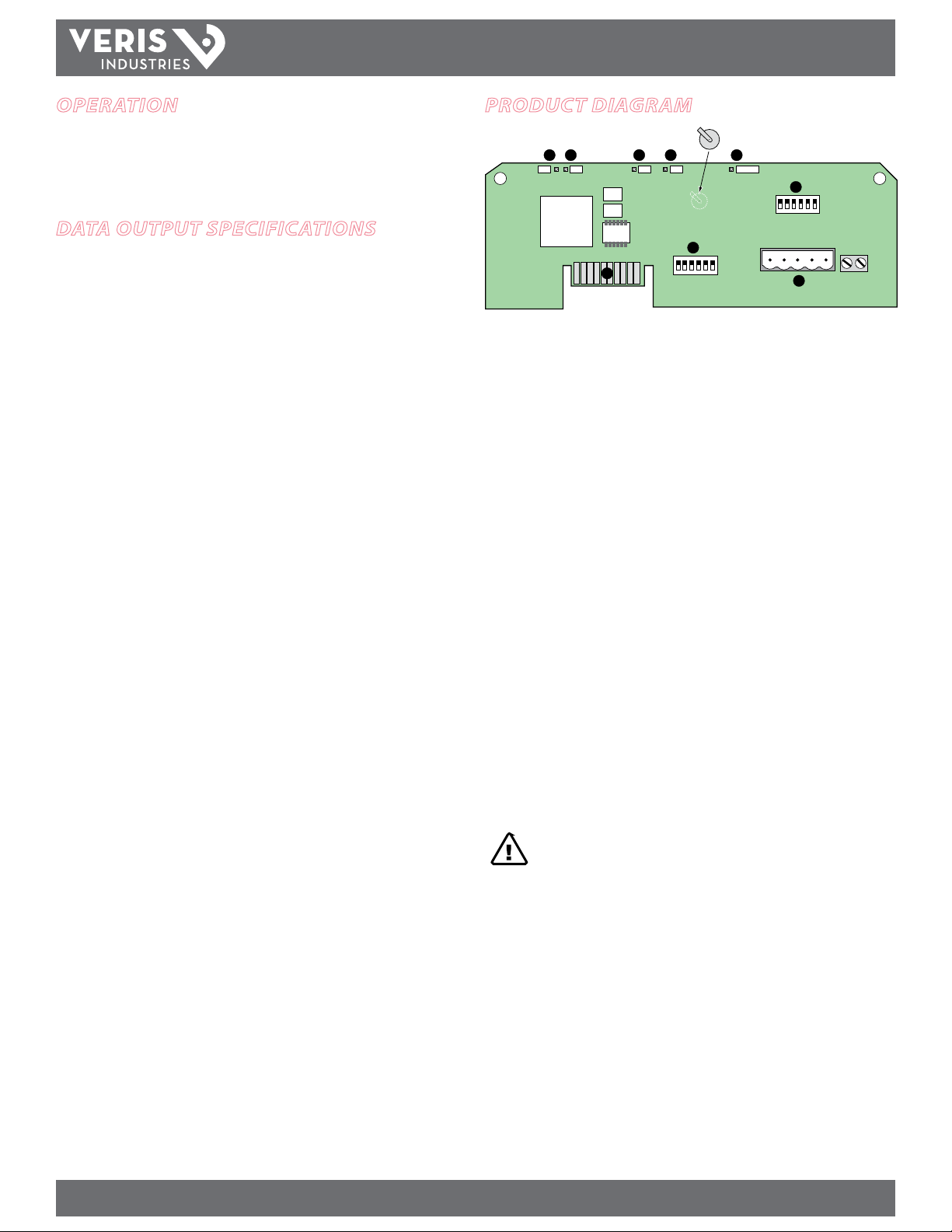
Product diagram
1. RS-485 LED (TX): Red LED; blinks to indicate that the H8186-CB is transmitting
data to the master.
2. RS-485 LED (RX): Red LED; blinks to indicate that the H8186-CB is receiving data
from the master.
3. LED from Main Board (RX): Green LED; blinks to indicate that the H8186-CB is
receiving data from the main board.
4. LED from Main Board (TX): Green LED; blinks to indicate that the H8186-CB is
transmitting data to the main board.
5. “ALIVE” LED: Green LED; should blink once per second to indicate normal
operation of the H8186-CB.
6. Network Address DIP Switches: Use these DIP switches to set the network
address for the H8186-CB.
7. Connection to Energy Meter: Install the H8186-CB in the energy meter by
inserting this connector into the connection slot at the top of the energy meter.
8. Communication DIP Switches: Use these DIP switches to set the H8186-CB
baud rate.
9. RS-485 Communication Terminals: Insert the RS-485 connector into these
terminals. See the Wiring Diagram section of this guide for instructions on wiring
the connector for 2-wire communications.
CAUTION! Danger of explosion if battery is incorrectly
replaced. Replace only with the same or equivalent type
recommended by the manufacturer. Dispose of used batteries according to the manufacturer’s instructions.
Z204062-0F PAGE 2 ©2012 Veris Industries USA 800.354.8556 or +1.503.598.4564 / support@veris.com 02122
Alta Labs, Enercep t, Enspector, Hawkeye, Trustat, Veris, and the Veris ‘ V’ logo are trademark s or registered tradema rks of Veris Industries, L.L .C. in the USA and /or other count ries.
Page 3
TM
8 + 32 = 40
Wiring Baud Parity
Power MoNITorING
INSTALLATIoN GUIDe
configuration
This section describes the communications settings you must make to the H8186-CB.
When daisy-chaining devices, follow these guidelines:
• Connect up to 63 H8186-CB devices on a single daisy chain.
• Each H8186-CB device on the daisy chain must have a unique address.
Before connecting the H8186-CB to the RS-485 communication wires,
set the address according to directions in “Selecting the Network Address
DIP Switches” on this page. If you assign the same address to two devices,
neither device will communicate.
• Set the baud rate according to directions in “Selecting Baud Rate —
Communication DIP Switches.” The settings for each H8186-CB must
match the other devices on its daisy chain.
• For RS-485 cables, use shielded, twisted-pair wire (Belden Cable 1120A or
equivalent).
• If the H8186-CB is the last device, terminate it per the RS-485 standard
(120 Ω nominal impedence).
Selecting The Network Address DIP Switches
Use the Network Address DIP switches to select the network address. Each H8186-CB
on a daisy chain must have a unique network address (from 0 to 63). Devices with the
same address will be unable to communicate.
Always set the address before you install the H8186-CB in the energy meter and
before you connect the energy meter to the daisy chain.
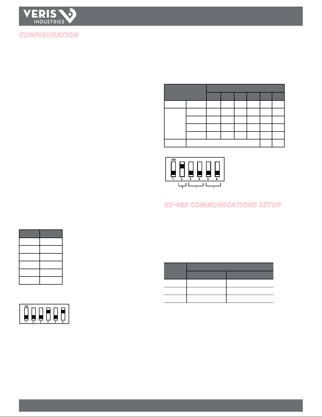
Each of the six DIP switches has a unique address value, page 6 lists DIP switch
positions for specic addresses.
Network Address DIP Switch Values
Switch Value
1 1
2 2
3 4
4 8
5 16
6 32
In this example, the network address for the device
is 40. Switch 4 and 6 oer the only combination of
values that total 40.
This gure illustrates how to set the switches. Up is
ON; down is OFF.
Selecting Baud Rate – Communication DIP Switches
Use the communication DIP switches (pictured below) to set the H8186-CB baud rate.
The gures below list the baud rate switch settings and the location of these
switches.
Wiring and Baud Rate Settings
Parameter Switch Number and Setting
1 2 3 4 5 6
Wire Type 2-wire – ON
9600 – OFF OFF
Baud Rate
Parity Not applicable to this model. OFF OFF
19200 – ON OFF
38400 – OFF ON
38400 – ON ON
Switches 1, 5, and 6 are unused. Always leave
them in the OFF position.
This example illustrates the default switch
settings for a 2-wire device that uses 9600
baud rate.
Parity function is not applicable to this model;
leave these switches in the OFF position.
rs-485 communications setuP
Daisy Chain Maximum Distances
The maximum number of devices capable of being supported on a single daisy chain
is determined based on the combination of baud rate, the length of the daisy chain,
and the types of RS-485 devices on the daisy chain. The RS-485 interface will support
daisy chains that fall within the specications shown below.
2-Wire Daisy Chain Maximum Distances
Baud Rate Maximum Distances
1-8 Devices 9-16 Devices
9600 10000 ft. (3048 m) 4000 ft. (1219 m)
19200 5000 ft. (1,524 m) 2500 ft. (762 m)
38400 2500 ft. (762 m) 1200 ft. (380 m)
Wiring the Connector
Remove the connector from the RS-485 communication terminals of the H8186-CB
(see Wiring Diagram section). To wire RS-485 communications, follow these steps:
1. Wire the communications connector for 2-wire communication (see Wiring
Diagram section). The Wire Type setting in the communication DIP switch must
match this wiring type (set Switch 2 to the ON position; see Selecting Baud Rate
section).
2. Use a small, at-blade screwdriver to tighten the connector screws.
3. Replace the connector on the RS-485 communication terminals of the H8186-CB.
4. If the H8186-CB is the last device on the daisy chain, terminate it to ensure reliable
communication per the RS-485 standard (120 Ω nominal impedence).
Z204062-0F PAGE 3 ©2012 Veris Industries USA 800.354.8556 or +1.503.598.4564 / support@veris.com 02122
Alta Labs, Enercep t, Enspector, Hawkeye, Trustat, Veris, and the Veris ‘ V’ logo are trademark s or registered tradema rks of Veris Industries, L.L .C. in the USA and /or other count ries.
Page 4

wiring
TX+
SHLD
TX+
RX+
TX–
RX–
TX–
SHIELD
ON
123456
ON
123 456
TX RX RX ALIVE
SHLD
TX-/RX-
TX+/RX+
TX-TX+
TX+
SHLD
TX+
RX+
TX–
RX–
TX–
MASTER SLAVE
TM
H8186-CB
INSTALLATIoN GUIDe
2-wire Communications Wiring
* If the H8186-CB is the last device in a daisy
chain, terminate it to ensure reliable
communication per the RS-485 standard
(120 Ω nominal impedence).
Z204062-0F PAGE 4 ©2012 Veris Industries USA 800.354.8556 or +1.503.598.4564 / support@veris.com 02122
Alta Labs, Enercep t, Enspector, Hawkeye, Trustat, Veris, and the Veris ‘ V’ logo are trademark s or registered tradema rks of Veris Industries, L.L .C. in the USA and /or other count ries.
Page 5

TM
SLOTS
TOP
COMMS BOARD
BATTERY
CONNECTORS
CONNECTION
SLOTS
ON
1 2
TX RX
3RX4
TX
5
6
ALIVE
D5 D6 D13 D14 D1
H8186-CB
INSTALLATIoN GUIDe
installing the h8186-cb in the
energy meter
Before beginning this procedure, set the baud rate using the Communication DIP
switches, and set the network address using the Network Address DIP switches (see
the Conguration section on page 3 of this installation guide).
1. Turn o all power to the energy meter and the equipment in which it is
installed:
a. Remove the voltage terminal from the energy meter and all fuses.
b. Always use a properly rated voltage sensing device to conrm that
power is o.
2. To discharge static, follow the instructions that come with your anti-static
or grounding strap. Use an anti-static or grounding strap at all times during
installation.
3. Slide the H8186-CB into the slot in the H81xx energy meter. The sides of the
H8186-CB slide down into the channels on either side of the energy meter. When
the male connection to the energy meter (see below) clicks into place, the H8186CB is properly installed.
Observe handling precautions for static sensitive
devices to avoid damage to the circuitry which
would not be covered under the factory warranty.
troubleshooting
If communications are not working properly, rst check that the board is properly
seated in its slot in the energy meter, and that the connector has clicked into place in
the connection slot on the meter.
There are ve LEDs that indicate various types of communication.
LED Abnormal Operation Solution
1 RS-485 LED
(TX)
2 RS-485 (RX) Not Blinking There is no communication from the
3 From main
board (RX)
4 From main
board (TX)
5 “Alive” status Steadily lit Diagnostic event detected. Contact the
Not Blinking There is no communication from the
H8163 to the master. Check the
wiring; TX+/TX- and RX+/RX- may be
reversed. Correct the wiring. If RX is
blinking, verify the DIP switch address,
baud rate, and wire type.
master. The RX+ and RX- wires are
reversed. Correct the wiring.
Not blinking The main board is not responding.
Contact the factory for support.
Not blinking but “Alive”
LED is blinking
Diagnostic event detected. Contact the
factory.
factory for support.
4. Insert the communication terminal onto the RS-485 communication
terminals.
5. If the demand sub-interval feature is used, wire into the end of the demand
sub-interval terminal.
6. Replace the voltage terminal into the energy meter.
Z204062-0F PAGE 5 ©2012 Veris Industries USA 800.354.8556 or +1.503.598.4564 / support@veris.com 02122
Alta Labs, Enercep t, Enspector, Hawkeye, Trustat, Veris, and the Veris ‘ V’ logo are trademark s or registered tradema rks of Veris Industries, L.L .C. in the USA and /or other count ries.
Page 6

TM
91
H8186-CB
INSTALLATIoN GUIDe
bacnet mac address setuP
The gure below illustrates the switch settings, using the network address DIP switches, for each network address. See “Selecting the Network Address DIP Switches” on
page 2 for instruction on setting the switches.
0
1
2
345678
11 12 13 14 15 16 17 18 19 20 21
22 23 24 25 26 27 28 29 30 31
32
0
33 34 35 36 37 38 39 40 41 42 43
44 45 46 47 48 49 50 51 52 53 54
55 56 57 58 59 60 61 62 63
Z204062-0F PAGE 6 ©2012 Veris Industries USA 800.354.8556 or +1.503.598.4564 / support@veris.com 02122
Alta Labs, Enercep t, Enspector, Hawkeye, Trustat, Veris, and the Veris ‘ V’ logo are trademark s or registered tradema rks of Veris Industries, L.L .C. in the USA and /or other count ries.
Page 7

TM
bacnet descriPtions
BACnet Object Description Description Field Units
H8186-CB
Device Object This device Veris H81xx Energy Meter
with H8186-CB BACnet
Communications Board
Analog Value Object 1 Accumulated Energy kWh_Total kWh
Analog Value Object 2 Device Instance Device_Instance N/A
Analog Input Object 1 Total Real Power kW_Total kW
Analog Input Object 2 Total Reactive Power kVAR_Total kW
Analog Input Object 3 Total Apparent Power kVA_Total kW
Analog Input Object 4 Total Power Factor PF_Total Unitless
Analog Input Object 5 Average Line -Line Voltage Volts_LL_Avg Volts
Analog Input Object 6 Average Line -Nuetral Voltage Volts_LN_Avg Volts
Analog Input Object 7 Average Current Current_Avg Amps
Analog Input Object 8 Real Power: Phase A kW_A kW
Analog Input Object 9 Real Power: Phase B kW_B kW
Analog Input Object 10 Real Power: Phase C kW_C kW
Analog Input Object 11 Power Factor: Phase A PF_A Unitless
Analog Input Object 12 Power Factor: Phase B PF_B Unitless
Analog Input Object 13 Power Factor: Phase C PF_C Unitless
Analog Input Object 14 Voltage: Phase A-Phase B Volts_AB Volts
Analog Input Object 15 Voltage: Phase B-Phase C Volts_BC Volts
Analog Input Object 16 Voltage: Phase A-Phase C Volts_AC Volts
Analog Input Object 17 Voltage: Phase A-Neutral Volts_AN Volts
Analog Input Object 18 Voltage: Phase B-Neutral Volts_BN Volts
Analog Input Object 19 Voltage: Phase C-Neutral Volts_CN Volts
Analog Input Object 20 Current: Phase A Current_A Amps
Analog Input Object 21 Current: Phase B Current_A Amps
Analog Input Object 22 Current: Phase C Current_A Amps
N/A
INSTALLATIoN GUIDe
Clear the kWh accumulator to zero by writing 0.0 to the PRESENT_VALUE property Analog Value Object 1.
Changing the Device_Instance:
• Units are shipped with a default Device Instance of 123.
• There are 2 methods of changing the Device_Instance:
1. Write the Object_Identier directly. The Device’s Object_Identier contains both the Object_Type (Device = 8) and the Object_Instance (0-4194302). Write
the Device’s Object_Identier with (8,Instance) to change the Device_Instance.
2. Use Analog Value Object 2. Although a REAL (i.e. oating point) value, writing the Present_Value of AV2 is an alternative method of changing the Device_
Instance. This value may be written in the range 0-4194302. Any fractional value will be truncated (e.g. 57.234 will be written as 57).
Z204062-0F PAGE 7 ©2012 Veris Industries USA 800.354.8556 or +1.503.598.4564 / support@veris.com 02122
Alta Labs, Enercep t, Enspector, Hawkeye, Trustat, Veris, and the Veris ‘ V’ logo are trademark s or registered tradema rks of Veris Industries, L.L .C. in the USA and /or other count ries.
Page 8

TM
bacnet Protocol
H8186-CB
INSTALLATIoN GUIDe
BACnet Protocol Implementation Conformance Statement
Date: August 2, 2007
Vendor Name: Veris Industries
Product Name: BACnet Communications Board for
H81xx Energy Meter
Product Model Number: H818 6-CB
Applications Software Version: 1
Firmware Revision: 1. 09
BACnet Protocol Revision: 2
Product Description: Provides BACnet MS/TP connectivity to
the Veris H81xx Energy Meter
BACnet Standardized Device Profile (Annex L):
BACnet Application Specic Controller (B-ASC)
List all BACnet Interoperability Building Blocks Supported (Annex K):
DS-RP-B, DS-RPM-B, DS-WP-B, DM-DDB-B, DM-DOB-B, DM-DCC-B
Segmentation Capability:
Segmentation not supported
Standard Object Types Supported:
No dynamic Creation or Deletion supported
No proprietary properties or object types
Device Object:
Optional Properties Supported:
Max_Master, Max_Info_Frames, Description, Location
Writable Properties:
Object_Identier, Max_Master, Location
Property Range Restrictions:
Location (limited to 64 characters)
Analog Value Object:
Optional Properties Supported:
Description
Writable Properties:
Only the Present_Value is writable.
Property Range Restrictions:
1) Only the value 0.0 may be written to the Present_Value
of AV1. This action will clear the kWh-Accumulator in the
H81xx Energy Meter.
2) Although a REAL (i.e. oating point) value, writing the
Present_Value of AV2 is an alternative method of changing
the Device_Instance. This value may be written in the range
0-4194302. Any fractional value will be truncated (eg. 57.234
will be written as 57).
Data Link Layer Options:
MS/TP master (Clause 9), baud rate(s): 9600, 19200, 38400
Device Address Binding:
Static device binding is not suppor ted. (No client functionality is included).
Networking Options:
None
Character Sets Supported:
ANSI X3.4
Analog Input Object:
Optional Properties Supported:
Description
No Writable Properties.
Z204062-0F PAGE 8 ©2012 Veris Industries USA 800.354.8556 or +1.503.598.4564 / support@veris.com 02122
Alta Labs, Enercep t, Enspector, Hawkeye, Trustat, Veris, and the Veris ‘ V’ logo are trademark s or registered tradema rks of Veris Industries, L.L .C. in the USA and /or other count ries.
 Loading...