

Page 1
TM
the user will be required to correct the interference at his own expense.
POWER MONITORING
INSTALLATION GUIDE
H8163 - CB
DANGER
HAZARD OF ELECTRIC SHOCK, EXPLOSION, OR ARC FLASH
• Follow safe electrical work practices. See NFPA 70E in the USA, or applicable local codes.
• This equipment must only be installed and serviced by qualified electrical personnel.
• Read, understand and follow the instructions before installing this product.
• Turn off all power supplying equipment before working on or inside the equipment.
• Use a properly rated voltage sensing device to confirm power is off.
DO NOT DEPEND ON THIS PRODUCT FOR VOLTAGE INDICATION
• Only install this product on insulated conductors.
Failure to follow these instructions will result in death or serious injury.
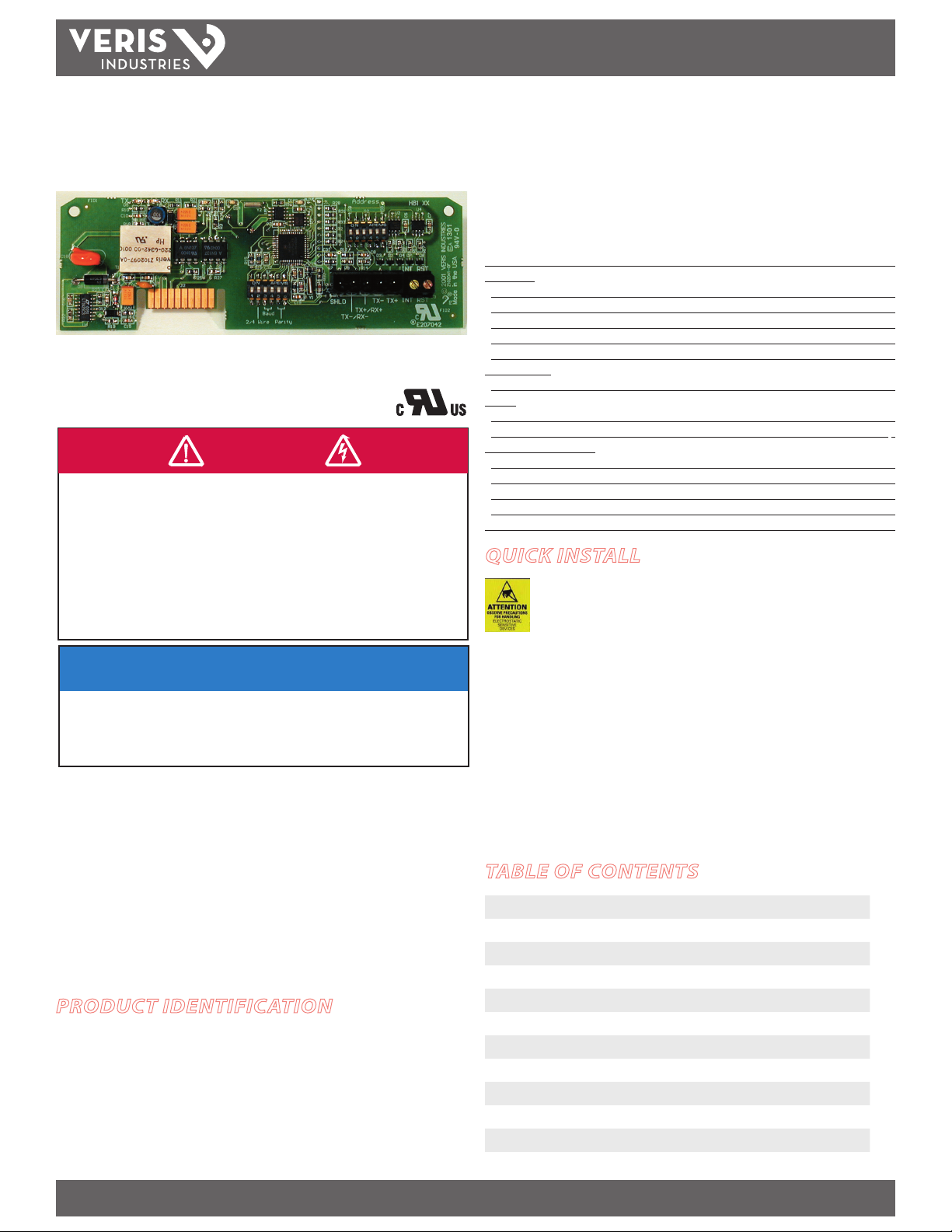
H8163 - CB
Modbus Communication Board
for the H81xx Energy Meter
Installer Specifications
Communication Protocols Modbus RTU
Connection:
RS-485 Up to 63 devices
2-wire or 4-wire Field selectable
Baud Rate 2400, 4800, 9600, 19200 baud, select able
Parity None/Odd/Even, selectable
Address Range DIP switch selectable (1-63)
External Inputs:
Demand Syncronizing or Pulse Counting Field selectable
Wiring:
Terminal Block Screw Torque 0.37 ft-lb (0.5 N·m) nominal/0.44 ft-lb (0.6 N·m) max.
Terminal Block Wire Size 26 to 14 AWG (0.13 to 2.08 mm2)
Environmental Conditions:
Operating Temperature 0° to 50°C (32° to 122°F)
Storage Temperature -40° to 70°C (-4 0° to 158°F)
Humidity Range 0 to 95% RH (non-condensing)
Altitude of Operation 0-2000 m
Agency Approvals UL 3111 Cat. III pollution degree 2
QUICK INSTALL
Observe precautions for handling static sensitive
devices to avoid damage to the circuitry that
is not covered under the factory warranty.
1. Disconnect power to the meter.
NOTICE
2. Set the DIP switches for appropriate network addressing.
• This product is not intended for life or safety applications.
• Do not install this product in hazardous or classified locations.
• The installer is responsible for conformance to all applicable codes.
• Mount this product inside a suitable fire and electrical enclosure.
FCC PART 15 INFORMATION
NOTE: This equipment has been tested by the manufacturer and found
to comply with the limits for a class A digital device, pursuant to part
15 of the FCC Rules. These limits are designed to provide reasonable
protection against harmful interference when the equipment is
operated in a commercial environment. This equipment generates,
uses, and can radiate radio frequency energy and, if not installed and
used in accordance with the instruction manual, may cause harmful
interference to radio communications. Operation of this equipment in
a residential area is likely to cause harmful interference in which case
Modifications to this product without the express authorization of
Veris Industries nullify this statement.
PRODUCT IDENTIFICATION
H8163-CB Modbus Communication Board for H81xx Energy Meter
Z202879-0D PAGE 1 ©2012 Veris Industries USA 800.354.8556 or +1.503.598.4564 / support@veris.com 03122
Alta Labs, Enercep t, Enspector, Hawkeye, Trustat, Veris, and the Veris ‘ V’ logo are trademark s or registered tradema rks of Veris Industries, L.L .C. in the USA and /or other count ries.
3. Wire the communications terminals for 2-wire or 4-wire communication.
4. Disconnect power to the energy meter. Discharge static using an anti-static or
grounding strap.
5. Still using the anti-static strap, install the H8163-CB into the slot in the energy
meter until the board clicks into place.
6. Restore power to the meter.
TABLE OF CONTENTS
Operation 2
Data Output Specications 2
Product Diagram 2
Conguration 3
RS-485 Communications Setup 3
Wiring 4
Installing the H8163-CB in the Energy Meter 5
Modbus Address Setup 6
Modbus Point Map 7
Multiplier Table 10
Divisor Table 11
Notes 12
Page 2
H8163-CB
ON
1 2 3 4 5 6
ON
1 2 3 4 5 6
1 2
TX RX
3
RX
4
TX
5
6
7
8
9 10
ALIVE
LITHIUM BATTERY
10
TM
INSTALLATION GUIDE
OPERATION
The H8163-CB energy meter communication board is an optional eld-installable
board for the H8163 energy meter that allows Modbus RTU communication. The
H8163-CB also enables the energy meter to provide true kW & kVAR demand
information.
The easy-to-install H8163-CB provides a simple, cost-eective way to network the
H8163 energy meter on a Modbus network.
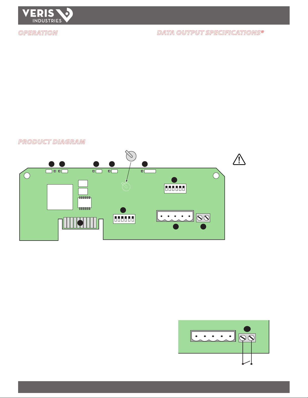
PRODUCT DIAGRAM
DATA OUTPUT SPECIFICATIONS*
kWh, Consumption
kW, Real power
kVAR, Reactive power
kVA, Apparent power
Power fac tor
Voltage, line to line
Voltage, line to neutral
Amps, Average current
kW, Real Power ØA
kW, Real Power ØB
kW, Real Power ØC
Power factor ØA
Power factor ØB
Power factor ØC
* See the Modbus Point Map on w ww.veris.com for a full list of data input /output features.
Voltage, ØA to ØB
Voltage, ØB to ØC
Voltage, ØA to ØC
Voltage, ØA to Neutral
Voltage, ØB to Neutral
Voltage, ØC to Neutral
Amps, Current ØA
Amps, Current ØB
Amps, Current ØC
kW, Demand
kVAR, Demand
kW, Peak Demand
kVAR, Peak Demand
CAUTION! Danger of
explosion if battery is
incorrectly replaced.
Replace only with the same
or equivalent type. Dispose
of used batteries according
to applicable environmental
laws.
1. RS-485 LED (TX): Red LED; blinks to indicate data transmission from the H8163-
CB to the master.
8. Communication DIP Switches: Use these DIP switches to set the H8163-CB
wiring type, baud rate, and parity. See “Setting the Communication DIP Switches”
on page 3 for instructions.
2. RS-485 LED (RX): Red LED; blinks to indicate data reception from the master to
the H8163-CB.
9. RS-485 Communication Terminals: Insert the RS-485 connector into these
terminals. See Wiring Diagrams on page 4 for instructions on wiring the connector
3. LED from Main Board (RX): Green LED; blinks to indicate data reception from
for 2-wire or 4-wire communications.
the main board.
10. Input Connector: Use this terminal as the input connector for “end of demand
4. LED from Main Board (TX): Green LED; blinks to indicate data transmission to
the main board.
5. ALIVE LED: Green LED; should blink once per second to indicate normal operation.
6. Network Address DIP Switches: Use these DIP switches to set the network
address for the H8163-CB. See the Settings table on page 3 for more information.
7. Connection to Energy Meter: Install the H8163-CB in the energy meter by
inserting this connector into the connection slot at the top of the energy meter.
Z202879-0D PAGE 2 ©2012 Veris Industries USA 800.354.8556 or +1.503.598.4564 / support@veris.com 03122
Alta Labs, Enercep t, Enspector, Hawkeye, Trustat, Veris, and the Veris ‘ V’ logo are trademark s or registered tradema rks of Veris Industries, L.L .C. in the USA and /or other count ries.
interval” signal from the utility or other source. Use an interposing isolated relay
as the dry contac t for this terminal, as pictured below.
Page 3
H8163-CB
WiringBaud Parit
y
Red
Black
Gray
Use 14-24 gauge wire
TM
CONFIGURATION
This section describes the communications settings you must make to the H8163-CB.
When daisy-chaining Modbus devices, follow these guidelines:
• Connect up to 63 H8163-CB devices on a single daisy chain.
• Each H8163-CB device on the daisy chain must have a unique address.
Before connecting the H8163-CB to the RS-485 communication wires,
set the address according to directions on this page.
• Set the wiring type, baud rate, and parity according to directions in
“Selecting Wiring Type, Baud Rate, and Parity Settings” on this page. The
settings for each H8163-CB must match the other devices on its daisy
chain.
• For RS-485 cables, use shielded, twisted-pair wire (Belden Cable 1120A or
equivalent).
• Terminate the last device on the daisy chain to ensure reliable
communication per the RS-485 standard (120 Ω nominal impedence).
Selecting The Network Address DIP Switches
Use the network address DIP switches to select the network address. Each H8163-CB
on a daisy chain must have a unique network address (from 1 to 63). Devices with the
same address as another on the chain will be unable to communicate.
Always set the address before you install the H8163-CB in the energy meter and
before you connect the energy meter to the daisy chain.
Each of the six DIP switches has a unique address value. The Modbus Addressing
section on page 6 lists DIP switch positions for specic addresses.
INSTALLATION GUIDE
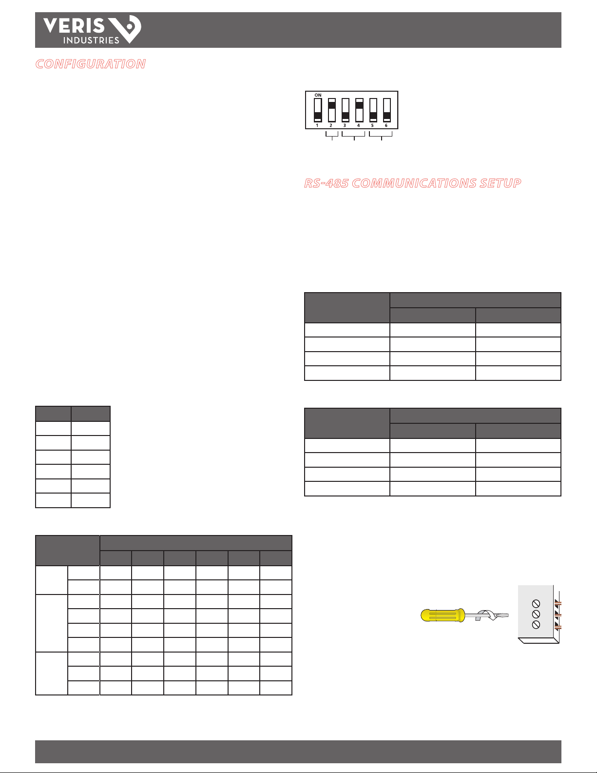
Setting the Communication DIP Switches
Switch 1 is unused. Always leave it in the OFF
position.
This example illustrates the default switch settings
for a 2-wire device that uses 9600 baud rate with
no p arit y.
RS-485 COMMUNICATIONS SETUP
Daisy Chain Maximum Distances
The maximum number of devices allowed on a single daisy chain is determined by
combining the baud rate, the length of the daisy chain, and the types of RS-485
devices (2-wire/4-wire) on the chain. The RS-485 interface will support daisy chains
that fall within the specications shown below.
4-Wire Daisy Chain Maximum Distances
Baud Rate Maximum Distances
1-16 Devices 17-32 Devices
2400 10,000 ft. (3048 m) 5000 ft. (1524 m)
4800 10,000 ft. (3048 m) 5000 ft. (1524 m)
9600 10,000 ft. (3048 m) 4000 ft. (1219 m)
19200 5000 ft. (1524 m) 2500 ft. (762 m)
Network Address DIP Switch Values
Switch Value
1 1
2 2
3 4
4 8
5 16
6 32
Selecting Wiring, Baud Rate, and Parity Settings
Parameter Switch Number and Setting
1 2 3 4 5 6
Wire
Type
Baud
Rate
Parity
2-wire - On
4-wire - O
2400 - O O
4800 - On O
9600 - O On
19200 - On On
None - O O
Even - On O
Odd - On On
2-Wire Daisy Chain Maximum Distances
Baud Rate Maximum Distances
1-8 Devices 9-16 Devices
2400 10,000 ft. (3048 m) 5000 ft. (1524 m)
4800 10,000 ft. (3048 m) 5000 ft. (1524 m)
9600 10,000 ft. (3048 m) 4000 ft. (1219 m)
19200 5000 ft. (1524 m) 2500 ft. (762 m)
Wiring the Connector
1. Remove the connector from the RS-485 communication terminals of the H8163CB.
2. Wire the communications connector as shown on page 4 (2-wire or 4-wire
communication). The wire type set ting in the communication DIP switch must
match this wiring type.
3. Use a small, at-blade screwdriver
to tighten the connector screws.
Apply the correct torque: 0.37-0.44
ft·lb (0.5-0.6 N·m).
4. Replace the connector on the RS-485 communication terminals of the H8163-CB.
5. If the H8163-CB is the last device in a daisy chain, terminate it to ensure reliable
communication per the RS-485 standard (120 Ω nominal impedence).
0.37–0.44 ft•lb
(0.5–0.6 N•m)
Z202879-0D PAGE 3 ©2012 Veris Industries USA 800.354.8556 or +1.503.598.4564 / support@veris.com 03122
Alta Labs, Enercep t, Enspector, Hawkeye, Trustat, Veris, and the Veris ‘ V’ logo are trademark s or registered tradema rks of Veris Industries, L.L .C. in the USA and /or other count ries.
Page 4
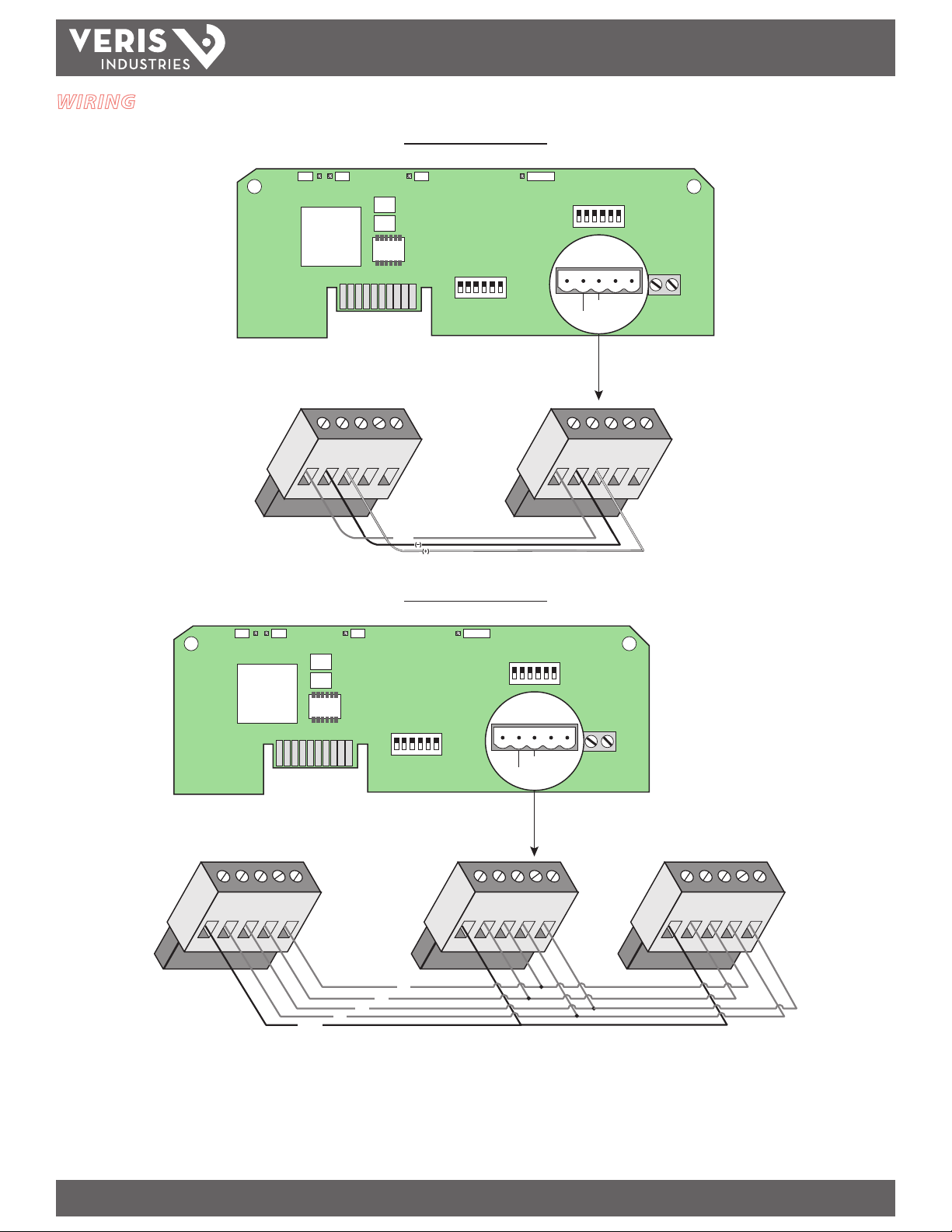
WIRING
TX+
SHLD
TX+
RX+
TX–
RX–
TX–
SHIELD
ON
123456
ON
123 456
TX RX RX ALIVE
SHLD
TX-/RX-
TX+/RX+
TX-TX+
TX+
SHLD
TX+
RX+
TX–
RX–
TX–
MASTER SLAVE
ON
123456
ON
123456
TX RX RX ALIVE
SHLD
TX-/RX-
TX+/RX+
TX-TX+
TX+
SHLD
TX+
RX+
TX–
RX–
TX–
TX+
SHLD
RX+
RX–
TX–
TX+
SHLD
TX+
RX+
TX–
RX–
TX–
SHIELD
RX-
RX+
TX-
TX+
MASTER SLAVESLAVE
H8163-CB
TM
INSTALLATION GUIDE
2-Wire Communications *
4-Wire Communications *
* If the H8163-CB is the last device in a daisy cha in, terminate it to ensure reliable communication per the RS-485 standa rd (120 Ω nominal impedence).
Z202879-0D PAGE 4 ©2012 Veris Industries USA 800.354.8556 or +1.503.598.4564 / support@veris.com 03122
Alta Labs, Enercep t, Enspector, Hawkeye, Trustat, Veris, and the Veris ‘ V’ logo are trademark s or registered tradema rks of Veris Industries, L.L .C. in the USA and /or other count ries.
Page 5

H8163-CB
SLOTS
TOP
COMMS BOARD
BATTERY
CONNECTORS
CONNECTION
SLOTS
ON
1 2
TX RX
3
RX
4
TX
5
6
ALIVE
D5 D6 D13 D14 D1
TM
INSTALLING THE H8163-CB IN THE
ENERGY METER
Complete the Communications Setup and Wiring instructions
before installing the board inside the meter.
The H8163-CB is designed as a plug-and-play accessory for the H8163 energy meter.
Follow these instructions to install the H8163-CB into the energy meter.
1. Turn o all power to the energy meter and the equipment in which it is installed.
INSTALLATION GUIDE
a. Remove the voltage terminal from the energy meter and all fuses.
b. Always use a properly rated voltage sensing device to conrm that power
is o.
2. To discharge static, follow the instructions that come with your anti-static or
grounding strap. We recommend using an anti-static or grounding strap until the
installation is complete.
3. Slide the H8163-CB into the slot in the H8163 housing. The sides of the H8163CB slide down into the channels on either side of the energy meter. When the
male connection to the H8163 board clicks into place, the H8163-CB is properly
installed.
4. Insert the communication terminal onto the RS-485 communication terminals.
5. If the demand subinterval feature is used, wire into the end of demand subinterval
terminal.
6. Replace the voltage terminal into the energy meter.
TROUBLESHOOTING
If communications are not working properly, rst check that the board is properly
seated in its slot in the energy meter, and that the connector has clicked into place in
the connection slot on the meter.
There are ve LEDs that indicate various types of communication.
Observe precautions for handling static sensitive
devices to avoid damage to the circuitry that
is not covered under the factory warranty.
During normal operation, all ve LEDs will blink regularly. When an error occurs, the
abnormal LED will help determine where that error is.
LED
LED Description Abnormal Operation Solution
Number
1 RS-485 (TX) Not blinking No communication from the H8163 to the master.
· Check the wiring; TX+/TX- and RX+/RX- may be reversed. Correct the wiring.
· If RX is blinking, verify the DIP switch address, parity, baud rate, and wire type.
2 RS-485 (RX) Not blinking No communication from the master. The RX+/RX- may be reversed. Correct the wiring.
3 From main board (RX) Not blinking Main board not responding. Contact customer support for assistance.
4 From main board (TX) Not blinking but “Alive”
5 “Alive” status Steadily lit Internal communications board diagnostic event. Contact customer support for assistance.
Z202879-0D PAGE 5 ©2012 Veris Industries USA 800.354.8556 or +1.503.598.4564 / support@veris.com 03122
Alta Labs, Enercep t, Enspector, Hawkeye, Trustat, Veris, and the Veris ‘ V’ logo are trademark s or registered tradema rks of Veris Industries, L.L .C. in the USA and /or other count ries.
LED is blinking
Internal communications board diagnostic event. Contact customer support for assistance.
Page 6

H8163-CB
32
33 34 35 36 37 38 39 40 41 42 43
44 45 46 47 48 49 50 51 52 53 54
55 56 57 58 59 60 61 62 63
0
11
22 23 24 25 26 27 28 29 30 31
12 13 14 15 16 17 18 19 20 21
1 234 5 678 910
TM
INSTALLATION GUIDE
MODBUS ADDRESS SETUP
The gure below illustrates the network address DIP switch settings for each network address. See “Selecting the Network Address DIP Switches” on page 3 for instructions on
setting the switches.
Z202879-0D PAGE 6 ©2012 Veris Industries USA 800.354.8556 or +1.503.598.4564 / support@veris.com 03122
Alta Labs, Enercep t, Enspector, Hawkeye, Trustat, Veris, and the Veris ‘ V’ logo are trademark s or registered tradema rks of Veris Industries, L.L .C. in the USA and /or other count ries.
Page 7

H8163-CB
TM
INSTALLATION GUIDE
MODBUS POINT MAP
Int Float R/W NV Model Description Notes
1 257/258 R NV Energy Consumption, kWh, Low-word integer
2 259/260 R NV Energy Consumption, kWh, High-word integer
3 261/262 R Real Power, kW
4 263/264 R Reactive Power, kVAR
5 265/266 R Apparant Power, kVA
6 267/268 R Total Power Factor
R -1 Not Applicable - reads 0xFFFF/NaN (int/oat)
7 269/270
8 271/272
9 273/274
10 275/276
11 277/278
12 279/280
13 281/282
14 283/284
15 285/286
16 287/288
17 289/290
18 291/292
19 293/294
20 295/296
21 297/298
22 299/300
R -1 Avg Voltage, L-N, ave of 1
R -2 Avg Voltage, L-N, ave of 2
R -3 Avg Voltage, L-N, ave of 3
R -1 Avg Current, average of 1
R -2 Avg Current, average of 2
R -3 Avg Current, average of 3
R -1 Real Power, phase A (same as Real Power, kW (3))
R -1 Not Applicable – reads as 0xFFFF/NaN (int/oat)
R -1/-2 Not Applicable – reads as 0xFFFF/NaN (int/oat)
R -1 Power Factor, phase A (Same as Total PF (6))
R -1 Not Applicable – reads 0xFFFF/NaN (int/oat)
R -1/-2 Not Applicable – reads 0xFFFF/NaN (int/oat)
R -1 Not Applicable – reads 0xFFFF/NaN (int/oat)
R -1/-2 Not Applicable – reads 0xFFFF/NaN (int/oat)
R -1/-2 Not Applicable – reads 0xFFFF/NaN (int/oat)
R -1 Voltage, phase A-N (Same as Avg. L-N (8))
R -1 Not Applicable – reads 0xFFFF/NaN (int/oat)
R -1/-2 Not Applicable – reads 0xFFFF/NaN (int/oat)
R -1 Current, phase A (Same as Avg. Current (9))
-2 Avg Voltage, L-L, ave of 1
-3 Avg Voltage, L-L, ave of 3
-2/-3 Real Power, phase A
-2/3 Real Power, phase B
-3 Real Power, phase C
-2/-3 Power Factor, phase A
-2/-3 Power Factor, phase B
-3 Power Factor, phase C
-2/-3 Voltage, phase A-B
-3 Voltage, phase B-C
-3 Voltage, phase A-C
-2/-3 Voltage, phase A-N
-2/-3 Voltage, phase B-N
-3 Voltage, phase C-N
-2/-3 Current, phase A
Both 257/258 and 259/260 have the same oating point value.
R: R = Read-only, R/W = read fro m either format, write to integer format only
NV: Value is stored in non-volatile memory
Z202879-0D PAGE 7 ©2012 Veris Industries USA 800.354.8556 or +1.503.598.4564 / support@veris.com 03122
Alta Labs, Enercep t, Enspector, Hawkeye, Trustat, Veris, and the Veris ‘ V’ logo are trademark s or registered tradema rks of Veris Industries, L.L .C. in the USA and /or other count ries.
Page 8

H8163-CB
TM
INSTALLATION GUIDE
Int Float R/W NV Model Description Notes
23 301/302
24 303/304
25 305/306 R Present Demand Sub-Interval
26 307/308 R Present Demand (kW)
27 309/310 R NV Peak Demand
28 311/312 R Present kVAR Sub-Interval
29 313/314 R Present kVAR
30 315/316 R NV Peak kVAR The highest kVAR value (register 28) that has occurred.
31 R NV Count of kWh resets
32 R NV Count of Peak Demand Resets
33 R NV Count of Peak kVAR Resets
34 R Count of elapsed Sub-Intervals
35 R Number Readings in Present Sub-Interval
36 R/W NV Sub-Interval Length
37 R/W NV Number of Sub-Intervals per Demand Interval
38 R NV System ID
39 R NV CT Size This register reads as the CT size, 100, 300, etc.
40 R NV CT Number The number of CTs that are connected, 1, 2, or 3.
R -1 Not Applicable – reads 0xFFFF/NaN (int/oat)
-2/-3 Current, phase B
R -1/-2 Not Applicable – reads 0xFFFF/NaN (int/oat)
-3 Current, phase C
The currently accumulating sub-interval demand, which is
constantly changing.
The present demand, updated at the end of every sub-interval. This
value is the average of the previous N sub-intervals, where N is
the number of sub-intervals (register 37).
The highest demand value (register 26) that has occurred. This
value is also displayed on LCD for MAX kW when the comms
board is present.
The currently accumulating sub-interval kVAR, which is constantly
changing.
The present kVAR, updated at the end of every sub-interval. This
value is the average of the previous N sub-intervals, where N is
the number of sub-intervals (register 37).
The number of times the kWh accumulator has been reset. This
value can never be reset. It will roll over from 65535 to zero.
The number of times the peak demand (register 27) has been
reset. This value can never be reset. It will roll over from 65535
to zero.
The number of times the peak kVAR (register 30) has been reset.
This value can never be reset. It will roll over from 65535 to zero.
The number of sub-intervals that have elapsed. Because the
demand (register 28) is updated every sub-interval, read this
register to determine whether an identical value in register 28 is
actually the same demand interval or if it is a new interval and
the load has remained steady.
The number of readings that are represented by the present
sub-interval (register 25). This register acts as an unsigned
integer. See below for explaination of sub-interval reading count
overow. This register will increment every 200 msec (5 times
per second).
Sets the length of a sub-interval. Value is the number of seconds
* 5, e.g. 4500 is 15 minutes. For sync-to-comms or sync-todemand-reset-input (hardware signal), set this to zero.
Sets the number of sub-intervals that make a single demand
interval. Legal values are 1 to 6. For block demand, set this to 1.
This register reads as 15024 for the basic meter and 15025 for the
enhanced model to help identify the meter.
R: R = Read-only, R/W = read fro m either format, write to integer format only
NV: Value is stored in non-volatile memory
Z202879-0D PAGE 8 ©2012 Veris Industries USA 800.354.8556 or +1.503.598.4564 / support@veris.com 03122
Alta Labs, Enercep t, Enspector, Hawkeye, Trustat, Veris, and the Veris ‘ V’ logo are trademark s or registered tradema rks of Veris Industries, L.L .C. in the USA and /or other count ries.
Page 9

H8163-CB
TM
INSTALLATION GUIDE
Int Float R/W NV Model Description Notes
Command (bit mapped):
bit 0 (mask 1) = Begin New Demand Sub-Interval
bit 1 (mask 2) = Clear kWh accumulator
41 R/W
42 R/W NV
43 R NV Count of Phase Losses
44 R/W NV Date/Time Month 1-12 (LSB) Day 1-31 (MSB)
45 R/W NV Date/Time Year 0-199 (LSB) Hour 0-23 (MSB)
46 R/W NV Date/Time Minutes 0-59 (LSB) Seconds 0-59 (MSB)
47 R NV Phase Loss Timestamp, Month 1-12 (LSB) Day 1-31 (MSB)
48 R NV Phase Loss Timestamp, Year 0-199 (LSB) Hour 0-23 (MSB)
49 R NV Phase Loss Timestamp, Minutes 0-59 (LSB) Seconds 0-59 (MSB)
50 R NV Last Restart Timestamp, Month 1-12 (LSB) Day 1-31 (MSB)
51 R NV Last Restart Timestamp, Year 0-199 (LSB) Hour 0-23 (MSB)
52 R NV Last Restart Timestamp, Minutes 0-59 (LSB) Seconds 0-59 (MSB)
53 R NV Last KWh Reset Timestamp, Month 1-12 (LSB) Day 1-31 (MSB)
54 R NV Last KWh Reset Timestamp, Year 0-199 (LSB) Hour 0-23 (MSB)
55 R NV Last KWh Reset Timestamp, Minutes 0-59 (LSB) Seconds 0-59 (MSB)
56 R NV Reset System Firmware Version
57 R NV Operating System Firmware Version
58 R NV Serial Number LSW
59 R NV Serial Number MSW
bit 2 (mask 4) = Reset Peak Demand
bit 3 (mask 8) = Reset Peak kVAR
bits 4-15 = Write as zeros to avoid activating any additional commands that
might be added in future revisions
Phase Loss, Latching Register (bit mapped):
bit 0: phase A (unpredictable results on phase A)
bit 1: phase B
bit 2: phase C
bits 3 to 15 = write as zeros. This latching register should be cleared by user.
The number of times a phase loss has occurred on any phase. This
can never be reset and will roll over from 65535 to zero.
R: R = Read-only, R/W = read fro m either format, write to integer format only
NV: Value is stored in non-volatile memory
Z202879-0D PAGE 9 ©2012 Veris Industries USA 800.354.8556 or +1.503.598.4564 / support@veris.com 03122
Alta Labs, Enercep t, Enspector, Hawkeye, Trustat, Veris, and the Veris ‘ V’ logo are trademark s or registered tradema rks of Veris Industries, L.L .C. in the USA and /or other count ries.
Page 10

TM
MULTIPLIER TABLE
H8163-CB
INSTALLATION GUIDE
MB Point
100A 200A 300/400A 800A 1600A 2400A
kWh
1 kWh 0.007813 0.015625 0.03125 0.0625 0.125 0.25
2 kWh 512 1024 2048 4096 8192 16384
3 kW 0.004 0.008 0.016 0.032 0.064 0.128
4 kVAR 0.004 0.008 0.016 0.032 0.064 0.128
5 kVA 0.004 0.008 0.016 0.032 0.064 0.128
6 PF 3.05E-05 3.05E-05 3.05E-05 3.05E-05 3.05E-05 3.05E-05
7 V_LL 0.03125 0.03125 0.03125 0.03125 0.03125 0.03125
8 V_LN 0.015625 0.015625 0.015625 0.015625 0.015625 0.015625
9 Amps 0.003906 0.007813 0.015625 0.03125 0.0625 0.125
10 kW_a 0.001 0.002 0.004 0.008 0.016 0.032
11 kW_b 0.001 0.002 0.004 0.008 0.016 0.032
12 kW_c 0.001 0.002 0.004 0.008 0.016 0.032
13 PF_a 3.05E-05 3.05E-05 3.05E-05 3.05E-05 3.05E-05 3.05E-05
14 PF_b 3.05E-05 3.05E-05 3.05E-05 3.05E-05 3.05E-05 3.05E-05
15 PF_c 3.05E-05 3.05E-05 3.05E-05 3.05E-05 3.05E-05 3.05E-05
16 V_ab 0.03125 0.03125 0.03125 0.03125 0.03125 0.03125
17 V_bc 0.03125 0.03125 0.03125 0.03125 0.03125 0.03125
18 V_ac 0.03125 0.03125 0.03125 0.03125 0.03125 0.03125
19 V_an 0.015625 0.015625 0.015625 0.015625 0.015625 0.015625
20 V_bn 0.015625 0.015625 0.015625 0.015625 0.015625 0.015625
21 V_cn 0.015625 0.015625 0.015625 0.015625 0.015625 0.015625
22 Amps_a 0.003906 0.003906 0.003906 0.003906 0.003906 0.003906
23 Amps_b 0.003906 0.003906 0.003906 0.003906 0.003906 0.003906
24 Amps_c 0.003906 0.003906 0.003906 0.003906 0.003906 0.003906
25 kWd 0.004 0.008 0.016 0.032 0.064 0.128
26 kWd 0.004 0.008 0.016 0.032 0.064 0.128
27 kWd 0.004 0.008 0.016 0.032 0.064 0.128
28 kVARd 0.004 0.008 0.016 0.032 0.064 0.128
29 kVARd 0.004 0.008 0.016 0.032 0.064 0.128
30 kVARd 0.004 0.008 0.016 0.032 0.064 0.128
Unit/Description
Z202879-0D PAGE 10 ©2012 Veris Industries USA 800.354.8556 or +1.503.598.4564 / support@veris.com 03122
Alta Labs, Enercep t, Enspector, Hawkeye, Trustat, Veris, and the Veris ‘ V’ logo are trademark s or registered tradema rks of Veris Industries, L.L .C. in the USA and /or other count ries.
Page 11

DIVISOR TABLE
H8163-CB
TM
INSTALLATION GUIDE
MB Point
100A 200A 300/400A 800A 1600A 2400A
kWh
1 kWh 128 64 32 16 8 4
2 kWh 1.953E-3 9.765E-4 4.8828E-4 2.4414E-4 1.2207E-4 6.1035E-5
3 kW 250 125 62.5 31.25 15.625 7.8125
4 kVAR 250 125 62.5 31.25 15.625 7.8125
5 kVA 250 125 62.5 31.25 15.625 7.8125
6 PF 32768 32768 32768 32768 32768 32768
7 V_LL 32 32 32 32 32 32
8 V_LN 64 64 64 64 64 64
9 Amps 256 128 64 32 16 8
10 kW_a 1000 500 250 125 62.5 32.25
11 kW_b 1000 500 250 125 62.5 32.25
12 kW_c 1000 500 250 125 62.5 32.25
13 PF_a 32768 32768 32768 32768 32768 32768
14 PF_b 32768 32768 32768 32768 32768 32768
15 PF_c 32768 32768 32768 32768 32768 32768
16 V_ab 32 32 32 32 32 32
17 V_bc 32 32 32 32 32 32
18 V_ac 32 32 32 32 32 32
19 V_an 64 64 64 64 64 64
20 V_bn 64 64 64 64 64 64
21 V_cn 64 64 64 64 64 64
22 Amps_a 256 128 64 32 16 8
23 Amps_b 256 128 64 32 16 8
24 Amps_c 256 128 64 32 16 8
25 kWd 250 125 62.5 31.25 15.625 7.8125
26 kWd 250 125 62.5 31.25 15.625 7.8125
27 kWd 250 125 62.5 31.25 15.625 7.8125
28 kVARd 250 125 62.5 31.25 15.625 7.8125
29 kVARd 250 125 62.5 31.25 15.625 7.8125
30 kVARd 250 125 62.5 31.25 15.625 7.8125
Unit/Description
Z202879-0D PAG E 11 ©2012 Veris Industries USA 800.354.8556 or +1.503.598.4564 / support@veris.com 03122
Alta Labs, Enercep t, Enspector, Hawkeye, Trustat, Veris, and the Veris ‘ V’ logo are trademark s or registered tradema rks of Veris Industries, L.L .C. in the USA and /or other count ries.
Page 12

H8163-CB
TM
NOTES
Integer format registers represent the data as 16-bit integer values. Float format
registers represent the same data, as 32-bit oating point values.
For measured data, the oat format registers are recommended. The integer format
registers are dicult to use for the measured data, as a multiplier must be employed
for each to calculate the correct value. Most of the multipliers change, depending on
the CT size. Reading the oat format registers avoids the need to use multipliers.
Modbus Block Reads
There is no maximum block size restriction, as with the 80xx Series power meters, as
the entire Modbus response is fully buered. However, the total number of registers
requested may not exceed 125, as the Modbus protocol only allows up to 256 bytes.
125 registers * 2 bytes per register + 5 bytes overhead = 255 bytes.
INSTALLATION GUIDE
The maximum legal sub-interval length is 65535 readings, which corresponds to 3
hours, 38 minutes, 27.2 seconds. When the 65535th reading is taken, the sub-interval
reading counter overows. The H8163-CB detects this and ends the sub-interval. The
next sub-interval begins on the next reading. In normal operation, it is expected that
a sub-interval will not last longer than 1 hour.
When a sub-interval ends, the average kW/kVAR during that sub-interval (the
accumulated kW/kVAR readings divided by the number of readings) is added to a
six-value FIFO (rst in, rst out) that stores the six most recent sub-intervals. The kW/
kVAR accumulator and count of kW/kVAR readings are cleared to zero to begin a new
sub-interval. The count of sub-intervals (register 34) is incremented. The present
demand is recomputed by averaging the rst N elements of the FIFO, where N is
the value in register 37. If the new present demand is higher than the stored peak
demand, then the peak demand is updated to the new present demand.
Demand Computation, Internal Algorithm
The meter computes average kW/kVAR, by accumulating every kW/kVAR reading
and keeping a count of the number of kW/kVAR readings accumulated. This occurs
every 200 msec (5 Hz). The accumulated value, divided by the number of kW/kVAR
readings, is the present sub-interval demand (kW/kVAR), which is read at registers 25
(kW) and 28 (kVAR).
A sub-interval may be terminated in three ways.
1. If a write to the command register has bit #0 set.
2. If the hardware signal (interval reset) is detected.
3. If the sub-inter val length (register 36) is set to a nonzero level and the count of the
number of kW readings equals or exceeds the nonzero sub-interval length.
Although there are three ways to end a sub-interval, it is assumed that applications
will use only one of them.
Miscellaneous
Some registers list a model sux. These registers apply only to those models.
Registers that are not available for the particular model will read “0xFFFF” for integer
points and “NaN” for oating point registers.
The kW accumulator is reset by writing to the command register with bit #1 set. This
clears the kWh accumulator to zero. Any writes to the kWh points are ignored.
Floating Point Registers
All oating point values are compatible with the “32 bit IEEE real” format. All oating
point variables are read-only. All read/write points must be written to their integer
registers.
Z202879-0D PAGE 12 ©2012 Veris Industries USA 800.354.8556 or +1.503.598.4564 / support@veris.com 03122
Alta Labs, Enercep t, Enspector, Hawkeye, Trustat, Veris, and the Veris ‘ V’ logo are trademark s or registered tradema rks of Veris Industries, L.L .C. in the USA and /or other count ries.
 Loading...