

Page 1

Date: 31.07.2017
LD7 Installation
Manual
VERIPOS
Page 2

Procedure Title:
LD7 Installation Manual
File Ref.:
AB-V-MA-00559
Rev No:
A7
Page 2
REVISION
DATE
DESCRIPTION
ORIGINATOR
CHECKED
APPROVED
CLIENT APPR
A7
31.07.2017
Power consumption information
updated
AR
RR
RR
-
A6
13.11.2015
Updated antenna information
AR
RR
RR
-
A5
19.02.2015
Default IP settings updated
AR
EM
EM
-
A4
28.07.2014
Amended section 2.0
EM
RR
EM
-
A3
03.04.2014
Amend address, Helpdesk info
AW
RR
EM
-
A2
11.01.2014
Added Appendix I and II
EM
AW
EM
-
A1
30.04.2013
Review amendments
AW
RR
EM - A
26.04.2013
First issue
EM
AW - -
Page 3

Procedure Title:
LD7 Installation Manual
File Ref.:
AB-V-MA-00559
Rev No:
A7
Page 3
CONTENTS
1. INTRODUCTION ................................................................................................................................................. 6
1.1 GENERAL ...................................................................................................................................................... 6
1.2 LD7 INTEGRATED MOBILE .......................................................................................................................... 6
1.3 SCOPE ........................................................................................................................................................... 7
1.3.1 Contents .......................................................................................................................................... 7
1.4 TERMS AND ABBREVIATIONS .................................................................................................................... 8
1.5 LD7 SAFETY SUMMARY ............................................................................................................................ 10
1.5.1 Unpacking and inspection ............................................................................................................. 10
1.5.2 Safety symbols .............................................................................................................................. 10
1.5.3 Safety warnings ............................................................................................................................ 10
1.5.4 Installation ..................................................................................................................................... 10
1.5.5 Maintenance.................................................................................................................................. 11
1.5.6 Servicing ....................................................................................................................................... 11
1.5.7 Fault diagnosis .............................................................................................................................. 11
1.6 DOCUMENT CONVENTIONS ..................................................................................................................... 12
1.6.1 Typographical conventions ............................................................................................................ 12
1.6.2 Special Notices ............................................................................................................................. 12
1.7 REFERENCES ............................................................................................................................................. 12
1.8 WASTE ELECTRICAL AND ELECTRONIC EQUIPMENT .......................................................................... 13
1.9 DISCLAIMER................................................................................................................................................ 14
2. LD7 SYSTEM DESCRIPTION .......................................................................................................................... 16
2.1 LD7 RECEIVER ........................................................................................................................................... 16
2.1.1 Installation ..................................................................................................................................... 17
2.1.2 LD7 installation – Schematic example .......................................................................................... 18
2.2 TECHNICAL SPECIFICATIONS .................................................................................................................. 19
2.2.1
Mechanical
..................................................................................................................................... 19
2.2.2
Environmental
................................................................................................................................. 19
2.2.3 Safety considerations .................................................................................................................... 19
2.2.4
Electrical
........................................................................................................................................ 20
2.2.5
Certification
.................................................................................................................................... 20
2.2.6
Connectors and I/O ports
............................................................................................................... 20
2.2.7 Rear panel..................................................................................................................................... 21
2.2.8 Serial ports .................................................................................................................................... 22
2.2.9 Ethernet Interfaces ........................................................................................................................ 22
2.2.10 USB Ports ..................................................................................................................................... 22
2.2.11 Power Supply ................................................................................................................................ 22
2.2.12 Summary Specification of Antennas ............................................................................................. 23
2.2.13 Antenna cables – Specifications ................................................................................................... 24
2.2.14 GNSS Receiver ............................................................................................................................. 24
Page 4

Procedure Title:
LD7 Installation Manual
File Ref.:
AB-V-MA-00559
Rev No:
A7
Page 4
3. INSTALLATION ................................................................................................................................................ 26
3.1 LD7 SITING GUIDELINES ........................................................................................................................... 26
3.1.1 Mounting ....................................................................................................................................... 26
3.1.2 Ventilation Requirements .............................................................................................................. 27
3.2 ANTENNA INSTALLATION .......................................................................................................................... 27
3.2.1 GNSS / L-Band Antenna ............................................................................................................... 27
3.2.2 Antenna Placement for GNSS Heading ........................................................................................ 30
3.3 COAXIAL CABLE INSTALLATION .............................................................................................................. 32
3.3.1 Maximum recommended cable lengths ........................................................................................ 32
3.3.2 General ......................................................................................................................................... 32
3.4 LD7 ANTENNA CONNECTIVITY ................................................................................................................. 34
3.4.1 Coaxial cables to antennas ........................................................................................................... 34
3.5 LD7 POWER AND INTERFACE .................................................................................................................. 36
3.5.1 LD7 Rear connections .................................................................................................................. 36
3.5.2 Interface cabling ............................................................................................................................ 37
3.5.3 Serial Ports.................................................................................................................................... 38
3.5.4 Ethernet interface .......................................................................................................................... 38
3.5.5 PPS/ Event/ Clock In/Out .............................................................................................................. 39
3.5.6 Power and cabling ........................................................................................................................ 39
4. REFERENCE INFORMATION .......................................................................................................................... 40
4.1 CABLING AND CONNECTORS .................................................................................................................. 40
4.1.1 Power Cable Pinout Details .......................................................................................................... 40
4.1.2 Com1 Cable Pinout Details ........................................................................................................... 40
4.1.3 Com2/ Com3 Cable Pinout Details ............................................................................................... 40
4.1.1 Com4/ Com5 Cable Pinout Details ............................................................................................... 41
4.1.2 Ethernet / USB Cable Pinout Details ............................................................................................ 41
4.1.1 PPS / Event Cable Pinout Details ................................................................................................. 41
4.1.2 Times LMR 400 ............................................................................................................................. 42
4.1.3 Times LMR 240 ............................................................................................................................. 43
4.1.4 Coaxial Cable Connectors ............................................................................................................ 44
5. CONTACT INFORMATION ............................................................................................................................... 45
5.1 VERIPOS
HELPDESK
.................................................................................................................................. 45
5.2 VERIPOS OFFICE LOCATIONS .................................................................................................................. 45
5.2.1 VERIPOS UK ................................................................................................................................ 45
5.2.1 Additional VERIPOS offices .......................................................................................................... 45
APPENDIX I................................................................................................................................................................. 46
COM PORT DETAILS – CABLE PIN OUTS .......................................................................................................... 46
Port Descriptions ..................................................................................................................................... 47
Clock In/Out ............................................................................................................................................. 47
PPS & Event In ........................................................................................................................................ 47
COM1 48
Page 5

Procedure Title:
LD7 Installation Manual
File Ref.:
AB-V-MA-00559
Rev No:
A7
Page 5
COM2 & COM3 ....................................................................................................................................... 48
COM4 & COM5 ....................................................................................................................................... 49
Ethernet & USB ....................................................................................................................................... 49
DC Power Input ....................................................................................................................................... 50
APPENDIX II................................................................................................................................................................ 51
LD7 TECHNICAL SPECIFICATION ....................................................................................................................... 51
LD7 Features ........................................................................................................................................... 53
GNSS Navigation Accuracy .................................................................................................................... 53
GNSS Heading Accuracy ........................................................................................................................ 53
Page 6

Procedure Title:
LD7 Installation Manual
File Ref.:
AB-V-MA-00559
Rev No:
A7
Page 6
1. INTRODUCTION
1.1 GENERAL
This document provides the information required to install an LD7.
When consulting this document it will help the installer to have available the following items to
assist in assessing and planning the work:
VERIPOS LD7 and associated equipment shipped to site
‘Equipment Packing list’ (included with the equipment packing sent to site)
LD7 Operations manual
VERIPOS document “Antenna and Coaxial Cable Installation” provided with VERIPOS
installation documentation
Interactive training modules and VERIPOS product literature on CD ROM.
VERIPOS can provide these installation instructions in a language that is acceptable in the
country in which the equipment is to be installed.
1.2 LD7 INTEGRATED MOBILE
The VERIPOS LD7 is easy to install and operate. It provides multi-frequency GNSS capability
together with GNSS Heading, VERIPOS high accuracy positioning and wireless
communications within a ruggedized IP67 housing for the broadest range of applications.
For maximum flexibility, the design includes Heading, wireless links and the highest levels of
VERIPOS positioning accuracy. The LD7 has an additional processor for on-board
configuration and applications running separately from the GNSS engine. The rear panel has
an extensive suite of interfaces for data output, timing, event marks, and a second antenna port
for the GNSS Heading application.
The LD7 can be upgraded as required to generate VERIPOS proprietary position solution
depending on the data subscriptions enabled.
LD7 variants may also be used as a sensor to output received data and GNSS measurements
to external processing or quality control software such as the VERIPOS Verify QC.
Page 7

Procedure Title:
LD7 Installation Manual
File Ref.:
AB-V-MA-00559
Rev No:
A7
Page 7
1.3 SCOPE
The purpose of this manual is to provide the necessary information to perform the installation of
the VERIPOS LD7 Integrated mobile unit.
It covers installation of:
Antennas
Coaxial and data cables
LD7 receiver and power requirement
Housings and ancillary equipment provided with the LD7.
1.3.1 Contents
This manual provides guidance for engineers to install a VERIPOS LD7 receiver on to a vessel.
Details are provided to assist in locating and connecting equipment ready to be commissioned.
The manual covers installation of LD7 receiver and associated antennas.
Read this manual in conjunction with the specific ‘Scope of Supply’ or Equipment Packing List’
for your particular installation.
Chapter Contents
1. Introduction: This chapter specifies the purpose and target group for the manual. It also
contains a list of used abbreviations and a specification of the document conventions.
2. System description: This chapter describes the interface in detail on the front and back side
of the LD7 unit as well as LD7 technical data.
3. Installation: This chapter covers the installation of the LD7 unit as well as cabling guidelines.
4. Reference information: This chapter comprise additional information such as Safety check
list, cable specifications, parts list and a description of LD7.
5. Contact information: This chapter contains contact information details about the VERIPOS
Helpdesk and VERIPOS offices world-wide.
Page 8

Procedure Title:
LD7 Installation Manual
File Ref.:
AB-V-MA-00559
Rev No:
A7
Page 8
1.4 TERMS AND ABBREVIATIONS
Apex VERIPOS High accuracy positioning systems
BER Bit Error Rate
CoG Course over Ground
CR Carriage Return
DGPS Differential GPS
DOP Dilution of Precision
DP Dynamic Positioning
EGNOS European Geostationary Navigation Overlay System
GDOP Geometry Dilution of Precision
GLONASS GLObal NAvigation Satellite System – Russian equivalent to GPS
GPS Global Positioning System
GNSS Global Navigation Satellite System
HDOP Horizontal Dilution of Precision
IMU Integrated Mobile Unit
KPH Kilometres per Hour
LAN Local Area Network
LF Line Feed
LNA Low Noise Amplifier
L-Band Methods of transmitting Correction data to mobile users
LCD Liquid Crystal Display
LD7 Unit containing GPS card, demodulator and PC processor
LVTTL Low Voltage Transistor Transistor Logic
MF Medium Frequency Radio used to Transmit Correction Data
MMI Man-Machine Interface
MPH Miles per Hour
m/s Metres per Second
MSAS Multi-functional Satellite Augmentation System
NMEA National Marine Electronics Association
PDOP Positional Dilution of Precision
PPP Precise Point Positioning
PPS Pulse per Second
PRN Pseudo Random Noise
RMS Root Mean Square
RTCM Radio Technical Commission for Maritime Services
SBAS Satellite Based Augmentation System
SD Standard Deviation
SDRAM Synchronous Dynamic Random Access Memory
SNF Signal Notification Form
SNR Signal to Noise
Spotbeam High Power L-Band Signal
Page 9

Procedure Title:
LD7 Installation Manual
File Ref.:
AB-V-MA-00559
Rev No:
A7
Page 9
Standard VERIPOS Single frequency DGPS system
SV Space Vehicle
Ultra VERIPOS High accuracy positioning systems
USB Universal Serial Bus
UTC Coordinated Universal Time
VDOP Vertical Dilution of Precision
VGA Video Graphic Array
VOSS VERIPOS Online Support System
WAAS Wide Area Augmentation System
WEEE Waste Electrical and Electronic Equipment
Page 10

Procedure Title:
LD7 Installation Manual
File Ref.:
AB-V-MA-00559
Rev No:
A7
Page 10
1.5 LD7 SAFETY SUMMARY
This section summarizes safety guidelines when installing the LD7 unit.
1.5.1 Unpacking and inspection
Carefully unpack the unit and retain packaging to return the equipment where required.
Inspect the unit. If the equipment appears damaged return it using the original packaging.
Responsibility for damage is not accepted if the approved packaging is not used.
Ensure all items and ancillary equipment is present. Contact your supplier or VERIPOS where
this is not the case (see contacts in the Contact information chapter).
1.5.2 Safety symbols
Please see Section 1.6 Document conventions later in this manual.
1.5.3 Safety warnings
Always observe the following safety precautions:
Disconnect power from power supply to isolate the equipment before working on it.
Ensure adequate air circulation to ventilate the unit especially to the sides to avoid heat build -
up.
Connect only to a power supply with a voltage corresponding to that marked on the unit.
Always disconnect the LD7 and associated equipment from the power supply when connecting
equipment.
Avoid excessive heat, humidity, dust and vibration.
Always use the power connections supplied with the unit. See the Reference information
chapter for details.
1.5.4 Installation
Ensure the DC power supply is disconnected during installation. The power connection is
easily accessed on the rear of the unit.
Ensure that the unit is secured using the holes in the base plate. Position the unit to ensure
there is ample spacing for ventilation of the unit and access to front and rear during normal
operation.
Ensure all cables are routed safely to avoid sharp edges, bends and pinches.
Ensure only the specified cables are used for interconnection of the equipment.
Page 11

Procedure Title:
LD7 Installation Manual
File Ref.:
AB-V-MA-00559
Rev No:
A7
Page 11
1.5.5 Maintenance
Clean the unit using a clean dry cloth only. Do not wet the unit or allow moisture to
penetrate the unit. Do not use solvents to clean the unit.
1.5.6 Servicing
This unit contains no user-serviceable parts. Please refer all repairs to a qualified service
agent or to VERIPOS.
See the Contact Information chapter for details on contacting VERIPOS.
1.5.7 Fault diagnosis
Follow the guidance in this document to correctly install the LD7. Where the LD7 does not
perform as indicated please first check all connections before contacting your supplier or
VERIPOS for assistance (contact details in the Contact information chapter).
Page 12
Procedure Title:
LD7 Installation Manual
File Ref.:
AB-V-MA-00559
Rev No:
A7
Page 12
1.6 DOCUMENT CONVENTIONS
1.6.1 Typographical conventions
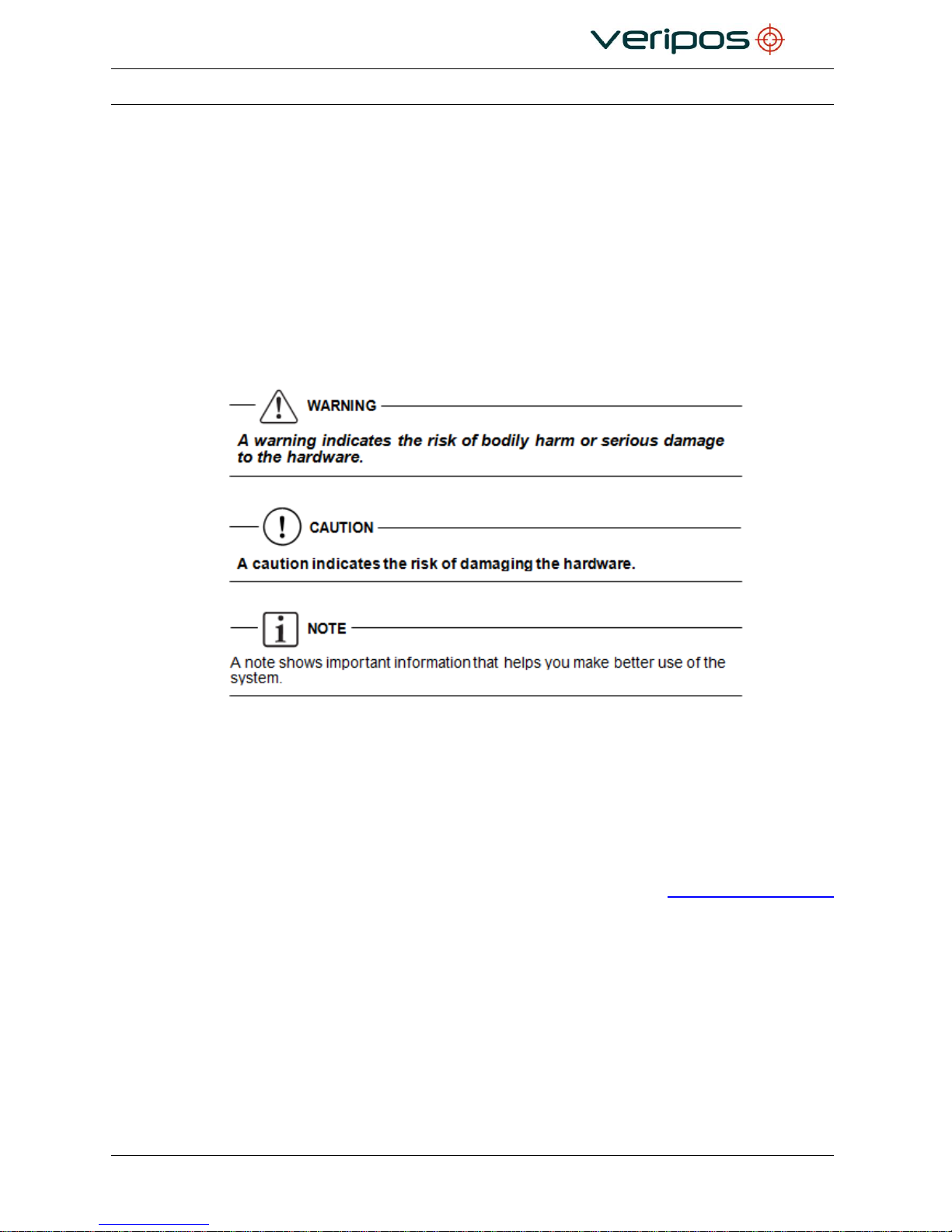
Italic or bold text is used to emph asize certain parts of the information. Italic
is also used in
cross-references to other parts of the document.
Bold text is also used for indicators and touch screen “push-buttons”
commands.
“Text within quotes” is used when display screens are mentioned in text.
Monospace
text is used for input/output strings to/from the device.
1.6.2 Special Notices
1.7 REFERENCES
Please read this manual and refer to the following information where required:
VERIPOS document “Antenna & Coaxial Cable Installation”.
LD7 Operations manual and Quick Guide.
Information is available at VERIPOS Online support system (VOSS): http://help.veripos.com
Page 13

Procedure Title:
LD7 Installation Manual
File Ref.:
AB-V-MA-00559
Rev No:
A7
Page 13
1.8 WASTE ELECTRICAL AND ELECTRONIC EQUIPMENT
The Waste Electrical and Electronic Equipment Directive (hereinafter referred to as the “WEEE
directive”) places an obligation on EU-based manufacturers, distributors, retailers and
importers to take back electronic products at the end of their useful life. A sister directive,
RoHS (Restriction of Hazardous Substances) complements the WEEE directive by banning the
presence of specific hazardous substances in the products at the design phase. The WEEE
directive covers all VERIPOS products imported into the EU as of August 13 2005. EU-based
manufacturers, distributors, retailers and importers are obliged to finance the costs of recovery
from municipal collection points, reuse, and recycling of specified percentages per the
requirements contained in the WEEE Directive.
Instructions for disposal of WEEE by users in the European Union.
Products which have the undernoted symbol located on either the product itself or its
packaging indicates that the product must not be disposed of with other waste. Instead, it is the
user’s responsibility to dispose of the product by handing it over to a designated collection point
for the recycling of WEEE.
The separate collection and recycling of your WEEE at the time of disposal will help to
conserve natural resources and ensure that it is recycled in a manner that protects human
health and the environment. For more information about recycling centres, please contact the
local city office, the household waste disposal service or the product supplier.
Page 14

Procedure Title:
LD7 Installation Manual
File Ref.:
AB-V-MA-00559
Rev No:
A7
Page 14
1.9 DISCLAIMER
Veripos Limited (hereinafter referred to as “Veripos”) has taken every care in the preparation of
the content of this Manual (“Manual”). This Manual is provided “as is” without any
representations or warranties, express or implied. Veripos makes no representations or
warranties in relation to this Manual and the content provided herein. Veripos reserves the right
at its sole discretion, but without any obligation, to make amendments or improvements to, or
withdraw or correct any error(s) or omission(s) in any portion of the Manual without notice.
Although Veripos makes a reasonable effort to include accurate and up to date information,
Veripos does not warrant or guarantee that this Manual and its contents are current, complete,
accurate and/or free from errors.
Copyright © 2004-2017 VERIPOS
All rights reserved. No part of this Manual and its contents may be reproduced, copied, reengineered, adapted, redistributed, published, commercially exploited or transmitted in any
form, by any means, electronic or mechanical, including photocopying or recording, without
the express prior written permission of Veripos. Applications for any written permission
should be addressed to Veripos House, 1B Farburn Terrace, Dyce, Aberdeen, AB21 7DT,
United Kingdom.
Unauthorised reproduction, copying, re-engineering, adaption, redistribution, publication or
commercial exploitation of this Manual or its contents may be subject to civil as well as
criminal sanctions under the applicable laws. Where Veripos’ intellectual property rights are
alleged to be infringed by the end user, Veripos will seek to enforce its intellectual property
rights in the civil courts to the fullest extent possible. Where reproduction, copying, reengineering, adaption, redistribution, publication or commercial exploitation of this Manual or
its contents has been permitted by Veripos in accordance with this disclaimer, then no
changes in the Manual or deletion of any kind to the Manual will be made by end user. End
user acknowledges that it does not acquire any ownership rights by accessing, viewing or
utilising this Manual and agrees that it shall not hold itself out to any third party as having any
ownership rights to this Manual.
The end user shall save, indemnify, defend and hold Veripos harmless on written demand,
from all claims, losses, damages, costs (including legal costs), expenses and liabilities of any
kind and nature, invoked against Veripos by any third party, for or arising out of, any alleged
infringement of any patent or proprietary or protected right arising out of or in connection with
the utilisation of this Manual by the end user and/or in connection with any representation to
third parties of ownership of any kind with respect to this Manual by the end user.
Page 15

Procedure Title:
LD7 Installation Manual
File Ref.:
AB-V-MA-00559
Rev No:
A7
Page 15
To the fullest extent permitted by applicable laws, Veripos hereby excludes liability, for any
damages, direct or indirect, punitive, incidental, special, consequential or other damages
arising out of or in any way connected with the use of, reference to, reliance on or inability to
use this Manual and its contents, including without limitation, any loss of profits, business
interruption or damage. These limitations shall apply even if Veripos has been expressly
advised of the potential loss.
This disclaimer and the exclusions herein shall be governed by and construed in accordance
with English law. If any provision of this disclaimer and/or exclusions are held to be unlawful,
void or for any reason whatsoever, unenforceable, then that provision shall be deemed
severable and shall not affect the validity and enforceability of the remaining provisions of this
disclaimer.
Page 16

Procedure Title:
LD7 Installation Manual
File Ref.:
AB-V-MA-00559
Rev No:
A7
Page 16
2. LD7 SYSTEM DESCRIPTION
This section gives an outline description of the VERIPOS LD7 receiver and
components used with the LD7 supplied.
The section covers overall information and details as follows:
Equipment technical data
Mechanical dimensions
Electrical specification
Processor
GNSS Receiver
L-Band Receiver
Data interfaces including serial ports
Antennas
2.1 LD7 RECEIVER
The VERIPOS LD7 is a small, leightweight and economical unit which may be configured as an
Integrated Mobile Unit, complete with internal dual L1/L2 GPS and GLONASS receiver.
The unit incorporates front panel LED indicators for status monitoring. Configuration is
performed using an external PC running the recommmended Web interface browser (Google
Chrome).
For maximum flexibility, the design includes dual frequency Heading capability and all tiers of
VERIPOS positioning accuaracy.
It can receive VERIPOS L-Band transmissions from Geostationary satellites and output RTCM
correction data which may be used by external equipment. The LD7’s internal dual-frequency
GNSS receiver can be used with Verify QC software to provide the full range of VERIPOS
GNSS augmentation services.
The unit can compute DGNSS position solutions using single or multiple reference stations.
When subscribed to VERIPOS PPP corrections the unit is capable of computing position
solutions with 10cm accuracy. Positions are output in NMEA format for use by the user’s
systems.
At the same time the GNSS engine can be used to compute a baseline between the 2 antennas
installed and generate a heading value output in NMEA format.
Page 17
Procedure Title:
LD7 Installation Manual
File Ref.:
AB-V-MA-00559
Rev No:
A7
Page 17
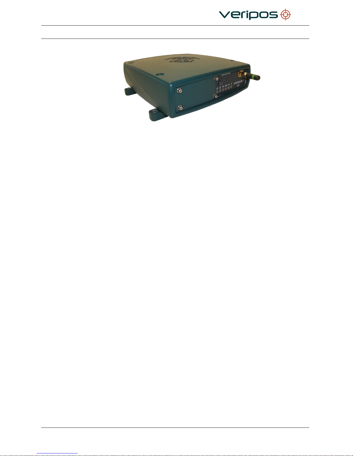
The VERIPOS LD7 Receiver
LD7 comprises:
• L-Band receiver
• GNSS Heading receiver
• Interfaces for data output
2.1.1 Installation
Installation work for the LD7 varies for:
• the types of antenna(s) to be installed
• connections for input of data to or output of positioning data from the LD7.
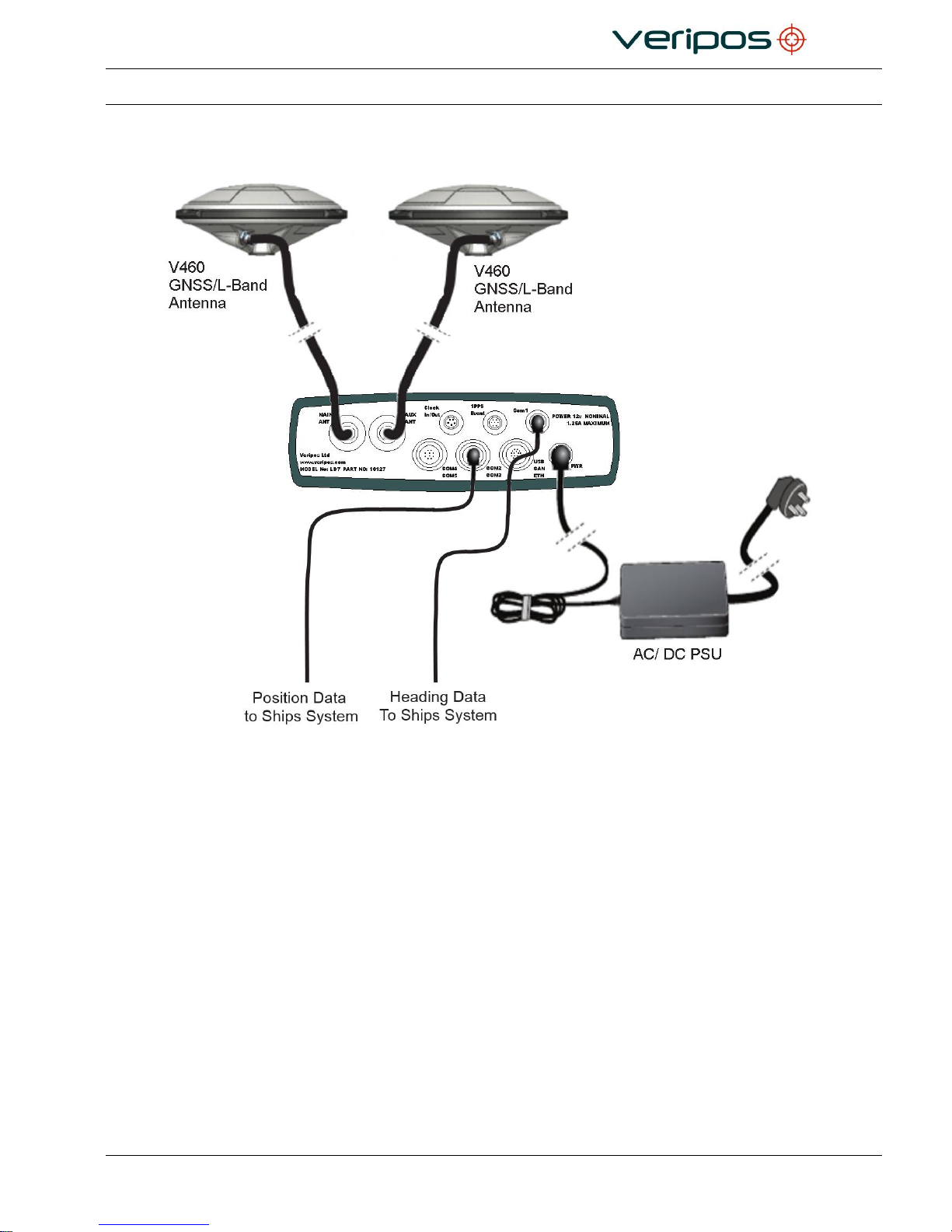
Installation is described in detail in chapter 3 Installation. An example is
shown below to illustrate arrangement of a typical installation of antennas
and position output from the LD7
Page 18
Procedure Title:
LD7 Installation Manual
File Ref.:
AB-V-MA-00559
Rev No:
A7
Page 18
2.1.2 LD7 installation – Schematic example
Example of an Installation Drawing for an LD7
Page 19
Procedure Title:
LD7 Installation Manual
File Ref.:
AB-V-MA-00559
Rev No:
A7
Page 19
2.2 TECHNICAL SPECIFICATIONS
This equipment is for indoor use only and meets performance specification
within an ambient temperature range of -15 °C to +55 °C and a maximum
relative humidity of 95%.
Equipment complies with EN60945:2002 [5] for “protected” equipment.
Cable specifications: Please refer to the Reference information chapter for
details.
The LD7 is sealed to the IP67 specification.
LD7 Overview
2.2.1
Mechanical
Dimensions
Height
54 mm
Width
157 mm
Depth
164 mm
Weight
1.5 kg
2.2.2
Environmental
Enclosure material
Aluminium
Operating temperature range
-30 °C to +65 °C
Storage temperature range
-40 °C to +75 °C
2.2.3 Safety considerations
Though the test conditions for the LD7 unit provide for a max. operating
temperature of +65 °C, continuous operation of all electronic components
should if possible take place at ambient temperatures of only +25 °C. This is
a prerequisite for long life and low service costs.
Page 20
Procedure Title:
LD7 Installation Manual
File Ref.:
AB-V-MA-00559
Rev No:
A7
Page 20
2.2.4
Electrical
DC power input
12–24 VDC
Power consumption -
<12 W
IEC60945
certified
2.2.5
Certification
Conforms to IP67, RoHS, CE, FCC Class B Part 15, IEC 60945.
2.2.6
Connectors and I/O ports
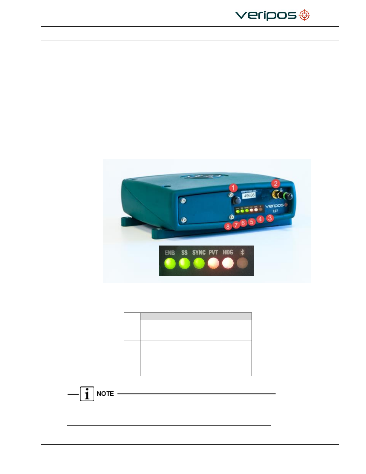
The controls etc. are detailed in this chapter
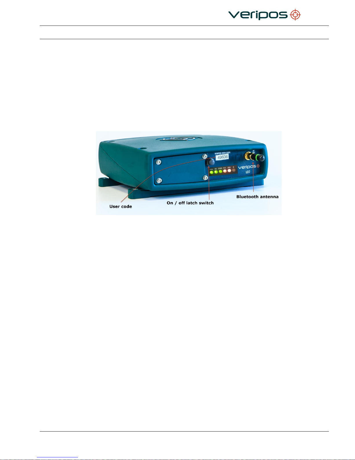
LD7 Front Panel
Description
1
Power Button
2
Bluetooth Antenna Connector
3
Bluetooth LED
4
HDG (Heading) LED
5
PVT (Accuracy) LED
6
SYNC (Beam) LED
7
SS (Signal Strength) LED
8
ENB (Enabled)LED
There is no Bluetooth functionality current available on the LD7.
Page 21
Procedure Title:
LD7 Installation Manual
File Ref.:
AB-V-MA-00559
Rev No:
A7
Page 21
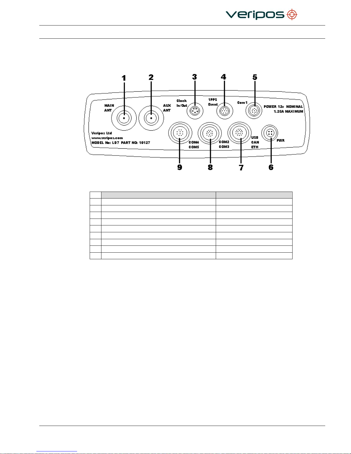
2.2.7 Rear panel
LD7 Rear Panel
Description
Connector Type
1
Main Antenna Connector
TNC
2
Aux Antenna Connector
TNC
3
Clock In/ Out Connector*
Lemo 5-Pin
4
‘1PPS’ / Event Output BNC connector*
Lemo 7-Pin
5
COM1 Serial Connector*
Lemo 9-Pin
6
Power Connector*
Lemo 4-Pin
7
USB / Ethernet connector*
Lemo 16-Pin
8
COM2 / COM3 Serial Connector*
Lemo 14-Pin
9
COM4 / COM5 Serial Connector*
Lemo 10-Pin
* Interface cables are supplied to convert connectors to DB9 for interfacing to vessel systems.
Page 22
Procedure Title:
LD7 Installation Manual
File Ref.:
AB-V-MA-00559
Rev No:
A7
Page 22
2.2.8 Serial ports
Serial ports:
5 bidirectional
Format :
RS232
Interface type:
DB9
See the Installation chapter for details of data streams.
Not all data streams are compatible with all baud rates.
2.2.9 Ethernet Interfaces
An Ethernet RJ45 LAN port is fitted on the rear panel.
The LD7 has a default fixed IP address: 192.168.0.126
The GNSS card has a default fixed IP address: 192.168.0.127
The L-Band card has a default fixed IP address: 192.168.0.128
The Ethernet port can be connected for communication to a PC or Ethernet router. This is
internally connected to an Ethernet hub to communicate with the internal processor or the
GNSS receiver.
The LD7 IP address is used only to access the Web Interface page. Data outputs via
Ethernet can be obtained using the GNSS and L-Band card IP addresses.
2.2.10 USB Ports
The USB is most commonly used to check the LD7 IP address if the event that it is not
known or have been forgotten. Steps for checking the LD7 IP address are detailed in the
LD7 Operations Manual.
2.2.11 Power Supply
LD7 requires a 9 - 30V DC supply and is supplied with an external 110/240V AC power
unit.
Page 23
Procedure Title:
LD7 Installation Manual
File Ref.:
AB-V-MA-00559
Rev No:
A7
Page 23
2.2.12 Summary Specification of Antennas
2.2.12.1 V460
L-Band/GPS/Glonass:
1525-1610 MHz
GPS L2/Glonass L2:
1160-1252 MHz
Fitted with a Narrow band filter for interference rejection
LNA Gain:
45db
DC Voltage input:
3.0 to 15.0V
RF Input Connector:
TNC Socket
Material:
Weather Proof Polymer Plastic
Mount:
5/8” Tripod Tread Connector
Temperature Range:
-55 to +85°C
Certification:
IEC 60945
Diameter:
7.5“ / 19.05cm
Height:
3.17” / 8.05cm
Weight:
1.6lbs / 0.73kg
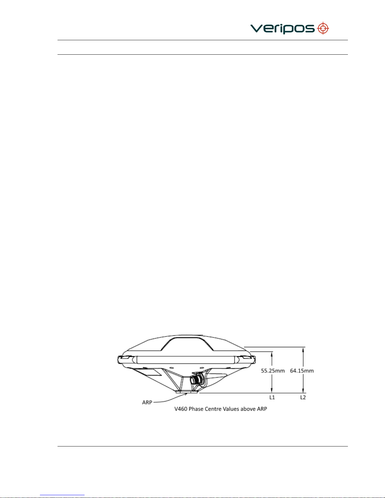
2.2.12.2 V460 Phase Centre Offsets
The diagram below shows the antenna reference point (ARP) from which the phase centre
values are measured. It also shows the V460 vertical (Up) phase centre values for the
GNSS L1 and L2 frequencies:
Page 24
Procedure Title:
LD7 Installation Manual
File Ref.:
AB-V-MA-00559
Rev No:
A7
Page 24
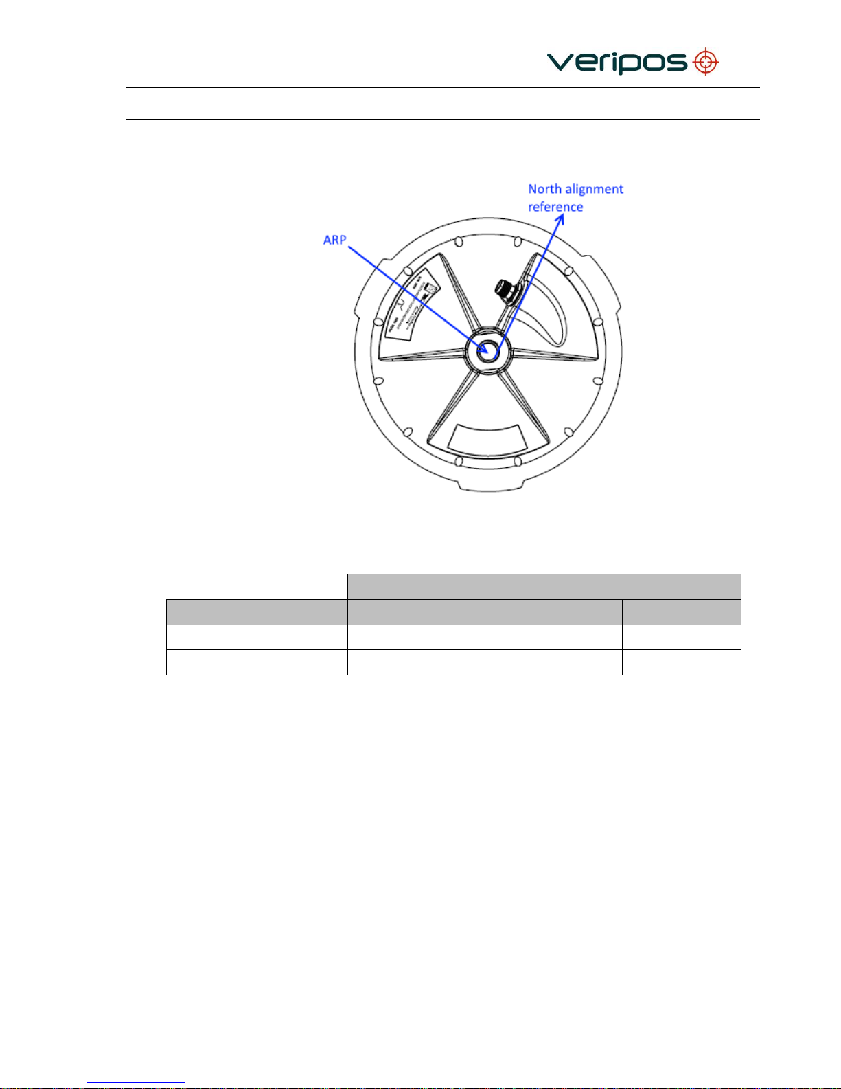
The below diagram shows the ARP at the antenna base and the antenna North alignment
reference:
V460 ARP & North Alignment Reference
The table below details the North, East and Up phase centre values for the GNSS L1 and
L2 frequencies:
Relative to Antenna Reference Point (ARP)
GNSS Frequency
North (mm)
East (mm)
Up (mm)
L1
2.78
-1.27
55.25
L2
0.82
-1.09
64.15
2.2.13 Antenna cables – Specifications
Typically VERIPOS provide with the system pre-terminated cables and tails
for use with both L-band and GNSS/GPS antennas (see the ‘Equipment
Packing List’).
VERIPOS recommend use of Times Microwave coaxial LMR cable for
installation of all antennas. See the Reference information chapter for details.
2.2.14 GNSS Receiver
The GNSS receiver for the LD7 receives GPS broadcast information.
Page 25

Procedure Title:
LD7 Installation Manual
File Ref.:
AB-V-MA-00559
Rev No:
A7
Page 25
2.2.14.1 GNSS Module AsteRx2eH
Product features:
Channels
272
GPS
L1/L2/L2C
GLONASS
L1/L2
SBAS
WAAS, EGNOS, MSAS
Accuracy
GNSS Heading
0.03 deg @ 10m separation
0.1 deg @ 3m separation
0.3 deg @ 1m separation
DGPS
Refer to VERIPOS Spec sheets
PPP
Refer to VERIPOS Spec sheets
Static
5 mm + 0.5 ppm Vertical
5 mm + 0.5 ppm Vertical
Measurement Rate
100 Hz
Latency
<20 msec
Average Time to Fixed RTK
<7 sec
Cold Start
<45 sec
Warm Start
<20 sec
Re-acquisition
<1.2 sec
Input / Output
1PPS
2 x Event Marks Ref In/Out
RTCM2.x, RTCM3.x,
CMR, CMR+
NMEA 0183 V2.30 (*5 Hz max)
*The default data output rate on an LD7 is 1Hz. Contact VERIPOS for guidance if 5Hz outputs are
required.
Page 26

Procedure Title:
LD7 Installation Manual
File Ref.:
AB-V-MA-00559
Rev No:
A7
Page 26
3. INSTALLATION
This section provides guidance on the installation of the LD7 receiver.
Contact your supplier or VERIPOS with questions or for advice when installing this
equipment.
3.1 LD7 SITING GUIDELINES
When choosing a location for the LD7 and variants the following requirements are
mandatory:
1. Ensure adequate ventilation for free air flow to the unit. This is important when working
in hot or humid regions.
2. Locate unit in areas free from excessive dust or smoke.
3. Avoid locations that experience excessive vibration.
4. Avoid exposure to high temperatures.
5. Shield the unit from direct sunlight.
6. Mount the unit securely to prevent movement.
7. Ensure there is easy access to front panel.
8. Ensure adequate access to the rear panel. Avoid mounting in a recess and have
sufficient slack to be left in cables (power, interfacing and coaxial) for LD7 unit to be
removed without disconnection.
9. All bends in coaxial cables to be maintained above minimum bend radius.
10. Use short tails of flexible coaxial cable (e.g. LMR 240) with appropriate converter
connections to connect antenna coaxial cables to the LD7. Support the antenna
coaxial cable weight to avoid stress being placed on the rear coaxial connectors.
3.1.1 Mounting
The LD7 is supplied with mounting brackets. These can be fitted to the top or bottom of the
receiver. This allows the receiver to be fixed to the top or underside of a shelf.
Page 27
Procedure Title:
LD7 Installation Manual
File Ref.:
AB-V-MA-00559
Rev No:
A7
Page 27
3.1.2 Ventilation Requirements
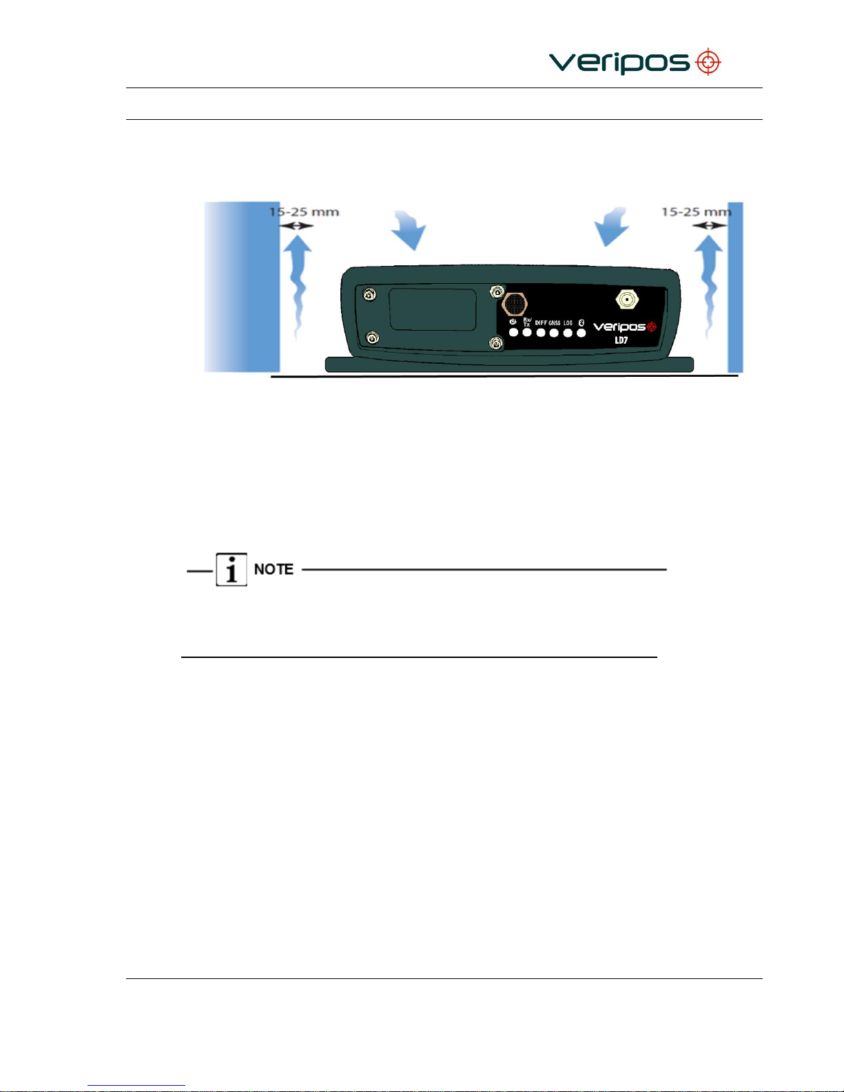
The LD7 needs 15–25 mm minimum clearance all round, to allow a flow of air.
LD7 Ventilation
3.2 ANTENNA INSTALLATION
This section provides general guidance on installation of antennas and cabling when
installing the LD7 receiver.
It is very important to the on-going performance of your system that a high quality
installation is performed. This will ensure optimum performance and reliability.
After equipment installation it is recommended that a calibration survey is carried out to
compute any heading C-O and GNSS offsets for the Main GNSS antenna. Antenna offsets
and C-O values should be entered within the navigation or DP software.
3.2.1 GNSS / L -Band Antenna
The GNSS / L-Band antenna receives transmissions from GPS, GLONASS and L-Band
communication satellites (used for VERIPOS Correction Signals).
This section describes best practice when positioning and installing your GNSS / L-Band
antennas.
For more details please refer to VERIPOS document “Antenna & Coaxial Cable Installation
Guide” provided as part of the installation documentation.
Page 28
Procedure Title:
LD7 Installation Manual
File Ref.:
AB-V-MA-00559
Rev No:
A7
Page 28
3.2.1.1 General
The GNSS/ L-Band antenna is used for vessel positioning and therefore its mounting
location is of high importance to the system.
It should be mounted with a clear view of the sky in both the horizontal and vertical
directions.
If the antenna does not have a full view of the sky there will be times when signals will be
blocked, resulting in degraded performance of the system.
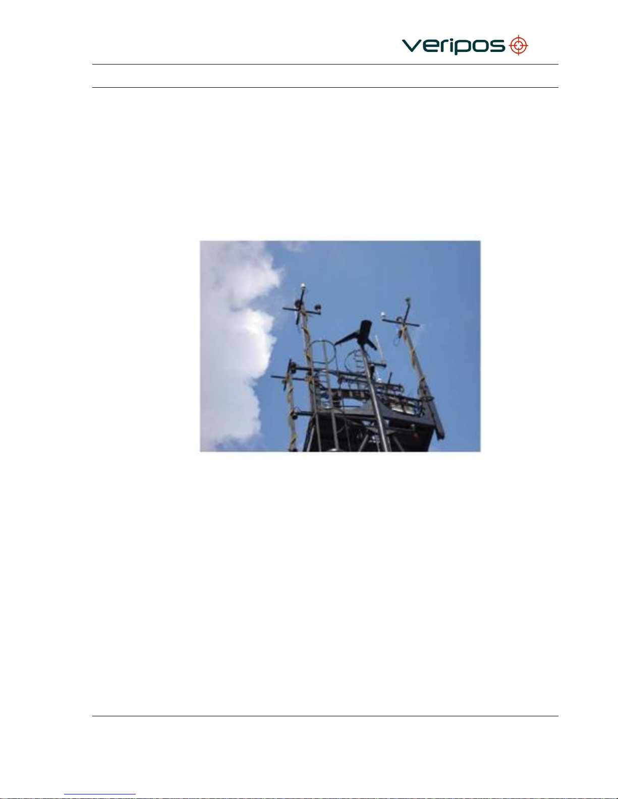
Good Installation – Antenna at Top of Mast with Good Spacing
During installation observe the following guidelines:
Offsets to the GPS antennas must be measured by a competent person to ensure no
errors are introduced to the DP, Survey or Navigation systems.
Care must be taken to ensure that antennas are not installed in the direct path of
Radar transmissions, Inmarsat-B Dome transmissions, VSAT transmissions or high
power HF whip/wire antenna.
Page 29
Procedure Title:
LD7 Installation Manual
File Ref.:
AB-V-MA-00559
Rev No:
A7
Page 29
Good Installation – Antenna at Top of Mast with Good Spacing
If antennas cannot be installed directly at the top of the mast/ships structure, it is essential
that the mounting point is sufficiently strong for this purpose. Arrangements must be able to
withstand vibration and wind.
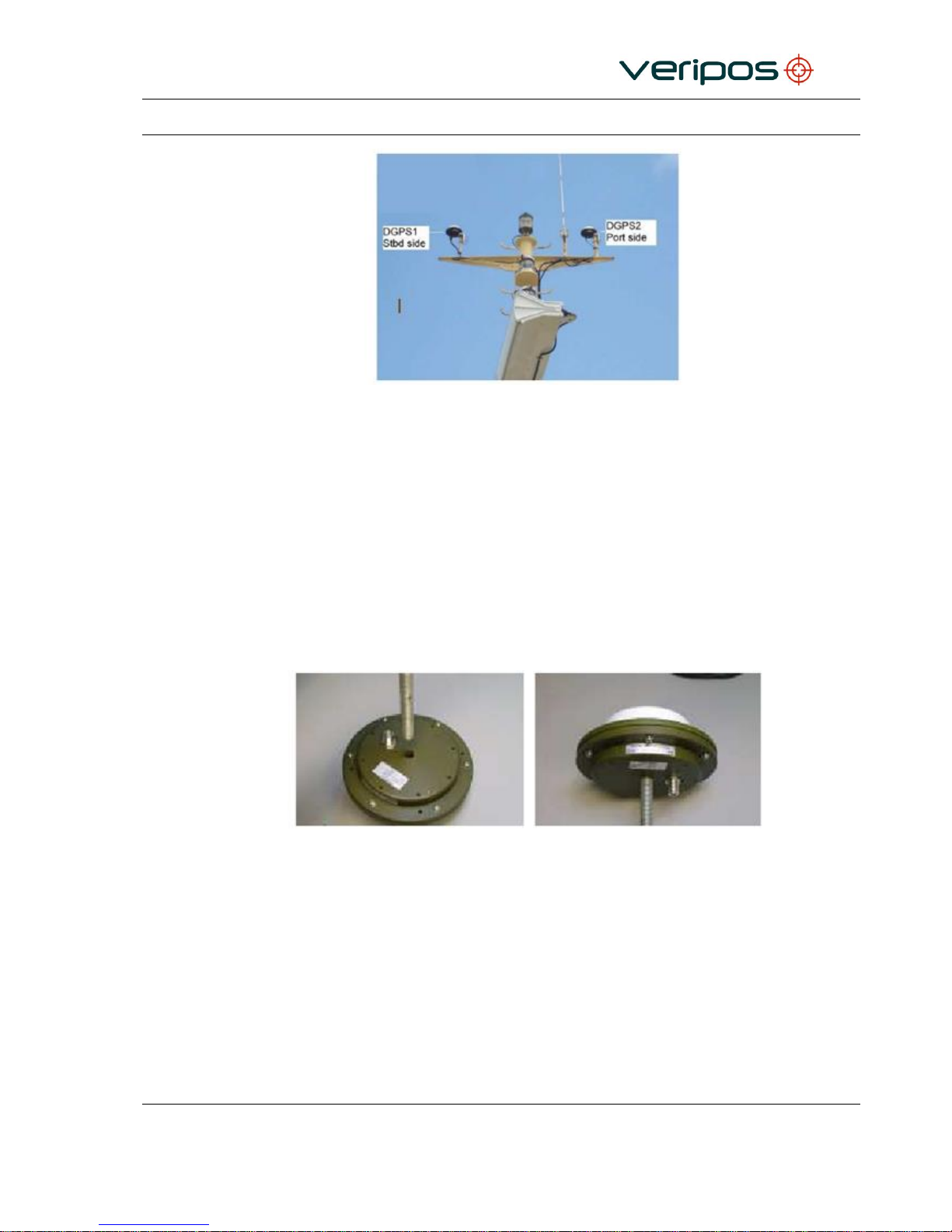
Alternatively a pole can be used with a 5/8"x11 UNC threaded end (standard marine
mount). The pole can be attached by welding or using “U” clamps as above. This method
allows the GNSS/GPS antenna to be mounted without the need for the bracket. Ensure that
grease is applied to the threads when installing the antenna.
Fit the antenna to the bracket and clamp the bracket to the mounting pole or the mast using
“U”-bolts. When mounting the antenna on an extension pole fit the antenna to the pole first
for ease of handling at height.
Antenna with extension pole
If the threaded pole is already installed up the mast, use a small length of coaxial cable
attached to the N-type connector as a safety lanyard for the antenna.
Carefully connect the coaxial cable following manufacturers’ guidelines.
Form cable below the antenna into a small loop, approximately 150–220 mm (6 to 8in) in
diameter. Attach the loop to the mounting pole under the antenna to provide strain relief
from the cable.
For more detailed guidance please refer to the VERIPOS document “Antenna and Coaxial
Cable Installation Guide”.
Page 30
Procedure Title:
LD7 Installation Manual
File Ref.:
AB-V-MA-00559
Rev No:
A7
Page 30
3.2.2 Antenna Placement for GNSS Heading
Careful consideration of the placement of the Main and Auxiliary antennas is required to
maximise the LD7’s GNSS headlining accuracy.
3.2.2.1 Antenna Separation
The GNSS heading solution accuracy is largely determined by the distance (or baseline)
between the Main and Auxiliary antennas. The larger the baseline, the better the heading
precision will be.
The table below details the expected GNSS heading precision in relation to the baseline:
Baseline
GNSS Heading Precision
1m
0.3°
3m
0.1°
10m
0.03°
VERIPOS recommend a minimum baseline of 2m.
3.2.2.2 Antenna Orientation & Height
The LD7 GNSS heading is computed from the Main to the Auxiliary antenna as illustrated
below:
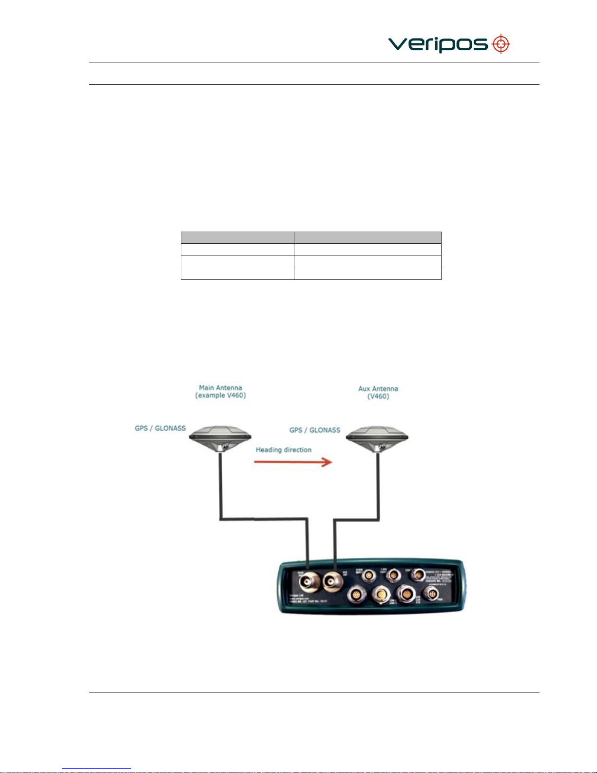
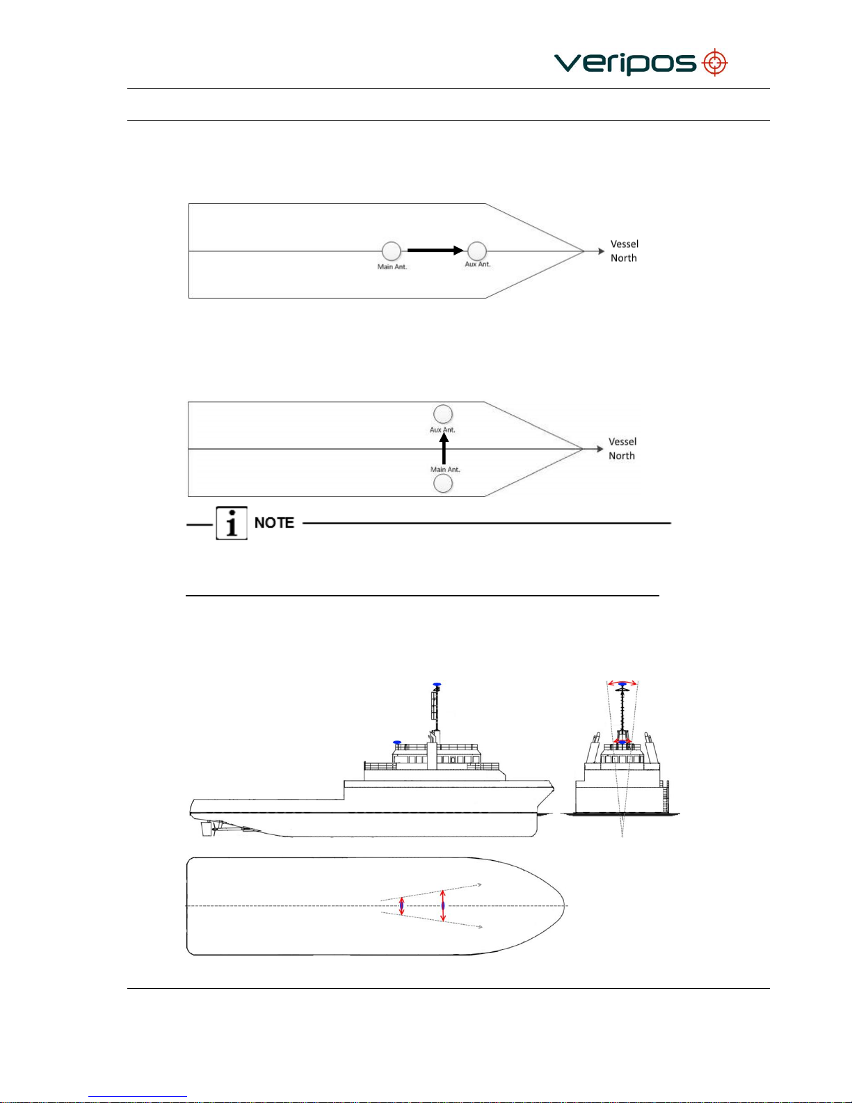
GNSS Heading Solution Direction
Page 31
Procedure Title:
LD7 Installation Manual
File Ref.:
AB-V-MA-00559
Rev No:
A7
Page 31
Assuming the antennas are mounted along the vessel Fwd/Aft centreline, with the Aux
being the furthest forward antenna, the GNSS heading would correctly reflect the vessel’s
heading. In the below example, no heading correction would need to be applied in the
navigation system software:
In the next example, the Main and Auxiliary antennas are installed perpendicular to vessel
North with the Main antenna at the Starboard side and the Auxiliary antenna at the Port
side. A correction (C-O) of +90° would be required in the navigation system software to
align the GNSS heading to vessel North.
The above examples are simplified for illustration purposes. To achieve the heading
accuracies specified a gyro calibration should be conducted.
The Main and Auxiliary antenna should also be installed at similar heights to ensure
consistent heading. If this is not done the heading solution will be noisy due to each
antenna being subject to different amounts of vessel motion e.g. vessel roll.
Vessel motion when antennas mounted at different heights
Page 32
Procedure Title:
LD7 Installation Manual
File Ref.:
AB-V-MA-00559
Rev No:
A7
Page 32
3.3 COAXIAL CABLE INSTALLATION
VERIPOS recommend and supply pre-terminated LMR coaxial cables as they give the best
performance in permanent installations.
Label each cable carefully at top and bottom identifying the antenna attached.
3.3.1 Maximum recommended cable lengths
The signals received by the antennas will deteriorate at different rates as they are
transmitted through coaxial cable. As a result VERIPOS recommend a maximum cable
length.
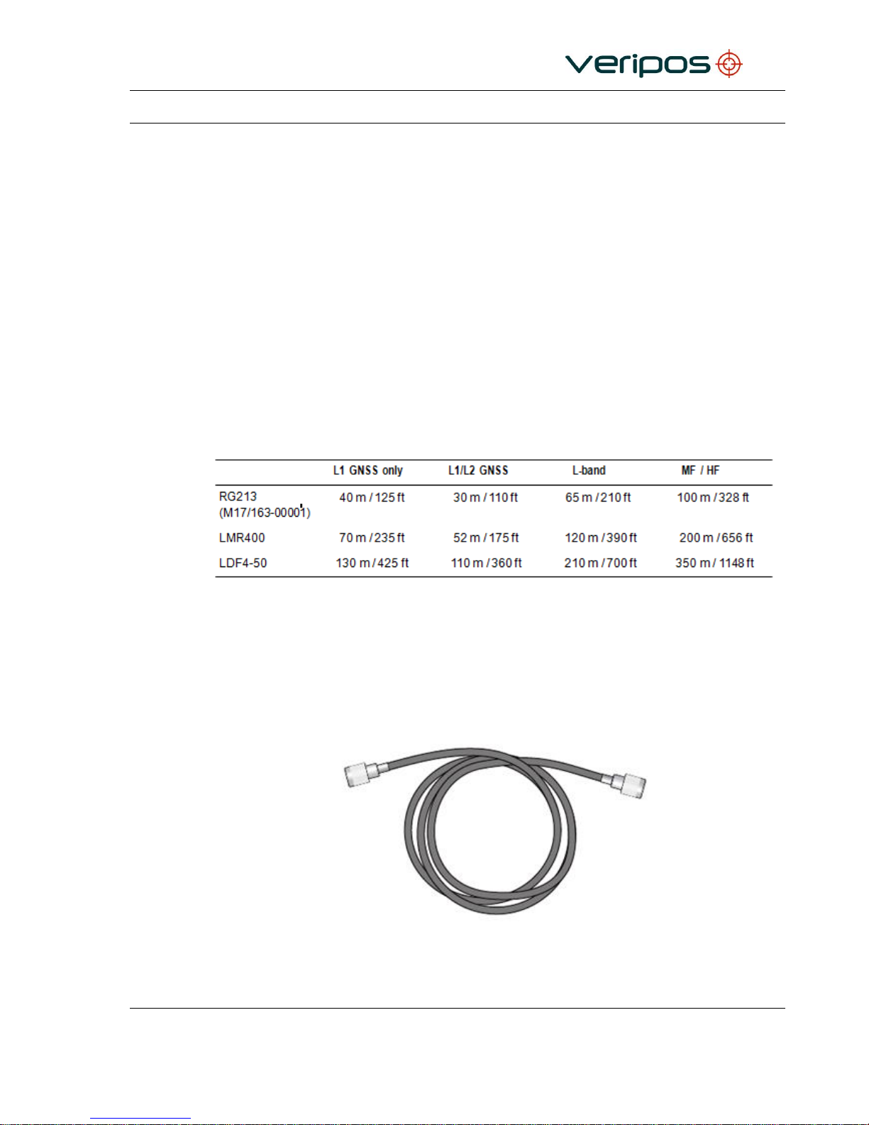
The following table details the maximum length for each signal type.
3.3.2 General
VERIPOS recommended cable for the antenna runs is LMR 400.
Terminated tails of LMR 240 are used at either end for ease of attachment to hardware.
Terminated Tails of LMR240
Page 33
Procedure Title:
LD7 Installation Manual
File Ref.:
AB-V-MA-00559
Rev No:
A7
Page 33
When running multiple coaxial cables VERIPOS recommend labelling to ensure cables are
attached to the correct antennas and equipment.
Survey the route of the antenna cabling to ensure:
1. The total length of the cable run does not exceed the supplied cable length for this
installation. Contact your supplier or VERIPOS if this is the case.
2. The cable does not cross or run parallel with any single phase or three phase mains
cable (110 VAC, 220 VAC or 440 VAC) or any high power RF cables leading to
transmitting devices such as Inmarsat B and VSAT domes.
3. The cable avoids fluorescent lights.
4. A support wire is used where the cable run has to cross a free space and does not
rely solely on cable ties for support.
5. Sufficient space is available in the selected cable entry through the bulk head for the
connectors to pass through without damage. If the connector cannot pass through the
cable entry it may be necessary to cut the connector off and re-terminate once the cable
has been passed through.
6. The cable is not pinched.
7. The route is free from all burrs or sharp edges that could damage the cable jacket.
8. All connectors and couplers are properly sealed from the environment with self-
amalgamating tape and electrical tape.
9. Stress loops are fitted to prevent excess force on the connectors, in particular the
antenna connectors.
10. The minimum bend radius for the cable is not exceeded.
Once cables are in place seal all connections with self-amalgamating tape for
protection against the marine environment.
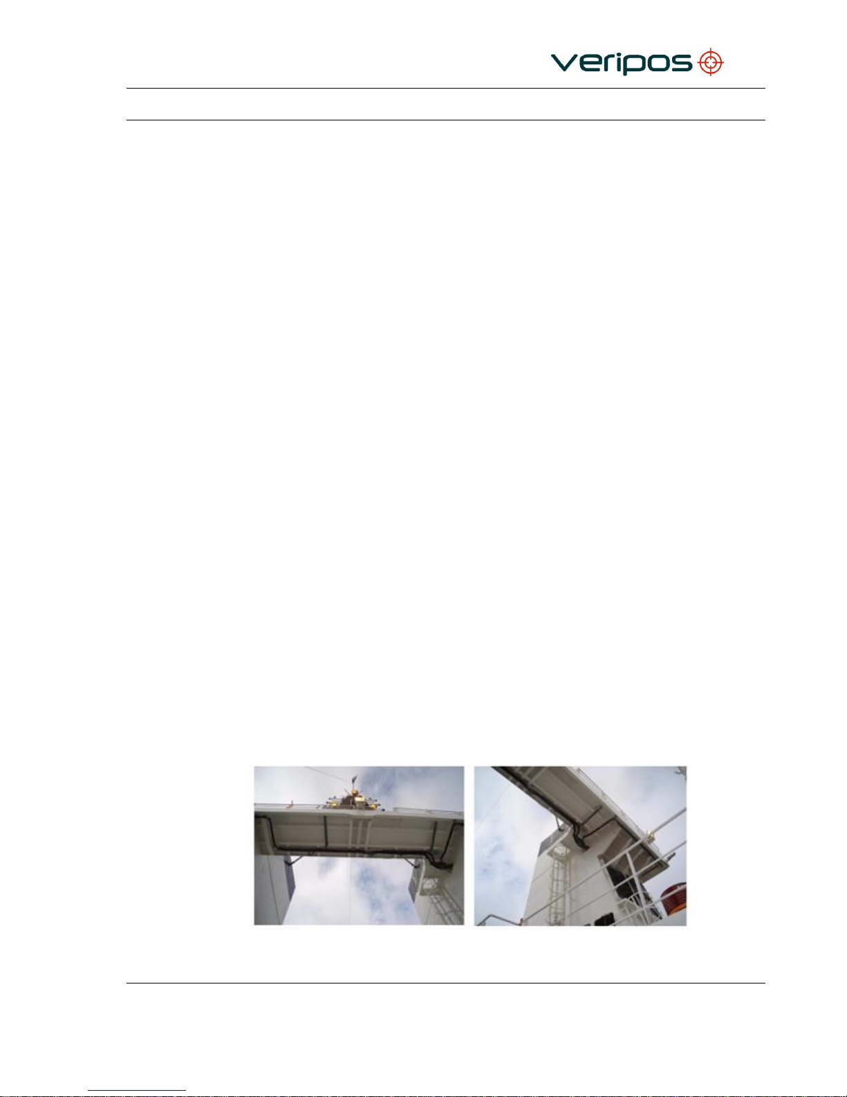
Typical Cable installation in Bridge Mast Area
Page 34
Procedure Title:
LD7 Installation Manual
File Ref.:
AB-V-MA-00559
Rev No:
A7
Page 34
3.4 LD7 ANTENNA CONNECTIVITY
This section details the antenna connections made to the LD7 IMU.
3.4.1 Coaxial cables to antennas
3.4.1.1 Standard LD7 Variant
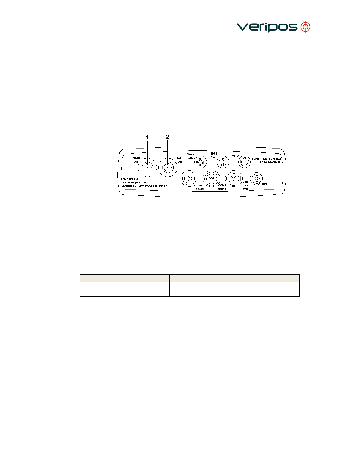
Two antenna connections (Main and Auxiliary) are required to obtain a GNSS heading
solution.
These are shown below;
LD7 Rear Panel Antenna Connections
If a GNSS heading solution is not required, the LD7 can provide VERIPOS position
solutions with just the Main antenna connection. On a standard LD7, the Main antenna
input is used as both a GNSS and L-Band correction input.
Key:
Connection Name
Function
Typical antenna
1
Main
L-Band, GNSS
V460
2
Aux
GNSS
V460
3.4.1.2 LD7 Mod 1 Variant – Dedicated L-Band Input
The LD7 can be supplied with a dedicated L-Band antenna input if required. This is useful
on installations where the optimum location for the GNSS antennas may not be the
optimum location for L-Band reception.
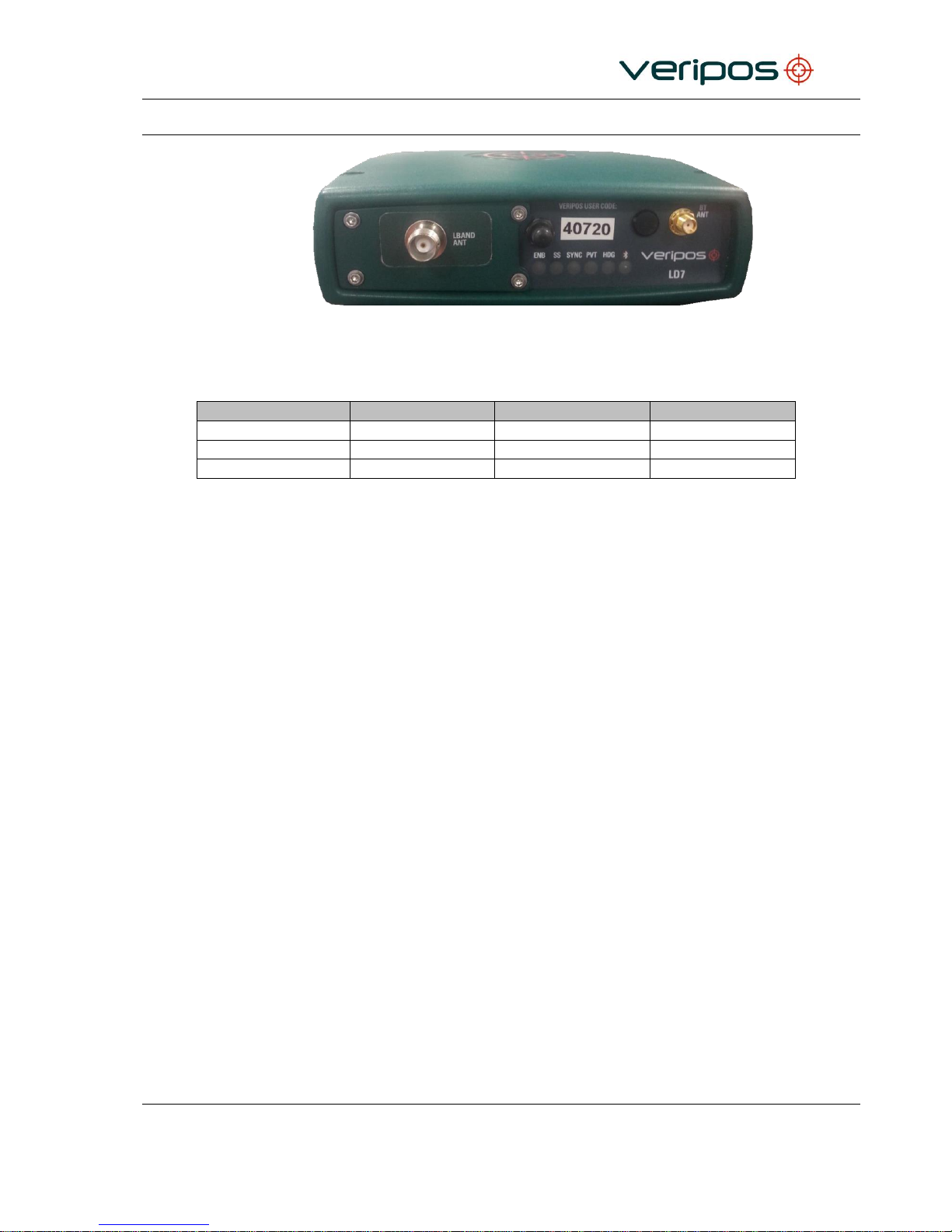
An LD7 Mod 1 unit will therefore have three antenna inputs. The Main antenna will be the
main GNSS input however will no longer be used for L-Band.
The function of the Auxiliary antenna input remains unchanged and is used a secondary
GNSS input for GNSS heading.
There will be a dedicated coaxial connector (TNC) installed on the front of the LD7 which
will be used only to receive L-Band correction data using a dedicated L-Band antenna e.g.
V86 antenna.
Page 35
Procedure Title:
LD7 Installation Manual
File Ref.:
AB-V-MA-00559
Rev No:
A7
Page 35
LD7 Mod 1 Unit with dedicated L-Band input
The table below shows the antenna connectors used on an LD7 Mod 1 IMU:
Connector Name
Connector Type
Function
Typical Antenna
Main
TNC
GNSS (Primary)
V460
Auxiliary
TNC
GNSS (Secondary)
V460
LBAND Ant
TNC
L-Band corrections
V86
Page 36
Procedure Title:
LD7 Installation Manual
File Ref.:
AB-V-MA-00559
Rev No:
A7
Page 36
3.5 LD7 POWER AND INTERFACE
This section details the power and interface cables connected to the LD7 IMU.
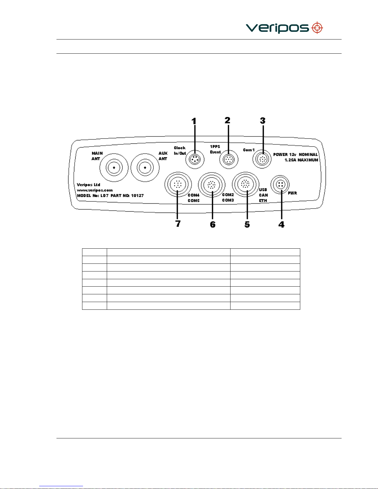
3.5.1 LD7 Rear connections
LD7 Rear Panel Power and Interface Connections
Label
Description
Connector Type
1
Clock In/ Out Connector
Lemo 5-Pin
2
‘1PPS’ / Event Output BNC connector
Lemo 7-Pin
3
COM1 Serial Connector
Lemo 9-Pin
4
Power Connector
Lemo 4-Pin
5
USB / Ethernet connector
Lemo 16-Pin
6
COM2 / COM3 Serial Connector
Lemo 14-Pin
7
COM4 / COM5 Serial Connector
Lemo 10-Pin
Page 37
Procedure Title:
LD7 Installation Manual
File Ref.:
AB-V-MA-00559
Rev No:
A7
Page 37
3.5.2 Interface cabling
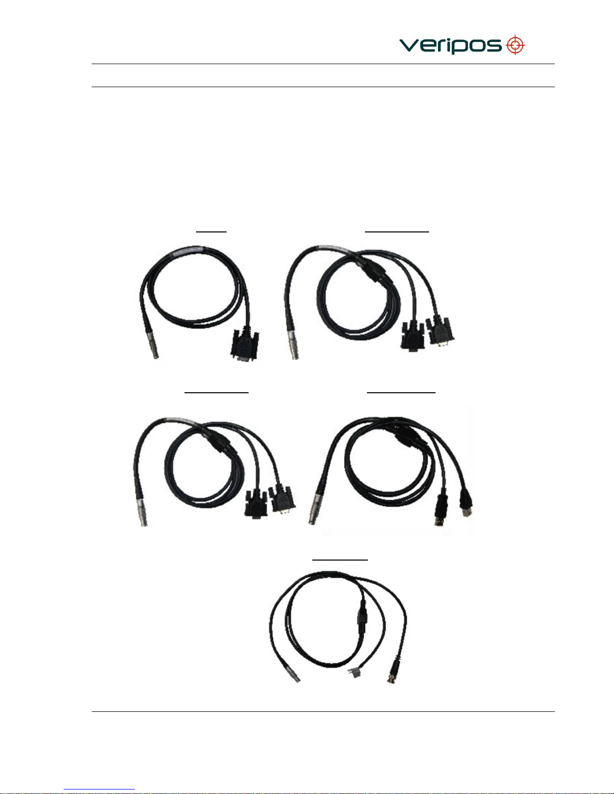
This section details the types of data cables connected to systems and used by systems on
the vessel.
Serial Data interface cables from the LD7 will use RS232 cables.
For Cable Pin-out details refer to the Reference Information Section of this manual.
Cables and adapters supplied:
Com 1 Com2 / Com3
Com4 / Com5 Ethernet / USB
PPS / Event
Page 38

Procedure Title:
LD7 Installation Manual
File Ref.:
AB-V-MA-00559
Rev No:
A7
Page 38
3.5.3 Serial Ports
LD7 has five RS-232 serial ports (COM 1–5) to make connections to ships system.
Com1: Direct communication with the internal processor.
Com2: Direct communication with the internal processor.
Com3: Direct communication with the GNSS Receiver.
Com4: Direct communication with the L-Band Demodulator.
Com5: Direct communication with the L-Band Demodulator.
For reference the LD7 default settings are shown below:
COM Port
Data String
Baud rate
Function
COM1
NMEA a
9600
8,N,1
NMEA data to vessel system Default
GGA Message
COM2
NMEA b
9600
8,N,1
NMEA data to vessel system Default
HDT Message
COM3
GNSS RAW
115200
8,N,1
Raw Data messages for use with Verify
QC
COM4
RTCM B
115200
8,N,1
VERIPOS Corrections for use with
Verify QC or standalone GNSS receiver
COM5
L-Band Control
115200
8,N,1
For use with VERIPOS L-Band Control
See the Reference information chapter for pin-out details and contact VERIPOS for advice
where required.
3.5.4 Ethernet interface
The LD7 is configured via Web Interface. The Ethernet RJ45 connector on the LD7 rear
panel can be connected directly to a PC with Ethernet port.
The default IP address used to access the Web Interface is 192.168.0.126. This can be
changed if required.
The Ethernet interface can also be used to output any data which is available via serial
port. When outputting data via Ethernet, the IP address and the data source must be used,
NOT the IP address of the LD7. For example, to output NMEA position or Heading data,
the GNSS card IP address must be used. To output RTCM correction data, the L-Band
card IP address must be used.
The default IP addresses are as follows:
LD7 default IP address: 192.168.0.126
GNSS card default IP address: 192.168.0.127
L-Band card default IP address: 192.168.0.128
Page 39

Procedure Title:
LD7 Installation Manual
File Ref.:
AB-V-MA-00559
Rev No:
A7
Page 39
The network ports for the data streams available on the LD7 are:
Data Stream
Port
RTCMa
9001
RTCMb
9002
L-Band Config
9003
NMEAa
9011
NMEAb
9012
Raw GNSS
9013
3.5.5 PPS/ Event/ Clock In/Out
The LD7 has a rear connector for output of a 1PPS (one pulse per second) signal, used by
external equipment for accurate time synchronisation to navigation systems or multi-beam
sonar. Output voltage is 3.3V.
This can be configured using Septentrio RX Control.
Event and Clock In/ out are not currently used.
3.5.6 Power and cabling
This section details the type and typical source for power supply to the LD7.
VERIPOS recommend using supplied external AC/DC Power supply unit.
Details and power source specification available from VERIPOS.
Power requirement of the LD7:
Input Voltage: 12 – 24 VDC
Power consumption: <12W.
The LD7 unit can alternatively be attached to the vessel DC supply.
The unit should be connected to a clean supply, e.g. UPS system.
Contact the Veripos Helpdesk if you need advice on supply of power to the LD7.
Page 40

Procedure Title:
LD7 Installation Manual
File Ref.:
AB-V-MA-00559
Rev No:
A7
Page 40
4. REFERENCE INFORMATION
4.1 CABLING AND CONNECTORS
This section contains details on the Interface and power connector pin assignments for the
LD7 IMU. It also details the termination procedure for LMR400 Coaxial cabling.
VERIPOS recommend that prefabricated main cables and coaxial tails are used for
connection of antenna to the VERIPOS below decks equipment.
4.1.1 Power Cable Pinout Details
The external power input is via the 4--‐pin LEMO connector.
LD7
Description
Cable Colour
4 Pin Lemo Pin
1
Power +
Red
4
Gound -
Black
4.1.2 Com1 Cable Pinout Details
This port uses cable assembly p/n 10120 which has 9--‐Pin Lemo plug to the LD7 rear
panel and a DB9 connector for RS--‐232 communication with COM1 of the system; direct
communication with the internal processor.
LD7
Description
Cable End Connector
9 Pin Lemo Pin
Com1 9 D-Type
1
CTS 8 6
RX
3
7
TX
2
8
RTS 7 9
Ground
5
4.1.3 Com2/ Com3 Cable Pinout Details
This port uses cable assembly p/n 10121, which has a Lemo 14--‐Pin plug that splits into 2
DB9 connectors for RS--‐ 232 communication with Com2 and Com3 of the system.
LD7
Description
Cable End Connector
14 Pin Lemo Pin
Com2 (9pin D-Type)
Com3 (9Pin D-Type)
5
RX 3 2
6
TX 3 3
7
RTS 2 8 8 TX 2 3
9
CTS 2 7
10
RX 2 2
11. 12, 13, 14
Ground 5 5
Page 41

Procedure Title:
LD7 Installation Manual
File Ref.:
AB-V-MA-00559
Rev No:
A7
Page 41
4.1.1 Com4/ Com5 Cable Pinout Details
This port uses cable assembly p/n 10121, which has a Lemo 10--‐Pin plug that splits into 2
DB9 connectors for RS--‐ 232 communication with Com4 and Com5 of the system.
LD7
Description
Cable End Connector
10 Pin Lemo Pin
Com4 (9pin D-Type)
Com5 (9Pin D-Type)
5
RX 5 2
3
TX 5 3
5
TX 4 3 7 RX 4 2
9, 10
Ground 5 5
4.1.2 Ethernet / USB Cable Pinout Details
The port uses a 16‐pin Lemo plug that splits into a USB (Type A) port communicates
directly to the internal processor, and an Ethernet RJ45. The Ethernet port can be
connected for communication to a PC or Ethernet router. This is internally connected to an
Ethernet hub to communicate with the internal processor or the GNSS receiver.
LD7
Description
Cable End Connector
14 Pin Lemo Pin
USB (TypeA)
Ethernet (RJ45)
2
LRXP 3
3
LRXN 6
4
LTXP 1
5
LTXN 2
7
USB_DM 3
6
USB_DP 2
8
USB_VBUS
1 12
Ground 4
4.1.1 PPS / Event Cable Pinout Details
The port uses a 7‐pin Lemo plug that splits that into a BNC (50 ohm) connector for 1 Pulse
Per Second (PPS) out, and wire connectors for Event A & B markers.
LD7
Description
Cable End Connector
14 Pin Lemo Pin
Event (Bare End)
PPS (BNC)
2
Event A
Tag with ‘Event A’
3
Event B
Tag with ‘Event B’
4
Ground
Tag with ‘GND’
6
(PPS) Out
Center Conductor
7
Ground
Shell
* Connect Pins 4 & 7 Together to Ground Not Connected
Page 42
Procedure Title:
LD7 Installation Manual
File Ref.:
AB-V-MA-00559
Rev No:
A7
Page 42
4.1.2 Times LMR 400
4.1.2.1 Electrical specifications
Performance Property
Units
US
(metric)
Attenuation @1.5GHz:
30.77m (100ft.)
5.1dB
100m
16.8dB
Velocity of propagation
%
85
Dielectric constant
N/A
1.38
Time delay
nS/ft (nS/m)
1.20
(3.92)
Impedance
50
Capacitance
pF/ft (pF/m)
23.9
(78.4)
Inductance
uH/ft (uH/m)
0.060
(0.20)
Shielding effectiveness
dB
>90
DC resistance
Inner conductor
Outer conductor
/1000 ft (/km)
/1000 ft (/km)
1.39
1.65
(4.6) (5.4)
Voltage withstand
VDC
2500
Jacket spark
Vrms
8000
Peak power
kW
16
4.1.2.2 Mechanical specifications
Performance property
Units
US
(metric)
Bend radius, installation
in. (mm)
1.00
(25.4)
Bend radius, repeated
in. (mm)
4.0
(101.6)
Bending moment
ft-lb (N-m)
0.5
(0.68)
Weight
lb/ft (kg/m)
0.068
(0.10)
Tensile strength
lb (kg)
160
(72.6)
Flat plate crush
lb/in. (kg/mm)
40
(0.71)
4.1.2.3 Environmental specifications
Performance property
°F
°C
Installation temperature range
-40 to +185
-40 to +85
Storage temperature range
-94 to +185
-70 to +85
Operating temperature range
-40 to +1851
-40 to +85
Page 43
Procedure Title:
LD7 Installation Manual
File Ref.:
AB-V-MA-00559
Rev No:
A7
Page 43
4.1.3 Times LMR 240
4.1.3.1 Electrical specifications
Performance Property
Units
US
(metric)
Attenuation @1.5GHz:
30.77m (100ft.)
9.9dB
100m
32.4dB
Velocity of propagation
%
84
Dielectric constant
N/A
1.42
Time delay
nS/ft (nS/m)
1.21
(3.97)
Impedance
50
Capacitance
pF/ft (pF/m)
24.2
(79.4)
Inductance
uH/ft (uH/m)
0.060
(0.20)
Shielding effectiveness
dB
>90
DC resistance
Inner conductor
Outer conductor
/1000 ft (/km)
/1000 ft (/km)
3.2
3.89
(10.5)
(12.8)
Voltage withstand
VDC
1500
Jacket spark
Vrms
5000
Peak power
kW
5.6
4.1.3.2 Mechanical specifications
Performance property
Units
US
(metric)
Bend radius, installation
in. (mm)
0.75
(19.1)
Bend radius, repeated
in. (mm)
2.5
(63.5)
Bending moment
ft-lb (N-m)
0.25
(0.34)
Weight
lb/ft (kg/m)
0.034
(0.05)
Tensile strength
lb (kg)
80
(36.3)
Flat plate crush
lb/in. (kg/mm)
20
(0.36)
4.1.3.3 Environmental specifications
Performance property
°F
°C
Installation temperature range
-40 to +185
-40 to +85
Storage temperature range
-94 to +185
-70 to +85
Operating temperature range
-40 to +185
-40 to +85
Page 44

Procedure Title:
LD7 Installation Manual
File Ref.:
AB-V-MA-00559
Rev No:
A7
Page 44
4.1.4 Coaxial Cable Connectors
The below connectors are those most commonly used by VERIPIOS. For further
information, such as connector termination instructions, please refer to the “Antenna and
Coaxial Cable Installation Manual”.
LMR400 Connectors
Times Microwave EZ-400-NF (N-Type Female connector)
Times Microwave TC-400-NMH-X (N-Type Male connector)
LMR240 Connectors
Times Microwave EZ-240-NMH-H (N-Type Male connector)
Times Microwave EZ-240-TM-X (TNC Male connector)
Other connector and cable types may be used, depending on vessel operating region,
cable run length etc. More detailed information in the “Antenna and Coaxial Cable
Installation Manual”.
Page 45
Procedure Title:
LD7 Installation Manual
File Ref.:
AB-V-MA-00559
Rev No:
A7
Page 45
5. CONTACT INFORMATION
All initial contacts regarding technical or support issues should be initially addressed to the
VERIPOS Helpdesk. Where appropriate, the Helpdesk will refer issues to the regional
operations and engineering teams.
5.1 VERIPOS
HELPDESK
Veripos Online support VOSS http://help.veripos.com
Helpdesk telephone +44 (0)1224 965900
Helpdesk e-mail [email protected]
NOTE
If shipping equipment back to VERIPOS, please contact the Helpdesk who
will provide the current shipping address, according to the user’s area of
operations.
5.2 VERIPOS OFFICE LOCATIONS
5.2.1 VERIPOS UK
5.2.1 Additional VERIPOS offices
For other sites visit www.veripos.com
Veripos House, 1B Farburn Terrace, Dyce,
Aberdeen. AB21 7DT Scotland UK
Page 46

Procedure Title:
LD7 Installation Manual
File Ref.:
AB-V-MA-00559
Rev No:
A7
Page 46
APPENDIX I.
COM PORT DETAILS – CABLE PIN OUTS
Page 47

Procedure Title:
LD7 Installation Manual
File Ref.:
AB-V-MA-00559
Rev No:
A7
Page 47
Port Descriptions
Note that each connector on the LD7 uses a different connector.
This ensures the correct cable harness is used.
LEMO
Description
Purpose
5-pin
Clock In/Out
Clock In/Out to Device
14-pin
Com2/Com3
Dual RS-232 to PC
Com2 RS-232 to PC (Connection to Internal Processor)
Com3 RS-232 PC (Connection to GNSS Receiver)
Com4 RS-232 to PC (Connection RTCM to PC /other)
Com5 RS-232 to PC (Config of L-Band)
7-pin
PPS/Event
PPS Output & Event input
16-pin
USB/ETH
USB to PC (Connection to Internal Processor). Ethernet to
router or PC (Connection to System or GNSS).
9-pin
Com1
RS-232 to PC (Communication to Internal Processor)
4-pin
Power
DC Power Input
Clock In/Out
This port uses cable assembly p/n 10118 which has a 5-Pin Lemo plug to the LD7 that
splits into two BNC connectors for Clock In & Out:
Clock Out: This outputs a 10MHz signal from GNSS Receiver.
Clock In: This inputs a 10MHz signal to GNSS Receiver.
Pin #
Description
Connector
1
Ground
BNC Shell
2
Clock Out
BNC Center Conductor
3
Ground
Not Connected
4
Clock In
BNC Shell
5
Ground
BNC Center Conductor
PPS & Event In
This port uses cable assembly p/n 10119 which has a 7-Pin Lemo plug to the LD7 rear
panel that into a BNC connector for 1 Pulse Per Second (PPS) out, and wire connectors for
Event A & B markers.
Pin #
Description
Connector
1
Not Connected
Not Connected
2
Event A
Tag with ‘Event A’
3
Event B
Tag with ‘Event B’
4*
Not Connected
Tag with ‘GND’
5
Not Connected
Not Connected
6
Pulse Per Second (PPS) Out
BNC Center Conductor
7*
Not Connected
BNC Shell
*
Connect Pins 4 & 7 Together to Ground
Not Connected
Page 48

Procedure Title:
LD7 Installation Manual
File Ref.:
AB-V-MA-00559
Rev No:
A7
Page 48
COM1
This port uses cable assembly p/n 10120 which has 9-Pin Lemo plug to the LD7 rear panel
and a DB9 connector for RS-232 communication with COM1 of the system; direct
communication with the internal processor.
Pin #
Description
Connector
1
CTS
8 (DB9-Female)
2
Not Connected
Not Connected
3
Not Connected
Not Connected
4
Ground
Not Connected
5
Ground
Not Connected
6
RX
3 (DB9-Female)
7
TX
2 (DB9-Female)
8
RTS
7 (DB9-Female)
9
Ground
5 (DB9-Female)
COM2 & COM3
This port uses cable assembly p/n 10121, which has a Lemo 14-Pin plug that splits into 2
DB9 connectors for RS-232 communication with Com2 and Com3 of the system.
Com2: Direct communication with the internal processor.
Com3: Direct communication with the GNSS Receiver.
Pin #
Description
Connector
1
VBUS
Not Connected
2
USB_DP
Not Connected
3
USB_DN
Not Connected
4
Ground
Not Connected
5
Tx3
2 (DB9-Female)
6
Rx3
3 (DB9-Female)
14
Ground
5 (DB9-Female)
7
Rx2
8 (DB9-Female)
8
RTS2
3 (DB9-Female)
9
Tx2
7 (DB9-Female)
10
Ground
2 (DB9-Female)
11
Ground
5 (DB9-Female)
12
Ground
Not Connected
Page 49

Procedure Title:
LD7 Installation Manual
File Ref.:
AB-V-MA-00559
Rev No:
A7
Page 49
COM4 & COM5
Com4: Used for RTCM comms (in/out).
Com5: Used for RTCM comms (in/out).
Pin #
Description
Connector
1
VBUS
Not Connected
2 - Not Connected
3 - Not Connected
4
Ground
Not Connected
5
Tx3
2 (DB9-Female)
6
Rx3
3 (DB9-Female)
14
Ground
5 (DB9-Female)
7
Rx2
8 (DB9-Female)
8
RTS2
3 (DB9-Female)
9
Tx2
7 (DB9-Female)
10
Ground
2 (DB9-Female)
11
Ground
5 (DB9-Female)
12
Ground
Not Connected
Ethernet & USB
The port uses cable assembly p/n 10122, which has a 16-pin Lemo plug that splits into a
USB (Type A) port communicates directly to the internal processor, and an Ethernet RJ45.
The Ethernet port can be connected for communication to a PC or Ethernet router. This is
internally connected to an Ethernet hub to communicate with the internal processor or the
GNSS receiver.
Pin #
Description
Connector
1
Ground
Not Connected
2
LRXP
3 (Ethernet Plug)
3
LRXN
6 (Ethernet Plug)
4
LTXP
1 (Ethernet Plug)
5
LTXN
2 (Ethernet Plug)
7
USB_DM
3 (USB Type A Plug)
6
USB_DP
2 (USB Type A Plug)
8
USB_VBUS
1 (USB Type A Plug)
12
Ground
4 (USB Type A Plug)
9
CAN_TX0
Not Connected
10
CAN_RX0
Not Connected
11
NC
Not Connected
13
Ground
Not Connected
14
Ground
Not Connected
15
Ground
Not Connected
16
Ground
Not Connected
Page 50

Procedure Title:
LD7 Installation Manual
File Ref.:
AB-V-MA-00559
Rev No:
A7
Page 50
DC Power Input
The external power input is via the 4-pin LEMO connector.
The specifications are:
External Power: 12 VDC to 24 VDC
Current: 1.25 A @ 12 VDC Nominal
Table 1: Power Cable Description
Wire Colour
Function
RED
Power (+)
BLACK
Ground (-)
GREEN
Not Used
WHITE
Not Used
Page 51

Procedure Title:
LD7 Installation Manual
File Ref.:
AB-V-MA-00559
Rev No:
A7
Page 51
APPENDIX
II.
LD7 TECHNICAL SPECIFICATION
Page 52
Procedure Title:
LD7 Installation Manual
File Ref.:
AB-V-MA-00559
Rev No:
A7
Page 52
LD7 Mount
LD7 Bottom View
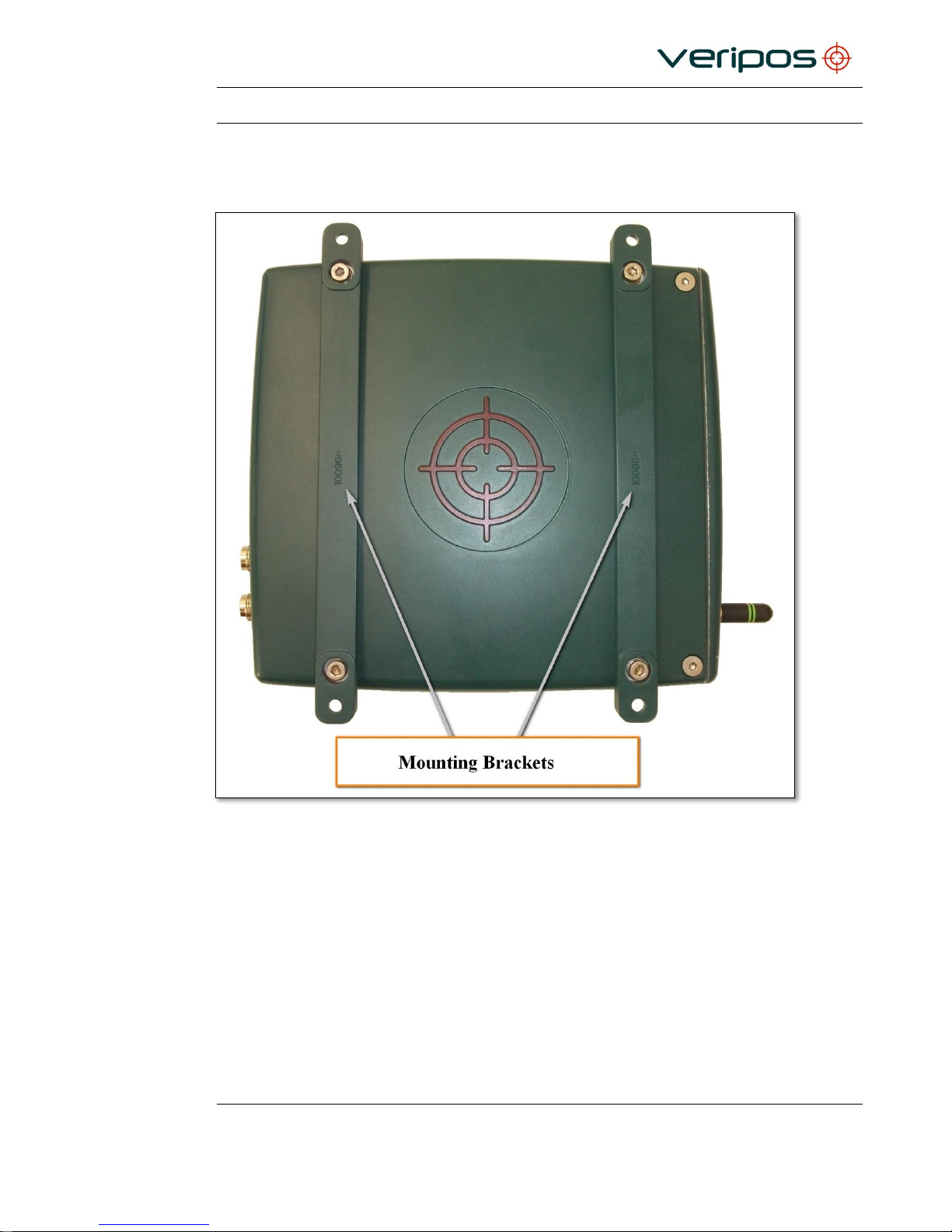
As shown above, two mounting brackets are attached to the bottom of the LD7. The
brackets may be mounted on the top or bottom of the LD7 housing. Two brackets are
supplied with each LD7 unit.
Page 53

Procedure Title:
LD7 Installation Manual
File Ref.:
AB-V-MA-00559
Rev No:
A7
Page 53
LD7 Features
272 Channel AsteRx2eH, with L1/L2/L2C GPS, GLONASS and SBAS.
GNSS Heading
Serial & Ethernet interfacing
Remote access via Ethernet
Configurable via WebUI
Bluetooth® (class 1)
GNSS Navigation Accuracy
Navigation Performance
Horizontal (m)
Vertical (m)
DGPS (RTCM1,3 / 9,3)
1.0 - Veripos APEX Ultra
0.1
0.2
GNSS Heading Accuracy
Separation
Heading
Pitch or Roll
1 metre
0.3°
0.6°
10 metre
0.03°
0.06°
 Loading...