

Veripos LD6 Installation Manual

LD6
Installation Manual
VERIPOS
Document title:
LD6 Installation Manual
Document No.
AB-V-MA-00520
Rev No:
L10
Page 2
Date:
03.04.2017
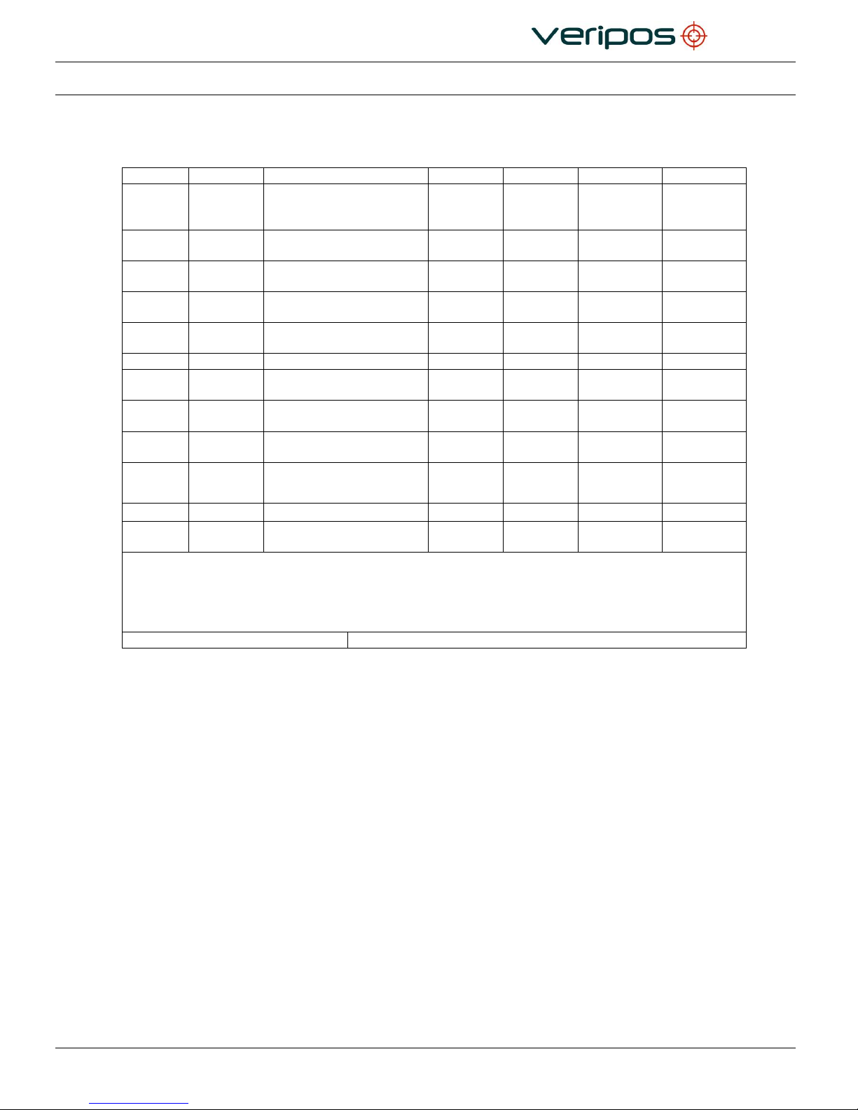
LD6 Installation Manual
L10
03/04/17
Variant table updated.
Changes to cable
termination section
AR
RM
RR
-
L9
06/01/17
Info relating to new LD6
variants added
AR
RM
RR
-
L8
20/04/16
GNSS Module tracking
specification updated
AR
RR
RR
-
L7
21/12/15
Safety warning info
updated
AR
AP
RR
-
L6
19/08/15
V460 antenna phase
centre info added
AR
RR
RR
-
L5
13/08/15
General minor updates
AR
-
L4
28/04/15
DC connector wiring
updated
AR
EM
EM
-
L3
31/03/15
Installation diagram
additions
AR
EM
EM
-
L2
09/02/15
Default COM port
amendments
AR
EM
EM
-
L1
30/09/14
Formatting and antenna
updates
AR
VA
EM
-
L
02/07/14
Updated contact details
AW
AW
RR
-
REVISION
DATE
DESCRIPTION
ORIGINATOR
CHECKED
APPROVED
CLIENT
APPROVED
Document Title:
LD6 Installation Manual
Document No: AB-V-MA-00520
File Ref: AB-V-MA-00520.doc

Document title:
LD6 Installation Manual
Document No.
AB-V-MA-00520
Rev No:
L10
Page 3
Date:
03.04.2017
LD6 Installation Manual
Table of Contents
1. INTRODUCTION ................................................................................................................................................................. 5
1.1 GENERAL .................................................................................................................................................................. 5
1.2 LD6 INTEGRATED MOBILE UNIT ............................................................................................................................ 5
1.3 SCOPE ...................................................................................................................................................................... 6
1.3.1 Contents ............................................................................................................................................... 6
1.4 TERMS AND ABBREVIATIONS ............................................................................................................................... 7
1.5 LD6 SAFETY SUMMARY .......................................................................................................................................... 9
1.5.1 Unpacking and inspection .................................................................................................................... 9
1.5.2 Safety symbols ..................................................................................................................................... 9
1.5.3 Safety warnings ................................................................................................................................... 9
1.5.4 Installation .......................................................................................................................................... 10
1.5.5 Maintenance ...................................................................................................................................... 10
1.5.6 Servicing ............................................................................................................................................ 10
1.5.7 Fault diagnosis ................................................................................................................................... 10
1.6 DOCUMENT CONVENTIONS ................................................................................................................................ 11
1.6.1 Typographical conventions ................................................................................................................ 11
1.6.2 Special Notices .................................................................................................................................. 11
1.7 REFERENCES ........................................................................................................................................................ 11
1.8 WASTE ELECTRICAL AND ELECTRONIC EQUIPMENT ..................................................................................... 12
1.8.1 Replacement of Battery ..................................................................................................................... 12
1.9 DISCLAIMER ........................................................................................................................................................... 13
2. SYSTEM DESCRIPTION ................................................................................................................................................... 15
2.1 LD6 RECEIVER OVERVIEW .................................................................................................................................. 15
2.2 EXAMPLES OF LD6 VARIANTS ............................................................................................................................. 16
2.3 CONTROLS, CONNECTORS AND I/O PORTS ..................................................................................................... 17
2.3.1 Front Panel ........................................................................................................................................ 17
2.3.2 Rear Panel ......................................................................................................................................... 17
3. INSTALLATION ................................................................................................................................................................. 18
3.1 INSTALLATION ....................................................................................................................................................... 18
3.1.1 LD6 Installation – Schematic Example 1 ........................................................................................... 18
3.1.2 LD6 Installation – Schematic Example 2 ........................................................................................... 19
3.2 SITING THE LD6 RECEIVER ................................................................................................................................. 20
3.2.1 Ventilation Requirements ................................................................................................................... 20
3.2.2 LD6 siting guides ............................................................................................................................... 20
3.3 ANTENNA INSTALLATION ..................................................................................................................................... 22
3.3.1 Antennas ............................................................................................................................................ 22
3.3.2 GNSS antenna ................................................................................................................................... 23
3.3.3 L-Band Antenna ................................................................................................................................. 25
3.3.4 MF Beacon Antenna .......................................................................................................................... 27
3.4 COAXIAL CABLE INSTALLATION .......................................................................................................................... 28
3.4.1 Times LMR 400 .................................................................................................................................. 28
3.4.2 Times LMR 240 .................................................................................................................................. 28
3.4.3 Maximum Recommended Cable Lengths .......................................................................................... 28
3.4.4 General .............................................................................................................................................. 28
3.5 COAXIAL CONNECTIONS TO LD6 MODULES ..................................................................................................... 30
3.5.1 Common Coaxial Connections .......................................................................................................... 30
3.5.2 Combined L-Band/ GNSS Antenna Variant ....................................................................................... 31
3.6 INTERFACE ............................................................................................................................................................ 32
3.6.1 LD6 Rear Connections ....................................................................................................................... 32
3.6.2 COM 1 – COM 14 .............................................................................................................................. 32
3.6.3 1PPS Output Option .......................................................................................................................... 33
3.6.4 Ethernet Interface .............................................................................................................................. 33

Document title:
LD6 Installation Manual
Document No.
AB-V-MA-00520
Rev No:
L10
Page 4
Date:
03.04.2017
LD6 Installation Manual
3.7 EQUIPMENT RACK ................................................................................................................................................ 36
3.7.1 Rack Installed LD6 Variant – Guidance on Installation ..................................................................... 36
3.8 POWER AND CABLING .......................................................................................................................................... 37
4. REFERENCE INFORMATION .......................................................................................................................................... 38
4.1 TECHNICAL SPECIFICATIONS ............................................................................................................................. 38
4.1.1 Mechanical ......................................................................................................................................... 38
4.1.2 Environmental .................................................................................................................................... 38
4.1.3 Electrical............................................................................................................................................. 39
4.1.4 Compass Safe Distance .................................................................................................................... 39
4.1.5 Antennas ............................................................................................................................................ 40
4.1.6 Summary Specification of Antennas .................................................................................................. 41
4.1.7 Legacy Antennas ............................................................................................................................... 44
4.1.8 Antenna Cables – Specifications ....................................................................................................... 47
4.1.9 Summary Specification of Module Receiver cards ............................................................................ 47
4.2 CABLING AND CONNECTORS .............................................................................................................................. 54
4.2.1 AC Power Connector ......................................................................................................................... 54
4.2.2 DC Power Connector ......................................................................................................................... 56
4.2.3 Times LMR 400 Coaxial Cable .......................................................................................................... 58
4.2.4 Times LMR 240 Coaxial Cable .......................................................................................................... 59
4.2.5 LMR 400 – Times Microwave TC-400-NM N-Type Male Connector ................................................. 60
4.3 INTERFACE AND SERIAL PORT INFORMATION ................................................................................................ 61
4.3.1 LD6 COM Ports .................................................................................................................................. 61
5. CONTACT INFORMATION ............................................................................................................................................... 62
5.1 VERIPOS HELPDESK............................................................................................................................................. 62
5.2 VERIPOS OFFICE LOCATIONS ............................................................................................................................. 62
5.2.1 VERIPOS UK ..................................................................................................................................... 62
5.2.2 Additional VERIPOS Offices .............................................................................................................. 62
Document title:
LD6 Installation Manual
Document No.
AB-V-MA-00520
Rev No:
L10
Page 5
Date:
03.04.2017
LD6 Installation Manual
1. INTRODUCTION
1.1 GENERAL
This document provides the information required to install an LD6.
When consulting this document it will help the installer to have available the following
items to assist in assessing and planning the work:
The VERIPOS LD6 and associated equipment shipped to site
The ‘Equipment Packing list’ (included with the equipment packing sent to site)
The LD6 Operations manual
The VERIPOS document “Antenna and Coaxial Cable Installation provided with
VERIPOS installation documentation
Interactive training modules and VERIPOS product literature on CD ROM.
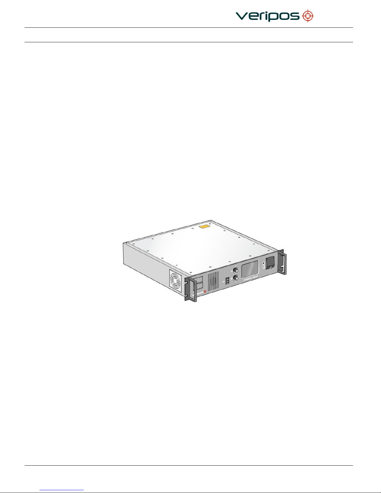
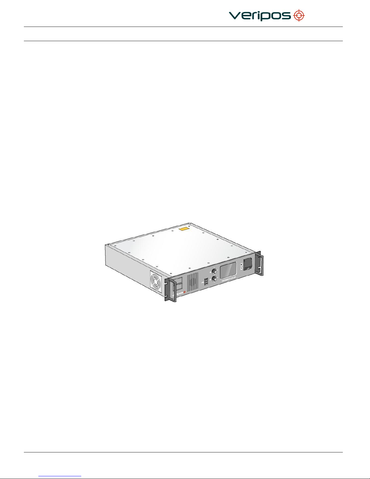
1.2 LD6 INTEGRATED MOBILE UNIT
Figure 1. The VERIPOS LD6 Receiver
The VERIPOS LD6 is easy to install and operate. It is an effective, flexible unit that
ensures reliable reception of VERIPOS services with superior positioning from metre to
decimetre level accuracy.
The LD6 integrated mobile unit is manufactured to the highest specifications and is
certified to EN60945:2002 [5].
It is designed as a standardised, upgradeable L-band receiver that is simple to operate
and maintain.
The LD6 is provided in a number of variants and can be upgraded as required to
generate any VERIPOS proprietary position solution depending on the data
subscriptions enabled.
The LD6 is modular and can be upgraded as required from a “black box” mode to
generating any VERIPOS proprietary position solution depending on the data
subscriptions enabled.
LD6 variants may be used as a sensor to output received data and GNSS
measurements to external processing or quality control software such as the VERIPOS
DP Orion or Verify QC.

Document title:
LD6 Installation Manual
Document No.
AB-V-MA-00520
Rev No:
L10
Page 6
Date:
03.04.2017
LD6 Installation Manual
The LD6 has a 3.5” (9 cm) colour VGA touchscreen that allows quick and easy user
setup.
In addition to calculating position, the LD6 can output all received data in standard
formats such as RTCM and NMEA.
The LD6 is exceptionally flexible. For most variants overall operating status can be
determined using the front panel display.
1.3 SCOPE
The purpose of this manual is to provide the necessary information to perform the
installation of the VERIPOS LD6 Integrated mobile unit. It covers installation of:
Antennas
Coaxial and data cables
LD6 receiver and power requirement
Housings and ancillary equipment provided with the LD6.
1.3.1 Contents
This manual provides guidance for engineers to install a VERIPOS LD6 receiver on a
vessel.
Details are provided to assist in locating and connecting equipment ready to be
commissioned. The manual covers installation of LD6 receiver variants.
Read this manual in conjunction with the specific ‘Scope of Supply’ or Equipment
Packing List’ for your particular installation.
Chapter Contents
1. Introduction This chapter specifies the purpose and target group for
the manual. It also contains a list of used abbreviations
and a specification of the document conventions.
2. System description This chapter describes the interface in detail on the front
and back side of the LD6 unit.
3. Installation This chapter covers the installation of the LD6 unit as
well as cabling guidelines.
4. Reference information This chapter comprises additional information such as
Technical Specifications, cable specifications, connector
termination and connector pin assignments.
5. Contact information This chapter contains contact information details about
the VERIPOS Helpdesk and VERIPOS offices
worldwide.

Document title:
LD6 Installation Manual
Document No.
AB-V-MA-00520
Rev No:
L10
Page 7
Date:
03.04.2017
LD6 Installation Manual
1.4 TERMS AND ABBREVIATIONS
A Ampere
AC Alternating Current
Apex Veripos PPP DGNSS service
ARP Antenna Reference Point
AWG American Wire Gauge
BDE Below Deck Equipment
BeiDou Chinese GNSS constellation
BER Bit Error Rate
bps Bits Per Second
CoG Course Over Ground
DC Direct Current
DGPS Differential GPS
DGNSS Differential GNSS
DOP Dilution of Precision
DP Dynamic Positioning
EGNOS European Geostationary Navigation Overlay Service
EIA Electronics Industry Association (this document uses the previous
terminology “RS” that is generally recognized in the industry)
EMC ElectroMagnetic Compatibility
Galileo European GNSS constellation
GDOP Geometric Dilution of Precision
GLONASS Global Navigation Satellite System – Russian equivalent to
GPS Global Positioning System
GNSS Global Navigation Satellite System
HDOP Horizontal Dilution of Precision
HDT NMEA message containing heading information
HF High Frequency Radio – used to transmit correction data
Hz Hertz
Kgf Kilogramme Force
KHz Kilohertz
KPH Kilometres per Hour
LAN Local Area Network
LNA Low Noise Amplifier
L-Band Method of transmitting correction data to mobile users
LCD Liquid Crystal Display

Document title:
LD6 Installation Manual
Document No.
AB-V-MA-00520
Rev No:
L10
Page 8
Date:
03.04.2017
LD6 Installation Manual
MF Medium Frequency Radio used to transmit correction data
MHz Mega-Hertz
NMEA National Marine Electronics Association
N/A Not applicable
PDOP Positional Dilution of Precision
PPP Precise Point Positioning
PPS Pulse per Second
PRN Pseudo Random Noise
QZSS Japanese GNSS constellation
RF Radio Frequency
RMS Root Mean Square
RoHS Restrictions of Hazardous Substances
RTCM Radio Technical Commission for Maritime Services
SAL Service Access License
SBAS Satellite Based Augmentation System
SD Standard Deviation
SNR Signal to Noise Ratio
Spotbeam High Power L-Band Signal
SV Space Vehicle
UHF Ultra High Frequency
Ultra Veripos High Accuracy Positioning Systems
USB Universal Serial Bus
UTC Coordinated Universal Time
V Volt
VDOP Vertical Dilution of Precision
VERIPOS Precise navigation and positioning solutions service provider
VGA Video Graphic Array
VOSS VERIPOS Online Support System
W Watt
WAAS Wide Area Augmentation System
WEEE Waste Electrical and Electronic Equipment

Document title:
LD6 Installation Manual
Document No.
AB-V-MA-00520
Rev No:
L10
Page 9
Date:
03.04.2017
LD6 Installation Manual
1.5 LD6 SAFETY SUMMARY
This section summarizes safety guidelines when installing the LD6 unit.
1.5.1 Unpacking and inspection
Carefully unpack the unit and retain packaging to return the equipment where required.
Inspect the unit. If the equipment appears damaged return it using the original
packaging. Responsibility for damage is not accepted if the approved packaging is not
used.
Ensure all items and ancillary equipment is present. Contact your supplier or VERIPOS
where this is not the case (see contacts in the Contact information chapter).
1.5.2 Safety symbols
Please see section 1.6 Document conventions later in this manual.
1.5.3 Safety warnings
Always observe the following safety precautions:
Disconnect power from both AC and DC inlets on the rear panel to isolate
the equipment before working on it.
Never use a detachable AC/DC supply cord with inadequate rating.
If the equipment is used in a manner not specified by VERIPOS, the
protection provided by the equipment may be impaired.
Ensure adequate air circulation to ventilate the unit especially to the sides to
avoid heat build-up.
Only connect to an earthed power supply. The LD6 unit is class 1
construction and must be earthed.
Connect only to a power supply with a voltage corresponding to that marked
on the unit.
Always disconnect the LD6 and associated equipment from the mains when
connecting equipment, inserting/removing modules by removing the AC/DC
supply and ancillary connections before removing from the rack.
NOTE
There is a retention clip which, when used, prevents accidental
removal of the AC power plug.
The equipment is heavy: use handles where provided.
The equipment is for use in moderate climates only. Never use the
equipment in damp or wet conditions.
Avoid excessive heat, humidity, dust and vibration.
Do not use where the equipment may be subjected to liquids.
Always use the power connections supplied with the unit. See the Reference
information chapter for details.
Before replacing a fuse disconnect the equipment from both AC and DC
supplies.

Document title:
LD6 Installation Manual
Document No.
AB-V-MA-00520
Rev No:
L10
Page 10
Date:
03.04.2017
LD6 Installation Manual
1.5.4 Installation
Ensure the AC and/or DC power supplies are disconnected during installation. The
power connections are easily accessed on the rear of the unit (see Figure 4 in the
System Description chapter).
Ensure that the unit is secured within the rack by the supplied brackets and fittings.
Position the unit to ensure there is ample spacing for ventilation of the unit and access to
front and rear during normal operation.
Ensure all cables are routed safely to avoid sharp edges, bends and pinches.
Ensure only the specified cables are used for interconnection of the equipment.
Permanently connect the vessels’ protective earth to the protective bonding connection
on the unit.
1.5.5 Maintenance
Clean the unit using a clean dry cloth only. Do not wet the unit or allow moisture to
penetrate the unit. Do not use solvents to clean the unit.
Fuses must only be replaced using a fuse of the type and rating as marked.
If a replacement fuse fails: immediately contact your local service agent. Do not replace
the fuse with one of a higher value.
1.5.6 Servicing
This unit contains no user-serviceable parts. Please refer all repairs to a qualified
service agent or to VERIPOS. See the Reference information chapter for details.
1.5.7 Fault diagnosis
Follow the guidance in this document to correctly install the LD6. Where the LD6 does
not perform as indicated please first check all connections before contacting your
supplier or VERIPOS for assistance (contact details in the Reference information
chapter).
Document title:
LD6 Installation Manual
Document No.
AB-V-MA-00520
Rev No:
L10
Page 11
Date:
03.04.2017
LD6 Installation Manual
1.6 DOCUMENT CONVENTIONS
1.6.1 Typographical conventions
Italic or bold text is used to emphasize certain parts of the information. Italic is also used
in cross-references to other parts of the document.
Bold text is also used for indicators and touch screen “push-buttons” commands.
“Text within quotes” is used when display screens are mentioned in text. Monospace text
is used for input/output strings to/from the device.
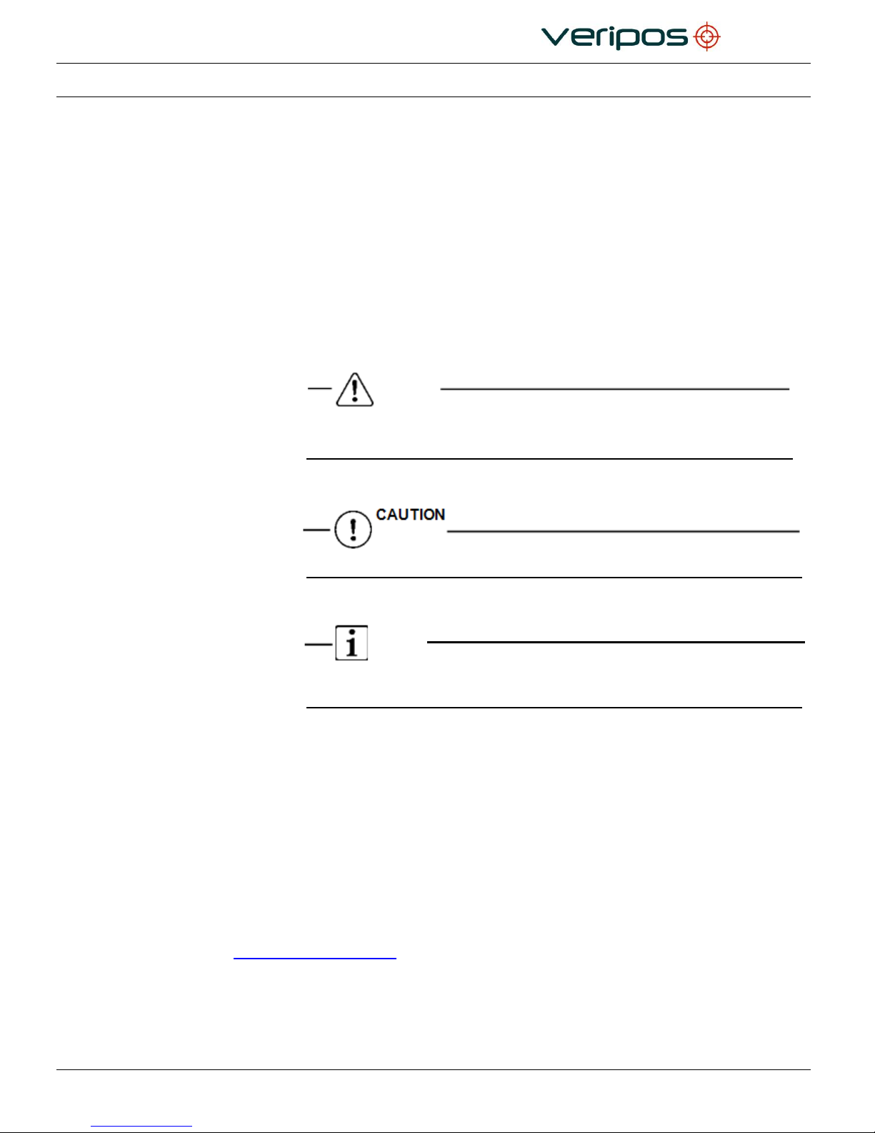
1.6.2 Special Notices
WARNING
A warning indicates the risk of bodily harm or serious damage to
the hardware.
A caution indicates the risk of damaging the hardware.
NOTE
A note shows important information that helps you make better use of the system.
1.7 REFERENCES
Please read this manual and refer to the following information where required:
Antenna & Coaxial Cable Installation manual.
LD6 Operations manual. Ensure manual is valid for LD6 variant in-use!
LD6 Quick Guide.
Information is available at VERIPOS Online Support System (VOSS):
http://help.veripos.com
Document title:
LD6 Installation Manual
Document No.
AB-V-MA-00520
Rev No:
L10
Page 12
Date:
03.04.2017
LD6 Installation Manual
1.8 WASTE ELECTRICAL AND ELECTRONIC EQUIPMENT
The Waste Electrical and Electronic Equipment Directive (hereinafter referred to as the
“WEEE directive”) places an obligation on EU-based manufacturers, distributors,
retailers and importers to take back electronics products at the end of their useful life. A
sister directive, RoHS (Restriction of Hazardous Substances) complements the WEEE
directive by banning the presence of specific hazardous substances in the products at
the design phase. The WEEE directive covers all VERIPOS products imported into the
EU as of August 13, 2005. EU-based manufacturers, distributors, retailers and importers
are obliged to finance the costs of recovery from municipal collection points, reuse, and
recycling of specified percentages per the requirements contained in the WEEE
Directive.
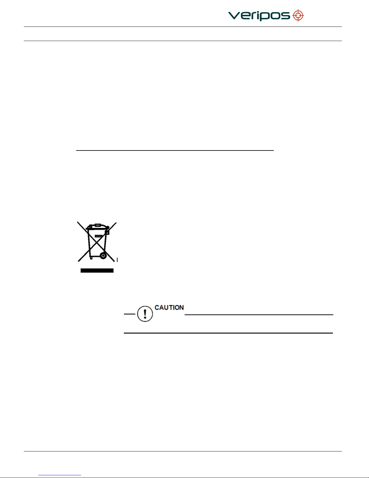
Instructions for disposal of WEEE by users in the European Union.
Products which have the undernoted symbol located on either the product itself or its
packaging indicates that the product must not be disposed of with other waste. Instead,
it is the user’s responsibility to dispose of their waste equipment by handing it over to a
designated collection point for the recycling of WEEE.
The separate collection and recycling of your WEEE at the time of disposal will help to
conserve natural resources and ensure that it is recycled in a manner that protects
human health and the environment. For more information about recycling centres,
please contact the local city office, the household waste disposal service or the product
supplier.
1.8.1 Replacement of Battery
Risk of explosion if battery is replaced by an incorrect type.
Where replacement of the battery unit in the LD6 is required, please carefully dispose of
the LD6 battery as hazardous waste in line with local regulations that apply.

Document title:
LD6 Installation Manual
Document No.
AB-V-MA-00520
Rev No:
L10
Page 13
Date:
03.04.2017
LD6 Installation Manual
1.9 DISCLAIMER
Veripos Limited (hereinafter referred to as “Veripos”) has taken every care in the preparation of
the content of this Manual (“Manual”). This Manual is provided “as is” without any
representations or warranties, express or implied. Veripos makes no representations or
warranties in relation to this Manual and the content provided herein. Veripos reserves the right
at its sole discretion, but without any obligation, to make amendments or improvements to, or
withdraw or correct any error(s) or omission(s) in any portion of the Manual without notice.
Although Veripos makes a reasonable effort to include accurate and up to date information,
Veripos does not warrant or guarantee that this Manual and its contents are current, complete,
accurate and/or free from errors.
Copyright © 2004-2017 VERIPOS
All rights reserved. No part of this Manual and its contents may be reproduced, copied, re-
engineered, adapted, redistributed, published, commercially exploited or transmitted in any
form, by any means, electronic or mechanical, including photocopying or recording, without the
express prior written permission of Veripos. Applications for any written permission should be
addressed to Veripos House, 1B Farburn Terrace, Dyce, Aberdeen, AB21 7DT, United
Kingdom.
Unauthorised reproduction, copying, re-engineering, adaption, redistribution, publication or
commercial exploitation of this Manual or its contents may be subject to civil as well as criminal
sanctions under the applicable laws. Where Veripos’ intellectual property rights are alleged to
be infringed by the end user, Veripos will seek to enforce its intellectual property rights in the
civil courts to the fullest extent possible. Where reproduction, copying, re-engineering, adaption,
redistribution, publication or commercial exploitation of this Manual or its contents has been
permitted by Veripos in accordance with this disclaimer, then no changes in the Manual or
deletion of any kind to the Manual will be made by end user. End user acknowledges that it
does not acquire any ownership rights by accessing, viewing or utilising this Manual and agrees
that it shall not hold itself out to any third party as having any ownership rights to this Manual.
The end user shall save, indemnify, defend and hold Veripos harmless on written demand, from
all claims, losses, damages, costs (including legal costs), expenses and liabilities of any kind
and nature, invoked against Veripos by any third party, for or arising out of, any alleged
infringement of any patent or proprietary or protected right arising out of or in connection with
the utilisation of this Manual by the end user and/or in connection with any representation to
third parties of ownership of any kind with respect to this Manual by the end user.
To the fullest extent permitted by applicable laws, Veripos hereby excludes liability, for any
damages, direct or indirect, punitive, incidental, special, consequential or other damages arising
out of or in any way connected with the use of, reference to, reliance on or inability to use this
Manual and its contents, including without limitation, any loss of profits, business interruption or
damage. These limitations shall apply even if Veripos has been expressly advised of the
potential loss.
This disclaimer and the exclusions herein shall be governed by and construed in accordance
with English law. If any provision of this disclaimer and/or exclusions are held to be unlawful,
void or for any reason whatsoever, unenforceable, then that provision shall be deemed
severable and shall not affect the validity and enforceability of the remaining provisions of this
disclaimer.

Document title:
LD6 Installation Manual
Document No.
AB-V-MA-00520
Rev No:
L10
Page 14
Date:
03.04.2017
LD6 Installation Manual
This page is intentionally left blank.
Document title:
LD6 Installation Manual
Document No.
AB-V-MA-00520
Rev No:
L10
Page 15
Date:
03.04.2017
LD6 Installation Manual
2. SYSTEM DESCRIPTION
This section gives an outline description of the VERIPOS LD6 receiver and the
components used for LD6 that may be supplied.
This section gives overall information and details as follows:
LD6 Receiver Overview
Hardware Variants
Controls, Connectors and I/O Ports
2.1 LD6 RECEIVER OVERVIEW
The VERIPOS LD6 receiver is a multi-purpose unit built on a modular design. A
touchscreen colour control panel is used to set up the unit and display information.
Various combinations of modules can be installed. Contact VERIPOS for further
information.
Figure 2. The VERIPOS LD6 Receiver
LD6 comprises:
Housing with power supply
Controller
Interfaces for data output
Cooling
Display/control touchscreen interface
Modules (optional):
Single input GNSS receiver
L-Band receiver
MF beacon receiver
UHF receiver
Document title:
LD6 Installation Manual
Document No.
AB-V-MA-00520
Rev No:
L10
Page 16
Date:
03.04.2017
LD6 Installation Manual
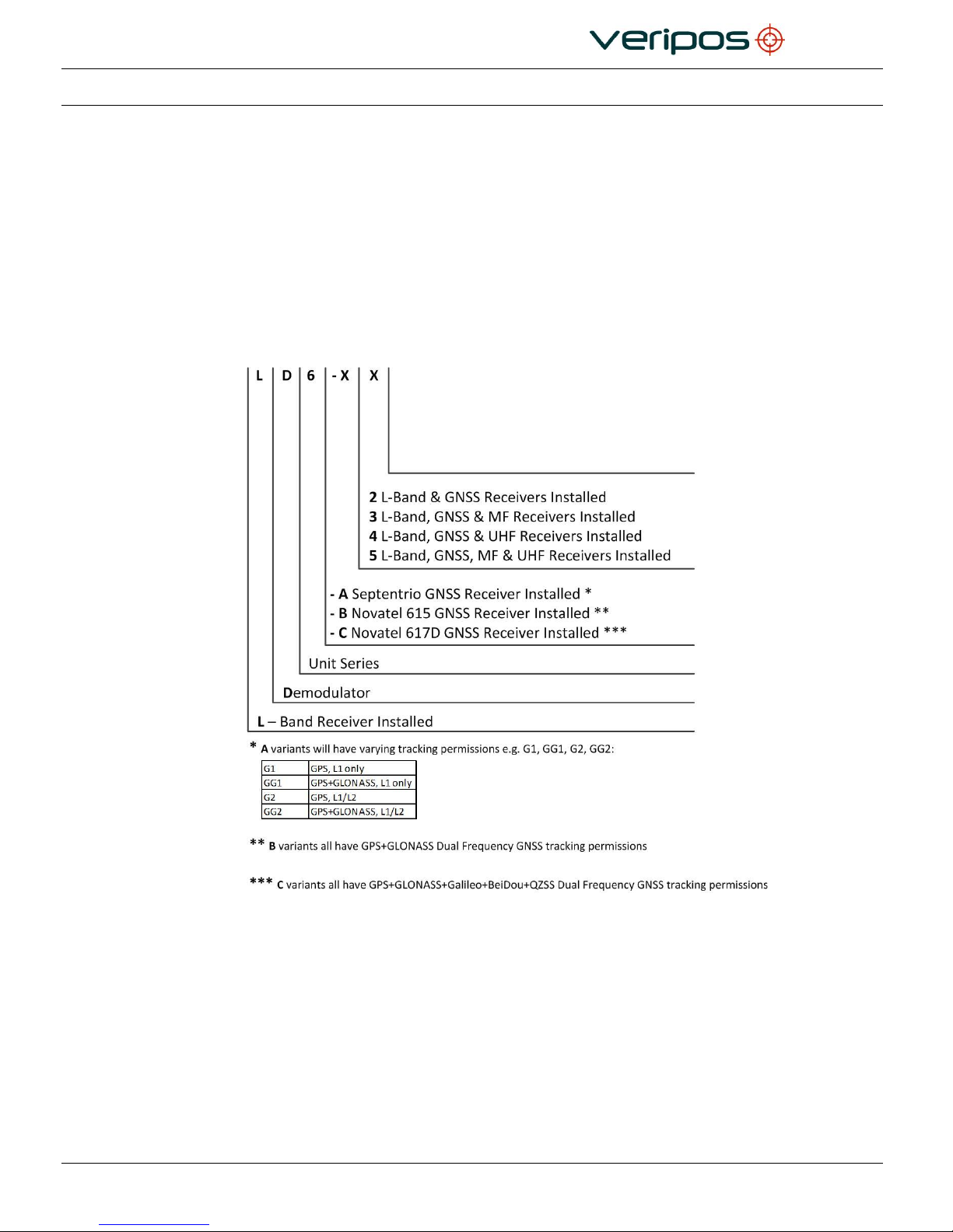
2.2 EXAMPLES OF LD6 VARIANTS
LD6 models with a GNSS receiver card can deliver a full DGNSS
positioning system, capable of computing multi-reference DGNSS
and may use VERIPOS Ultra or Apex solutions capable of outputting
position data in NMEA format.
Variants with an MF module installed allow the LD6 to be capable of
receiving third party corrections directly from local reference
stations (where available).
Variants with UHF module where used, allow the LD6 to receive
corrections by UHF broadcast where available.
LD6’s running software version 50.1.0.7 and below (A variant) are fitted with Septentrio AsteRx
GNSS cards. The GNSS tracking permissions enabled on these cards may vary.
LD6’s running software version 101.x.x.x (B variant) are fitted with NovAtel OEM615 GNSS
cards, which are capable of tracking GPS+GLONASS GNSS constellations.
LD6’s running software version 103.0.0.8 and above (C variant) are fitted with NovAtel
OEM617D cards, which are capable of tracking up to 5 GNSS constellations.
The menu structure and general operation may vary depending on the LD6 software version.
Refer to the relevant LD6 Operations Manual for the software version running on your LD6.
Document title:
LD6 Installation Manual
Document No.
AB-V-MA-00520
Rev No:
L10
Page 17
Date:
03.04.2017
LD6 Installation Manual
2.3 CONTROLS, CONNECTORS AND I/O PORTS
The controls etc. are detailed in this chapter.
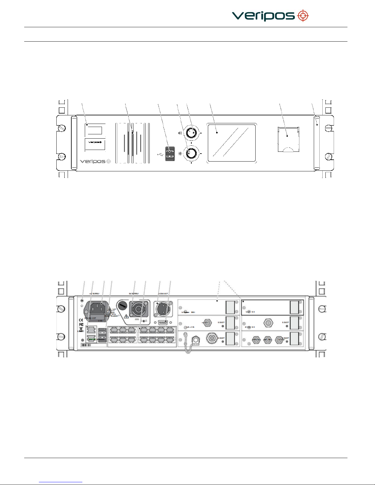
2.3.1 Front Panel
1 2 3 4 5 6 7 8
Figure 3. LD6 Front Panel
1. Labels with Unit ID (above) and phone number to Helpdesk (below)
2. Front panel speaker
3. 3 x USB 2.0 sockets
4. Screen brightness control
5. Volume control (press to mute/un-mute)
6. Colour touchscreen display
7. Front panel power on/off switch (with security cover)
8. Removable handle (one on each side).
2.3.2 Rear Panel
1 2 3 4 5 6 7 8 9
Figure 4. LD6 Rear Panel
1. Earth bonding connector
2. 2 x Ethernet LAN ports
3. AC power input (with fuse)
4. 3 x USB 2.0 sockets
5. DC power input (with fuse)
6. 14 x Serial outlet ports (RS-232/422)
7. Mono audio outlet
8. Screen VGA/SVGA/XVGA/SXVGA output
9. 6 x Optional module bays with antenna connections
Document title:
LD6 Installation Manual
Document No.
AB-V-MA-00520
Rev No:
L10
Page 18
Date:
03.04.2017
LD6 Installation Manual
3. INSTALLATION
This section provides guidance on the installation of the LD6 receiver variants.
Contact your supplier or VERIPOS with questions or for advice when installing this
equipment.
3.1 INSTALLATION
Installation work for the LD6 varies for:
The types of antenna(s) to be installed
The LD6 variant in-use.
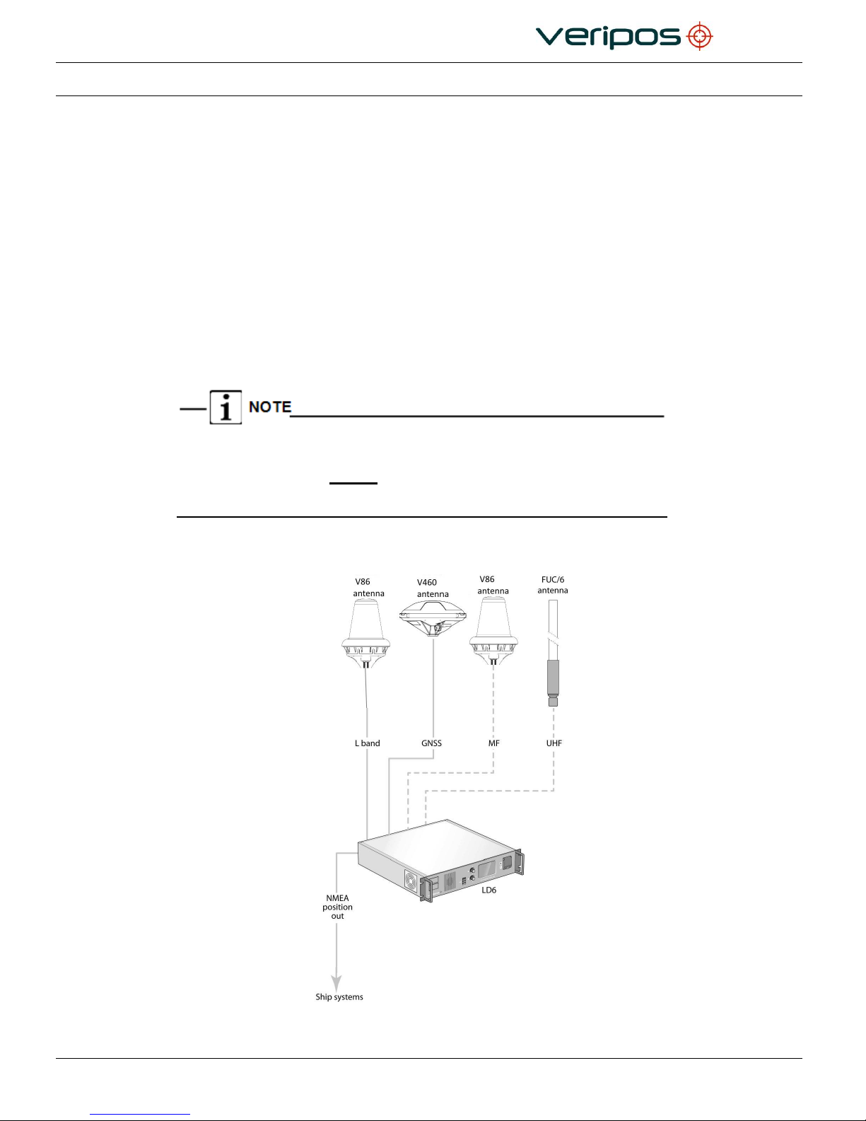
Examples are shown below to illustrate arrangement of typical installation of antennas
and position output from the LD6.
The diagrams shown in this section are examples of possible antenna setup
arrangements. Please be aware that other antenna configurations are possible. For
long-term installations, always contact VERIPOS to obtain setup drawings specific to
your installation as these may differ from those shown in this section.
3.1.1 LD6 Installation – Schematic Example 1
Figure 5. Example of an Installation Drawing for an LD6
Document title:
LD6 Installation Manual
Document No.
AB-V-MA-00520
Rev No:
L10
Page 19
Date:
03.04.2017
LD6 Installation Manual
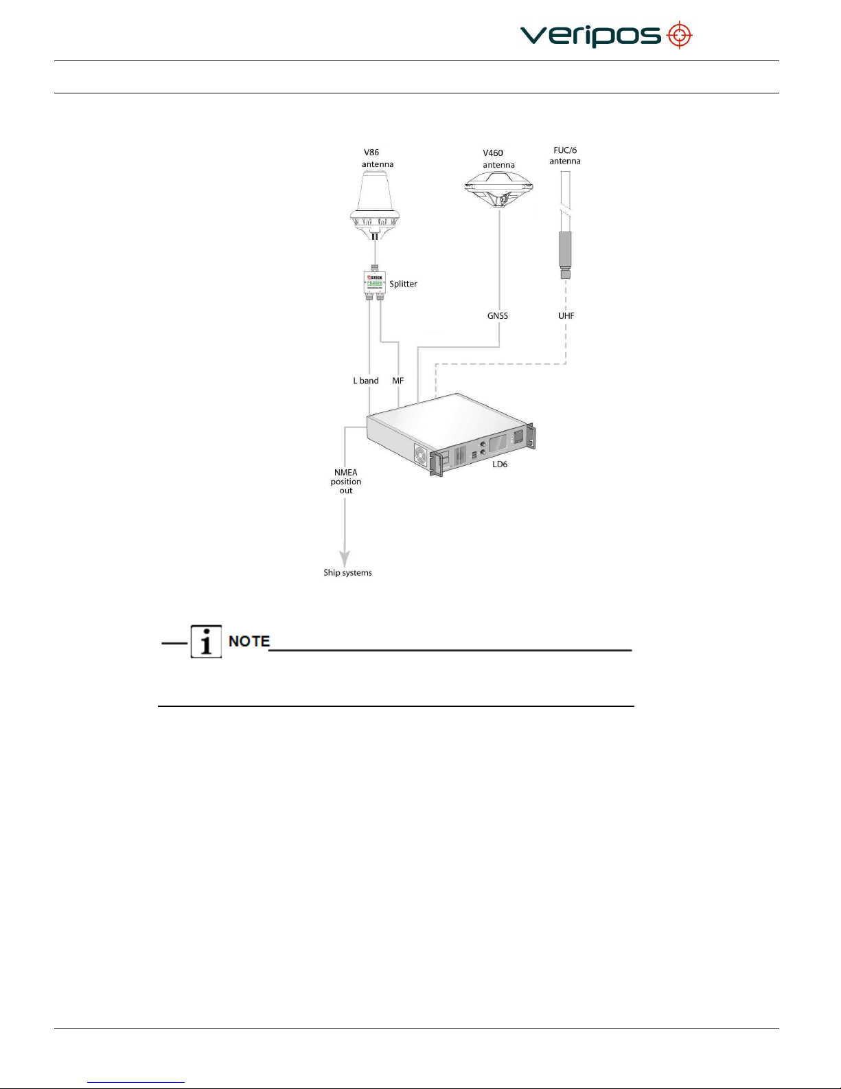
3.1.2 LD6 Installation – Schematic Example 2
Figure 6. Example of an Installation Drawing for an LD6 – Shared L-Band & MF antenna
The splitter used in the Figure 6 configuration will be supplied by VERIPOS.
Normal GNSS splitters will not allow MF signals to pass through.
 Loading...