

Veripos LD2 Quick Manual
VERIPOS LD2 Quick guide
VOSS: http://help.veripos.com
AB-V-MA-00545 Rev A1
1. Use cables & adaptors supplied:
Antenna tails (L-band N-Type
/GNSS TNC) to suit
1 x AC power lead
Optional - DB9– DB9 serial output
cables to suit configuration
2. Antennas: - see LD2 Installation manual for more information.
GNSS
e.g.V460, GA530
AD491
L-Band
e.g.90984, V86
MF Marine Beacon
(Optional)
e.g.CDA-3, A31
HF
(Optional)
DHM 5000
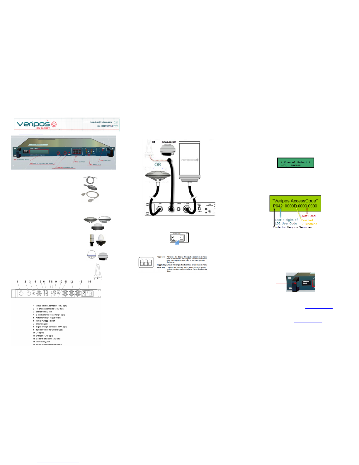
3. Connecting the LD2 - make connections to the LD2 as shown;
4. Turn on LD2 power at rear and wait until unit has initialized;
Use the front panel keys to navigate and set up the LD2 screen:
5. Beam Selection
To use Veripos corrections the LD2 must be synced to a geostationary satellite beam.
A more detailed description is in the LD2 Operations Manual.
Select a Veripos correction satellite beam for your vessel work area:
Press Page until Main Menu / Configuration
Enter 1x to Configuration / Demodulator
Enter 1x to Channel Select. Enter.
Toggle until beam required is shown, Enter.
Toggle from N to Y, Enter.
> chevron shows beam in use.
6. Enable for Veripos Corrections
The LD2 needs to be synced to a regional beam before enabling.
Press Page until Access Code shows, then Enter to view current status:
Service Access Licence number (SAL). This is the contract number for
augmentation services provided by Veripos to you / your client and must be
provided when requesting service activation / deactivations.
User Code for the IMU – this is the unique 5 code number printed on the IMU
chassis.
The Veripos Augmentation Service(s) required – advise the Helpdesk of the
name / type of service appropriate to your requirements and IMU.
Once you have this information contact the Veripos Helpdesk to request unit
activation, quoting your User Code and Service Access Licence (SAL) number.
Provide the unique 5 digit User Code shown on the LD2 front panel (above).
You can download a Service Notification Form from http://help.veripos.com to use
when contacting the Veripos Helpdesk .Provide the details requested and type of
Service(s) you require, e.g. Veripos Ultra with Verify DP.
Tel. +44 1224 965900 email: helpdesk@veripos.com
Beam
Coverage
143.5E
Asia, Australasia, Indian Ocean
POR
East Asia, Australasia, Alaska
IOR
Asia, Indian Ocean, East Africa, Persian Gulf,
Caspian Sea
25E
North Sea, Mediterranean Sea, Africa, Persian
Gulf, Caspian Sea
AORW
North America, Gulf of Mexico, South America
98W
North America, Gulf of Mexico, South America
AORE
North Sea, Mediterranean Sea, Africa
VERIPOS LD2 Quick guide
VOSS: http://help.veripos.com
AB-V-MA-00545 Rev A1
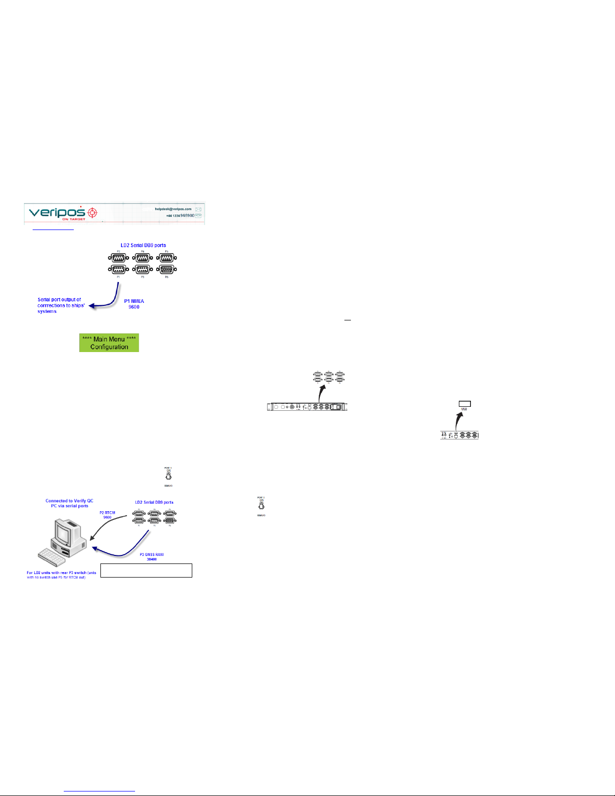
Internal Solution output
To output NMEA data on P1:
Go to Main Menu/Configuration and access the Serial Ports configuration menus by pressing
Enter then Page twice.
Set P1 to Local (using Toggle then Enter) - the P1 output will be generated by the LD2 processor
and algorithms (as GGA).
If P1 is set to GPS Rx - the P1 output is generated by the GNSS card and will be a ZDA
message, usually used in conjunction with a 1 PPS output harness.
To amend Messages output from P1 (Local):
Configuration/GPS Receiver/ Port A Settings then toggle to show message options and use
Enter/Toggle/Enter to add message strings required to the P1 Local output.
7. Verify QC Serial Port Solution output (Typical)
On the rear of the LD3 set P3 switch to GPS and set the PC port baud rates.
Serial ports
Serial ports are used to make connections to ships systems or Verify QC.
You can view and amend baud rates, outputs or inputs, etc. by navigating to Main
menu / Configuration screen & access the Serial Ports configuration menu by
pressing the Enter key followed by the Page key twice.
This provides access to the six sub menus which allow the user to set the
parameters and options for all Port outputs.
Qualifiers: - Where P3 is set to “Remote” (not to “GPS”)
- P2 and P4 used for output of RTCM messages
DB9 EIA232 Pin out
2 Received Data
3 Transmitted Data
5 Signal Ground
There are five RS-232 ports, one VGA output, one USB and a LAN port.
Port 1 – D9
When set to “LOCAL”, port 1 is the
primary NMEA output for position
from the processor algorithm. When
set to “GPS RX”, port 1 outputs a
ZDA time message. A 1 PPS output
can also be taken from P1 to use in
conjunction with the ZDA message.
Port 2 – D9
Port 2 is the primary RTCM output
and is used for internal corrections by
the processor algorithms.
The processor card is capable of
utilizing 4 stations in this way.
Port 3 – D9
Port P3 is used for the remote control
of the GPS Receiver and the
Demodulator Board.
GPS Gives Raw GPS out, when the
Port 3 switch on the back panel of the
LD2 is in the GPS (up) position.
DEM (Demodulator) gives access to
the Demodulator for Firmware
upgrades when the switch on the
back panel of the LD2 is in the
REM I/O position.
SKT (socket) allows for NMEA type
messages to be output, when port B
on the GPS LD2 has been configured
to output such messages. It also is
used for input of data of GYRO and
xRTCM messages.
OFF No data is input or output from
the port.
Port 4 – D9
Port 4 is the secondary RTCM output.
N.B. By default all stations set to
OFF.
Port 5 – D9
Port 5 is the GPS I/O port. It is
internally connected to Port A of the
GNSS card. When the Port 5 setting
is switched to "Remote", raw GNSS
measurements are available on Port 5
for use with external positioning
software such as Veripos' Verify QC.
In this mode the GPS menu system
becomes disabled and the LD2
processor stops calculating a position.
When the Port 5 setting is switched to
“Off”, the GPS configuration menu’s
become active again and Port 5
becomes disabled.
Port 6 – HD15
This is the VGA port, used to connect
an external monitor to the LD2. Only
used when Verify DP is activated and
in use.
The USB port can be used to set
inputs for xRTCM corrections or a
GYRO compass heading input for
display (using on- board Verify DP
software)
8. Check LD2 Status
For the LD2 to provide a differential position and RTCM outputs, it must be locked to
the correct communications satellite (“beam” or “channel”) for the current vessel
location.
To display which beam is selected, the strength of signal and the lock status.
Press Page until screen displays Main Menu/Status
Press *Enter* and screen will display:
Status /Demodulator
Press Enter/Page/Enter to access the Signal Status page
9. Beam Table updates
Veripos beam tables are updated for users over the air.
Where a unit has not been used for an extended period, customers may request a
refresh for the LD2 from the Helpdesk or see the LD2 Operation Manual for Channel
16 Edit details.
N.B. If your LD2 has no rear P3 switch, set
P5 to Remote (see later in this section )
 Loading...