


Nextiva S3100 Series
User Guide
Covering the S3100, S3100-BR, and
S3100-RP
Firmware Release 4.12
October 2007


Nextiva S3100 Series
Covering the S3100, S3100-BR, and S3100-RP
Firmware Release 4.
User Guide
12
Verint Video Intelligence Solutions Revision: B

This document contains confidential and proprietary information of Verint Systems Inc. and
is protected by copyright laws and related international treaties. Unauthorized use,
duplication, disclosure or modification of this document in whole or in part without the
written consent of Verint Systems Inc. is strictly prohibited.
By providing this document, Verint Systems Inc. is not making any representations
regarding the correctness or completeness of its contents and reserves the right to alter
this document at any time without notice.
All marks referenced herein with the ® or TM symbol are registered trademarks or
trademarks of Verint Systems Inc. or its subsidiaries. All rights reserved. All other marks
are trademarks of their respective owners.
© 2007 Verint Systems Inc. All rights reserved.
www.verint.com/videosolutions
Publication date: October 10, 2007

Contents
Preface .............................................................................................................. vii
Who Should Read this Guide ............................................................................viii
How to Use this Guide .....................................................................................viii
Conventions .............................................................................................viii
Related Documentation ..............................................................................viii
Related Products ............................................................................................. ix
About Us ........................................................................................................ ix
Warranty .........................................................................................................x
Chapter 1
About the S3100 Series .....................................................................................2
Shipment ........................................................................................................2
Casing Description ......................... .. ........................... ......................................3
Chapter 2
Available Frequency Bands and Channels ...................................... .. .....................6
Wireless Cells ....................................... .. ... .................................................... ..8
System Planning ............................................................................................12
Application Types ........................................................................................... 15
Colocated Cells .............................................................................................. 20
RF Planning ...................................................................................................25
Overview ..........................................................................................1
S3100 ....................................................................................................... 4
S3100-BR and S3100-RP ............................................................................. 4
System and RF Planning ...................................................................5
2.4 GHz Band .............................................................................................6
4.9 GHz Band .............................................................................................6
5 GHz Band ................................................................................................7
Roles .........................................................................................................8
Compatibility Issues ....................................................................................8
Video Bit Rate and Data Throughput ............................................................10
MAC Protocols ..........................................................................................13
TPC .........................................................................................................13
DFS ........................................................................................................14
Access Point ...................................... .......................... .. .. .. .......................16
Point-to-Multipoint Repeater .......................................................................16
Point-to-Point Repeater .............................................................................17
Wireless Bridge .............................. ............................ .. ........................... ..18
Wireless Bridge Repeater ....................................................................... .. ..19
Distance Limitations ....................................................... .. .........................20
General Guidelines ....................................................................................20
4.9 GHz Band in North America ................................................................... 20
5 GHz Band in North America and 2.4 GHz Band ........................................... 21
5 GHz Band in Europe ................................................................................22
Location Evaluation ................................................................................... 25
Antenna Requirements ..............................................................................26
Interference ............................................................................................. 27
RF Exposure Considerations .......................................................................27
Verint Video Intelligence Solutions iii

Contents
Chapter 2 Configuring and Installing the Device .............................................29
Computer Requirements ..................................................................................30
Point-to-Point Repeater ...................................................................................30
Access Point .......................................... ... .. .. ......................... .. .. .....................31
Point-to-Multipoint Repeater .............................................................................32
Wireless Bridge ................................. .. .. .........................................................33
Wireless Bridge Repeater ........................... .. ........................... .. .. .....................34
Power Connections ..........................................................................................35
Power over Ethernet ..................................................................................36
24V DC Power ......................................... .. .. ......................... .. ...................37
Configuration .................................................................................................37
Changing the IP Address of the Computer .......................... .. .. .......................37
Device Preparation ................................................ ... .. ...............................41
IP Parameters ...........................................................................................41
Country Selection and Device Name .............................................................43
Wireless Parameters .............................. .. ........................... .......................44
Communication Checking ...........................................................................47
Installation ....................................................................................................47
Installation of the S3100-RP Devices ............................................................47
Installation of the S3100-BR Devices ...........................................................48
Installation of the S3100 Access Point Device ................................................49
Installation of the Antenna .........................................................................50
Firmware Update ........................................ .. ......................... .. .. .....................50
Quality of Service ...........................................................................................51
LEDs .............................................................................................................51
Duplicate Master Detection ...............................................................................52
Finding a “Lost” S3100 ....................................................................................53
Chapter 4
Setting Parameters with the CLI .....................................................55
Getting Started ..............................................................................................56
Access Management ........................................................................................57
User Accounts ......................................... ......................... .. .. .....................57
Security ................................................................................................... 57
System Status ................................................................................................59
Network ........................................................................................................59
Wireless Communication ................................ .. .. .. ........................... ... ..............60
Basic Parameters .................................. .. .. .. ........................... ...................61
Advanced Parameters ................................................................................63
Advanced ......................................................................................................65
Identifying a Device ...................................................................................65
Conducting Site Surveys ....................................................... .....................66
Load Default Configuration .................................................... .. .........................66
Reboot System ...............................................................................................67
Appendix A
Appendix B
Appendix C
Appendix D
Factory Default Configuration........................................................69
RJ-45 Ethernet Cables ...................................................................71
Pole Mounting of the Antennas ......................................................73
DHCP Support and APIPA ..............................................................75
Appendix E Surge Protection ............................................................................77
Appendix F
RF Contact between Masters.... ............. ............. ............................79
iv Verint Video Intelligence Solutions

Nextiva S3100 Series User Guide
Appendix G Separation Between Devices Using Adjacent Channels..................83
Performing a Site Survey .................................................................................84
Minimum Distances .........................................................................................87
Appendix H DFS and False Radar Detection......................................................91
Appendix I S3100 Technical Specifications ......................................................93
Glossary ............................................................................................................. 95
Index ...............................................................................................................101
Compliance ......................................................................................................107
Verint Video Intelligence Solutions v

vi Verint Video Intelligence Solutions

Preface
The Nextiva S3100 Series User Guide presents the information and procedures on installing
and configuring the NextivaTM S3100 series multipurpose outdoor wireless device.
Verint Video Intelligence Solutions vii

Preface
Who Should Read this Guide
This guide is intended for managers, IT system administrators, engineers, and technicians
who will use the S3100 series edge devices. It provides conceptual information on how to
configure, install, and operate the devices.
This guide assumes that you are familiar with:
Installation and manipulation of electronic equipment
General use of computers
Local area networks (LANs) and basic IP data communication concepts and practices
Radio frequency (RF) platforms
Pan-tilt-zoom (PTZ) platforms (cameras and keyboards)
Microsoft Windows operating systems
How to Use this Guide
This guide contains all the information needed to install and configure an S3100 series
device.
Conventions
The following typographic conventions are used throughout this guide:
Visual cue Meaning
Connect The name of an interface element you have to act on. A key to press. The
value of an interface element.
connection_name Text that must be replaced by a user-supplied value. Text representing
variable content.
SConfigurator.exe
The name of a command, file, or directory. Text th at appears on the screen.
Examples of user-supplied values.
Related Documentation
In addition to this guide, the following documentation is also available:
Nextiva S3100 Installation Guide
Nextiva S3100-BR Installation Guide
Nextiva S3100-RP Installation Guide
SConfigurator User Guide
Release Notes
All these documents are contained on the Utilities CD shipped with the device.
Furthermore, a paper copy of the installation guide is included with your order.
viii Verint Video Intelligence Solutions

Nextiva S3100 Series User Guide
Related Products
You can use the S3100 series devices with the Nextiva S1100 wireless systems, the
S1100w wireless video transmitters, and the wired Ethernet edge devices.
For more details about any of these products, visit our web site. For pricing information, call
your deal er.
About Us
Verint® Systems Inc. (NASDAQ: VRNT) is a leading global provider of analytic
software-based solutions for security and business intelligence. Verint solutions help
organizations make sense of the vast voice, video , and data available to them, tr ansforming
this information into actionable intelligence for better decisions and highly effective
performance.
Since 1994, Verint has been committed to developing innovative solutions that help global
organizations achieve their most important objectives. Today, organizations in over
50 countries use Verint solutions to enhance security, boost operational efficiency, and fuel
profitability.
Web Site
For information about the Nextiva line of products, visit www.verint.com/videosolutions.
To request the latest versions of firmware and software or to download other
product-related documents, you need access to the Verint Video Intelligence Solutions
partner extranet. To register, go to http://vvs.verint.com
.
Support
If you encounter any type of problem after reading this guide, contact your local distributor
or Verint representative. You can also use the following sections on the partner extranet to
find the answers to your questions:
Knowledge Base
FAQ
My Account
For assistance with the Nextiva edge devices and the related software, contact the
customer service team:
By phone: 1 888 747-6246 or 631 962-9202
By email: vvssupport@verint.com
Verint Video Intelligence Solutions ix

Preface
Warranty
Each product manufactured by Verint Systems is warranted to meet all published
specifications and to be free from defects in material and workmanship for a period of
two (2) years from date of delivery as evidenced by the Verint Systems packing slip or
other transportation receipt. Products showing damage by misuse or abnormal conditions of
operation, or which have been modified by Buyer or repaired or altered outside Verint
Systems factory without a specific authorization from Verint Systems shall be excluded
from this warranty. Verint Systems shall in no event be responsible for incidental or
consequential damages including without limitation, personal injury or property damage.
The warranty becomes void if the product is altered in any way.
Verint Systems responsibility under this warr anty shall be to repair or replace, at its option,
defective work or returned parts with transportation charges to V erint Systems factory paid
by Buyer and return paid by Ve rint Sy stems. If Verint Systems determines that the Product
is not defective within the terms of the warranty, Buyer shall pay all handling and
transportation costs. Verint Systems may, at its option, elect to correct any warranty
defects by sending its supervisory or technical representative, at its expense, to customer’s
plant or location.
Since Verint Systems has no control ov er conditions of use, no warr anty is made or implied
as to suitability for customer’s intended use. There are no warranties, expressed or implied,
except as stated herein. This limitation on warranties shall not be modified by verbal
representations.
Equipment shipped ex works Verint Systems factory shall become the property of Buyer,
upon transfer to the common carrier. Buyer shall communicate directly with the carrier by
immediately requesting carrier’s inspection upon evidence of damage in shipment.
Buyer must obtain a return materials authorization (RMA) number and shipping instructions
from Verint Systems prior to returning any product under warranty. Do not return any
Verint Systems product to the factory until RMA and shipping instructions are received.
x Verint Video Intelligence Solutions
Overview
The S3100 series is a multipurpose, outdoor, wireless, digital video product covering the
2.4 GHz and 5 GHz frequency bands in North America and Europe, and the 4.9 GHz public
safety band in North America.
Note: The S3100 series devices require professional installation.
Verint Video Intelligence Solutions 1

1: Overview
About the S3100 Series
The S3100 series has many uses, including:
Access point application—A communication hub for multiple S1100w devices
Point-to-point repeater—A range extender for one or many pairs of S1100 devices
Point-to-multipoint repeater—A range extender for multiple S1100w devices
Wireless bridge—A link between two networks (wired or wireless)
Wireless bridge repeater—A range extender for a wireless bridge
To cover these application types, the following S3100 models are available:
S3100—A single device for access point applications
S3100-BR—Two devices for wireless bridge applications
S3100-RP—Two devices for repeater applications
Unless otherwise specified, the word S3100 refers to any of these devices.
Every S3100 device comes with the following security features:
SSL —Every edge device is shipped with a unique SSL (Secure Sockets Layer) certificate
for securing its IP link. SSL is a commonly used protocol for managing the security of IP
message transmission. Therefore, the connections with another device or the
SConfigurator tool can be secured.
If enabled, the SSL protocol secures the VSIP communication data. It does not apply to
audio and video transmission.
Once a device is in secure mode, you cannot access it anymore with Telnet and you
cannot perform firmware updates through the IP network on it. However, you can
configure it with SConfigurator.
For more information about this security feature, refer to the SConfigurator User
Guide.
SPCF/SDCF—These proprietary MAC (Media Access Control) protocols use AES
encryption (with key rotation) over the wireless link to secure communication between
the devices. They secure VSIP communication as well as audio and video data. For
more information, see page 13.
Shipment
Your shipment contains the following items:
The requested S3100 series product, with wall mount brackets already installed
One or two pole mount bracket sets, including stainless steel clamps
For an S3100 device:
A power-over-Ethernet kit (injector and power cord)
An 82-foot (25-meter) straight-through outdoor Ethernet cable (may be replaced
by the optional ECAB-50 cable)
2 Verint Video Intelligence Solutions

Nextiva S3100 Series User Guide
For an S3100-RP device:
Two 30-foot (10-meter) 24V AC outdoor power cords
A 3-foot (1-meter) outdoor crossover Ethernet cable
For an S3100-BR device:
Two 30-foot (10-meter) 24V AC outdoor power cords
Two 82-foot (25-meter) outdoor straight-through Ethernet cables
The Utilities CD containing the release notes and documentation for the device as well
as the SConfigurator application
An S3100 installation guide (varies depending on the model)
The shipment may also contain the following options:
One or two high-gain antennas
Warning: When choosing antennas, you must ensure that the combined transmission
power of the device and antenna does not exceed the maximum value
established by your country’s regulations. For more information, see
page 26.
For an S3100 device:
A 164-foot (50-meter) straight-through outdoor Ethernet cable (ECAB-50)
For an S3100-BR or S3100-RP device:
Two 24V AC external power supplies (PS2440)
Note: If you are using power supplies other than those supplied by Verint, you need to
ensure that they have a minimum capacity of 30 VA.
Casing Description
The S3100 electronics are enclosed in a weather-tight cast aluminum module. All cable
entries are mounted on the underside of the device to maintain its weatherproof properties.
The connectors vary depending on the model.
Verint Video Intelligence Solutions 3
1: Overview
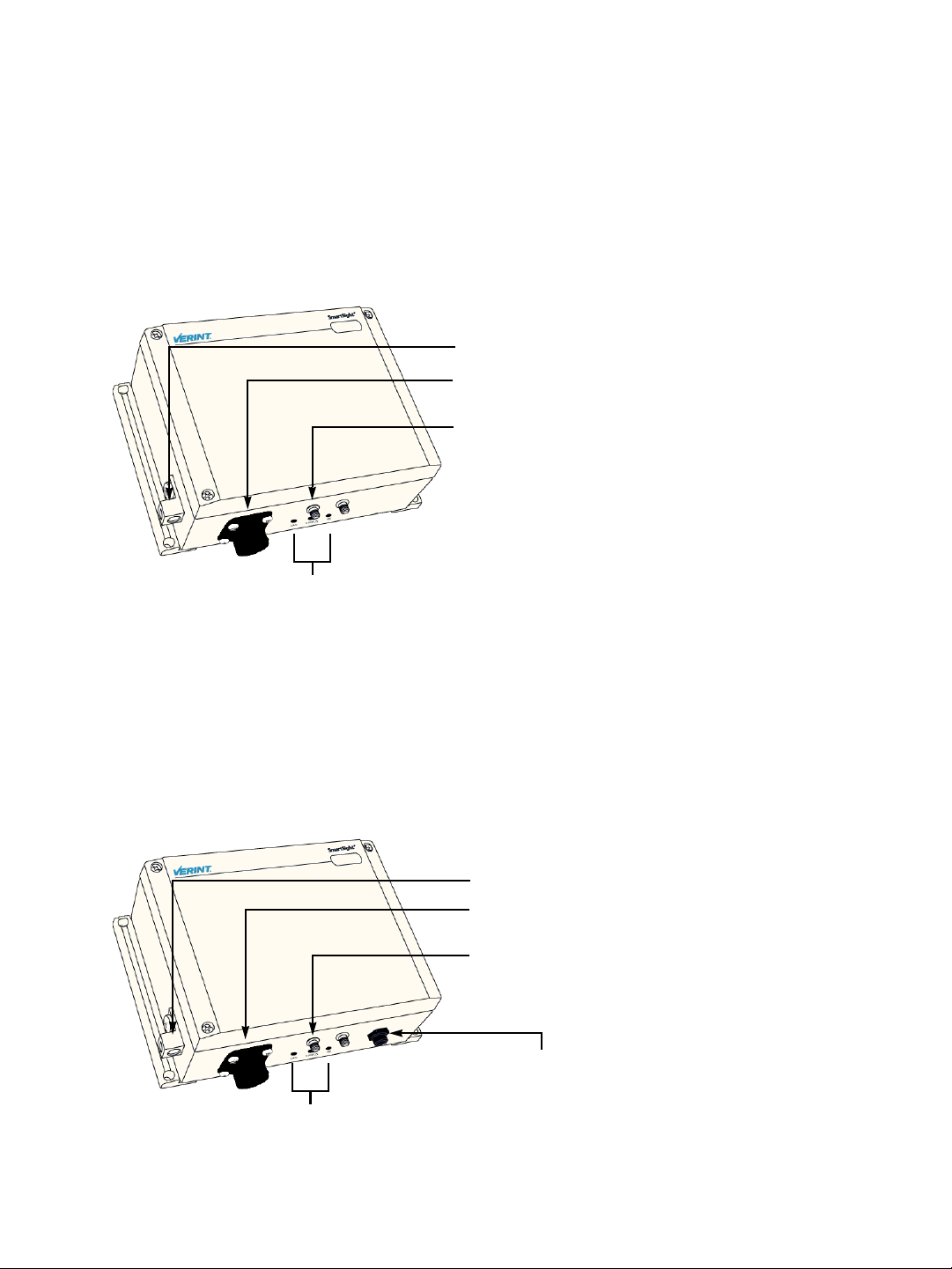
S3100
The device underside integrates:
A power and Ethernet connector
Three LEDs
A ground lug
Two female antenna connectors (the auxiliary connector is for future development)
Ground lug
Power (48V DC) and Ethernet connector
Main antenna connector
LEDs
S3100-BR and S3100-RP
The device underside integrates:
An Ethernet connector
Three LEDs
A ground lug
Two female antenna connectors (the auxiliary connector is for future development)
A 2-pin 24V AC power connector
Ground lug
Ethernet connector
Main antenna connector
24V AC connector
LEDs
4 Verint Video Intelligence Solutions

System and RF Planning
To allow optimal configuration, you must properly plan your network, especially
configuration layout and RF (radio frequency). Pla n ning is e specially r equired if y o u wan t
to install many systems in the same area, in order to prevent radio interference
between the colocated devices and to select the appropriate antennas. In all cases,
follow the recognized RF installation practices.
Verint Video Intelligence Solutions 5

2: System and RF Planning
Available Frequency Bands and Channels
The S3100 supports communications in the following frequency bands, in North America
and Europe:
2.4 GHz OFDM, also known as 802.11g
4.9 GHz OFDM, a public safety band available in North America only
5 GHz OFDM, also known as 802.11a
2.4 GHz Band
The 2.4 GHz band provides 11 channels in North America and 13 in Europe. In these two
regions, only channels 1, 6, and 11 are independent (that is, non-overlapping). All these
channels are for indoor or outdoor use. The center frequencies of the channels are:
Channel Frequency (GHz) Channel Frequency (GHz)
1 2.412 8 2.447
2 2.417 9 2.452
3 2.422 10 2.457
4 2.427 11 2.462
5 2.432 12 2.467 (Europe only)
6 2.437 13 2.472 (Europe only)
7 2.442
4.9 GHz Band
The 4.9 GHz band is a licensed band for entities providing public safety services focused on
the protection of life, health, or property in North America. This band provides license
holders with an interference-free, secure channel for robust and secure broadband
technologies, including wireless video surveillance systems.
For more detailed information concerning the regulations governing licensing and use of
frequencies in the 4.9 GHz band, see Subpart Y of the FCC document, Memorandum
Opinion and Order and Third Report and Order at:
http://hraunfoss.fcc.gov/edocs_public/attachmatch/FCC-03-99A1.pdf
The 4.9 GHz band has a width of 50 MHz (4940 to 4990 MHz). Since the standard channel
width is 20 MHz, only two independent channels can co-exist in the band. However, the
S3100 supports channel fragmentation, allowing narrower channels of 5 MHz and 10 MHz.
You can have up to four independent channels with a 10 MHz width, and up to 10 with a
5 MHz width. All these channels are for indoor or outdoor use. For more information about
channel fragmentation, see page 45.
6 Verint Video Intelligence Solutions

Nextiva S3100 Series User Guide
The available channels are:
Channel Frequency (GHz) Channel width
3 4.9425 5 MHz
6 4.9475 5 MHz
7 4.9525 5 MHz or 10 MHz
7 4.950 20 MHz
8 4.9575 5 MHz
9 4.9625 5 MHz or 10 MHz
10 4.9675 5 MHz
11 4.9725 5 MHz or 10 MHz
11 4.970 20 MHz
12 4.9775 5 MHz
13 4.9825 5 MHz or 10 MHz
16 4.9875 5 MHz
5 GHz Band
In the 5 GHz band, the number of available channels and sub-bands vary depending on the
country of operation.
Most European countries adhere to the DFS (Dynamic Frequency Selection) and TPC
(Transmit Power Control) regulations established by the European Telecommunications
Standards Institute (ETSI); these regulations apply to the 5 GHz frequency band only. To
know which bands are available in your country of operation and whether your country
adheres to DFS and TPC, refer to the Wireless Frequency Plan document located on the
Verint Video Intelligence Solutions extranet (Technical Support, then Downloads, then
Utilities and Tools).
In North America, five channels are available in the 5 GHz band, all independent and for
indoor or outdoor use. The center frequencies of these channels are:
Channel Frequency (GHz)
149 5.745
153 5.765
157 5.785
161 5.805
165 5.825
In Europe, the 11 independent channels, for indoor or outdoor use, are:
Channel Frequency (GHz) Channel Frequency (GHz)
100 5.50 124 5.62
104 5.52 128 5.64
108 5.54 132 5.66
112 5.56 136 5.68
116 5.58 140 5.70
120 5.60
Verint Video Intelligence Solutions 7
2: System and RF Planning
Wireless Cells
A wireless network is designed such that information can travel back and forth between two
points without the need for wires. Wireless devices are grouped into wireless cells. The
devices in a cell communicate together on the same frequency channel and share the same
wireless passkey (described on page 46).
Roles
An S3100 can have two MAC (Media Access Control) roles, according to its function in the
wireless cell: master or slave. The other wireless devices (S1100, S1100w) that are
connected to S3100 devices are clients. Clients always connect to a master S3100.
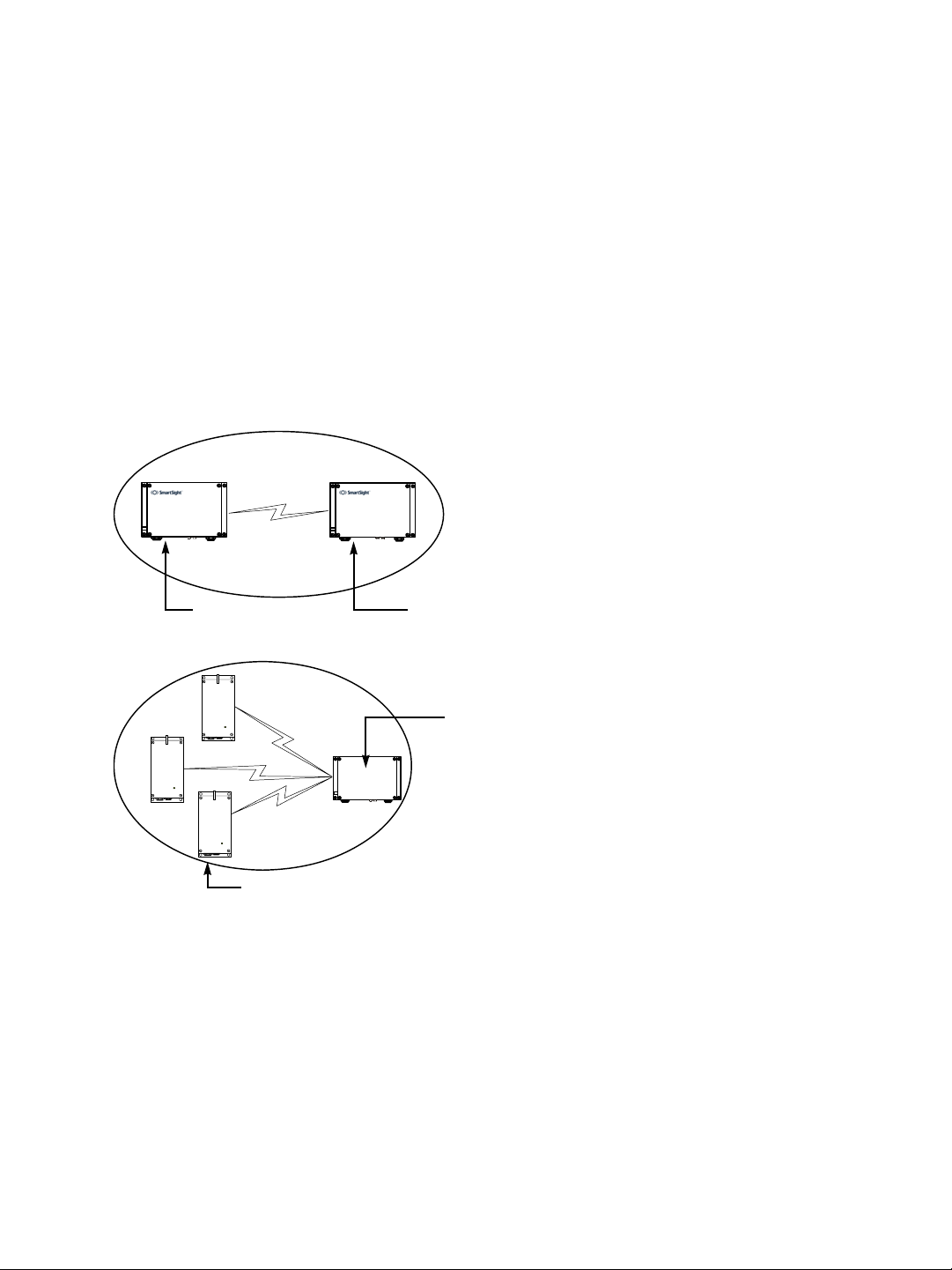
In this first example of a wireless cell, two S3100 devices, a master and a slave, form a
wireless bridge:
Slave
The second example shows three wireless clients associated to an S3100 master device:
S3100
Wireless clients
You can colocate many wireless cells if you respect certain conditions (see page 20).
Master
Master
Compatibility Issues
When planning your wireless systems, you need to take into account the firmware versions
of the involved devices. It is recommended that the S3100 devices ha ve the same firmware
versions as their associated slaves and clients; however, from version 2.60 and up, the
devices are fully compatible (for example, an S3100 at version 3.20 with an S1100w at
version 3.60).
8 Verint Video Intelligence Solutions
Nextiva S3100 Series User Guide
In a wireless cell involving S1100w transmitters, the order in which you configure the
devices (either the first time or later when they are installed in the field) or update their
firmware is critical if you do not want to lose access to them. You should then:
1. Update or configure the devices starting with the farthest (in terms of number of RF
hops) from the computer running the upgrade procedure.
2. One step at a time, get closer to the host computer.
In a point-to-point repeater, you should:
1. Update the firmware of all S1100 pairs, starting with the remote device.
2. Change the IP address of the computer running SConfigurator (see page 37).
3. Update the firmware of the two S3100 devices.
For example, consider the following wireless cell:
S1100w 1
S3100 3 S3100 2
S3100 1
S1100w 2
You should update or configure the devices in the following order:
1. S1100w 1—You then lose contact with S1100w 1.
2. S1100w 2—You then lose contact with S1100w 2.
3. S3100 1—You can then reach all devices.
4. S3100 2—You then lose contact will all devices except master S3100 3.
5. S3100 3—You can then reach all devices.
For the complete firmware update procedure, refer to the SConfigurator User Guide.
Video Bit Rate and Data Throughput
You can connect up to 16 client and 7 slave devices to a master S3100 in a wireless cell.
However, video quality, frame rate, and system layout can limit the number of devices that
a single master device can support.
Verint Video Intelligence Solutions 9
2: System and RF Planning
Each time multiple client or slave devices are connected to a master S3100, the available
bandwidth is divided equally between the connections. In the following example, two
S1100w clients and one slave S3100 connected to a master on a 6 Mbps link each have
2 Mbps throughput.
S3100S3100
S3100
Note: In that context, you must ensure that all devices connected to a slave S3100 do not
require more than the available bandwidth. Otherwise video packets may be lost.
Furthermore, video quality and frame rate influence the required data throughput.
Therefore, you need to carefully plan the number of cameras that will work on a link.
The following figures were measured in typical setup situations. They may vary depending
on your configuration. The total data throughput in a unidirectional UDP link setup varies
depending on two factors:
The MAC protocol. For more information about SPCF and SDCF, see page 13.
The frequency channel width: 20 MHz in all available bands, or 5 MHz and 10 MHz in
the 4.9 GHz frequency band.
SPCF
The throughput for a 20 MHz channel for the SPCF protocol is:
Physical bit rate Throughput for a 3 mile
(5 km) distance
6 Mbps 3.5 Mbps 3.4 Mbps 3.3 Mbps
9 Mbps 4.7 Mbps 4.5 Mbps 4.4 Mbps
12 Mbps 5.6 Mbps 5.4 Mbps 5.2 Mbps
18 Mbps 7.0 Mbps 6.6 Mbps 6.3 Mbps
24 Mbps 8.1 Mbps 7.5 Mbps 7.1 Mbps
36 Mbps 9.1 Mbps 8.6 Mbps 8.1 Mbps
48 Mbps 10.0 Mbps 9.3 Mbps 8.7 Mbps
54 Mbps 10.1 Mbps 9.5 Mbps 9.0 Mbps
Throughput for a
9.3 mile (15 km)
distance
Throughput for a
15.5 mile (25 km)
distance
10 Verint Video Intelligence Solutions

The throughput for a 10 MHz channel for the SPCF protocol is:
Nextiva S3100 Series User Guide
Physical bit rate Throughput for a 3 mile
(5 km) distance
3 Mbps 2.0 Mbps 1.9 Mbps 1.9 Mbps
4.5 Mbps 2.8 Mbps 2.7 Mbps 2.7 Mbps
6 Mbps 3.5 Mbps 3.4 Mbps 3.3 Mbps
9 Mbps 4.5 Mbps 4.4 Mbps 4.3 Mbps
12 Mbps 5.4 Mbps 5.1 Mbps 5.0 Mbps
18 Mbps 6.7 Mbps 6.3 Mbps 6.0 Mbps
24 Mbps 7.4 Mbps 7.1 Mbps 6.8 Mbps
27 Mbps 7.7 Mbps 7.4 Mbps 7.0 Mbps
Throughput for a
9.3 mile (15 km)
distance
Throughput for a
15.5 mile (25 km)
distance
The throughput for a 5 MHz channel for the SPCF protocol is:
Physical bit rate Throughput for a 3 mile
(5 km) distance
1.5 Mbps 1.1 Mbps 1.1 Mbps 1.1 Mbps
2.25 Mbps 1.5 Mbps 1.5 Mbps 1.5 Mbps
3 Mbps 1.9 Mbps 1.9 Mbps 1.8 Mbps
4.5 Mbps 2.6 Mbps 2.6 Mbps 2.5 Mbps
6 Mbps 3.2 Mbps 3.2 Mbps 3.1 Mbps
9 Mbps 4.2 Mbps 4.1 Mbps 3.9 Mbps
12 Mbps 4.9 Mbps 4.7 Mbps 4.6 Mbps
13.5 Mbps 5.1 Mbps 5.0 Mbps 4.8 Mbps
Throughput for a
9.3 mile (15 km)
distance
Throughput for a
15.5 mile (25 km)
distance
SDCF
The throughput for a 20 MHz channel for the SDCF protocol is:
Physical bit rate Throughput for a 3 mile
(5 km) distance
6 Mbps 4.5 Mbps 4.2 Mbps 4.0 Mbps
9 Mbps 6.3 Mbps 6.1 Mbps 5.3 Mbps
12 Mbps 7.8 Mbps 7.6 Mbps 6.7 Mbps
18 Mbps 10.5 Mbps 10.1 Mbps 8.4 Mbps
24 Mbps 12.7 Mbps 12.2 Mbps 9.8 Mbps
36 Mbps 15.9 Mbps 15.0 Mbps 11.7 Mbps
48 Mbps 17.9 Mbps 16.5 Mbps 12.7 Mbps
54 Mbps 18.9 Mbps 17.7 Mbps 13.2 Mbps
The throughput for a 10 MHz channel for the SDCF protocol is:
Physical bit rate Throughput for a 3 mile
(5 km) distance
3 Mbps 2.3 Mbps 2.3 Mbps 2.2 Mbps
4.5 Mbps 3.4 Mbps 3.2 Mbps 3.1 Mbps
Verint Video Intelligence Solutions 11
Throughput for a
9.3 mile (15 km)
distance
Throughput for a
9.3 mile (15 km)
distance
Throughput for a
15.5 mile (25 km)
distance
Throughput for a
15.5 mile (25 km)
distance

2: System and RF Planning
Physical bit rate Throughput for a 3 mile
(5 km) distance
6 Mbps 4.3 Mbps 4.1 Mbps 3.9 Mbps
9 Mbps 6.0 Mbps 5.6 Mbps 5.2 Mbps
12 Mbps 7.5 Mbps 6.9 Mbps 6.3 Mbps
18 Mbps 9.9 Mbps 8.9 Mbps 7.8 Mbps
24 Mbps 11.8 Mbps 10.3 Mbps 8.9 Mbps
27 Mbps 12.6 Mbps 10.9 Mbps 9.5 Mbps
Throughput for a
9.3 mile (15 km)
distance
Throughput for a
15.5 mile (25 km)
distance
The throughput for a 5 MHz channel for the SDCF protocol is:
Physical bit rate Throughput for a 3 mile
(5 km) distance
1.5 Mbps 1.2 Mbps 1.2 Mbps 1.1 Mbps
2.25 Mbps 1.7 Mbps 1.7 Mbps 1.7 Mbps
3 Mbps 2.3 Mbps 2.2 Mbps 2.1 Mbps
4.5 Mbps 3.2 Mbps 3.0 Mbps 2.9 Mbps
6 Mbps 4.1 Mbps 3.8 Mbps 3.7 Mbps
9 Mbps 5.5 Mbps 5.1 Mbps 4.8 Mbps
12 Mbps 6.7 Mbps 6.1 Mbps 5.6 Mbps
13.5 Mbps 7.1 Mbps 6.5 Mbps 5.9 Mbps
Throughput for a
9.3 mile (15 km)
distance
Throughput for a
15.5 mile (25 km)
distance
The S3100 automatically adjusts the transmission speed with the current RF conditions.
For the bit rate requirements of the edge devices to which the cameras are connected,
consult the Bit Rate Settings for Video Servers document located on the Verint Video
Intelligence Solutions extranet (Technical Support, then Downloads, then Utilities and
Tools).
System Planning
The grouping of devices in each wireless cell is determined by their respective locations
with respect to one another and by the available S3100 devices. As a rule of thumb, each
client or slave device must have a clear RF line of sight with its master device within each
cell. However, the client and slave devices can be completely hidden from one another. For
more information about the RF line of sight, see page 25.
MAC Protocols
Depending on the type of applications, an S3100 device uses one of the two proprietary
MAC protocols that solve problems inherent to 802.11 wireless networking products:
The SPCF (SmartSight Point Coordination Function) protocol resolves the “hidden
node,” quality of service, range, and security problems. SPCF is used in access point
applications and in repeater contexts. With this protocol, a master S3100 has total
control over the radio frequency used; therefore, in an RF line-of-sight context, you
cannot install two cells sharing the same frequency channel.
12 Verint Video Intelligence Solutions
Nextiva S3100 Series User Guide
You use the SDCF (SmartSight Distributed Coordination Function) protocol in
point-to-point systems with a high volume of video transmission—typically ov er long
distances or when a remote site is hard to reach—and in wireless bridge applications.
SDCF optimizes the RF link by providing more data throughput. It also resolves the
range and security problems of the 802.11 standard. However, SDCF does not manage
the hidden node issue.
These two protocols are designed to work with Nextiva devices; they cannot work with
wireless devices from other vendors.
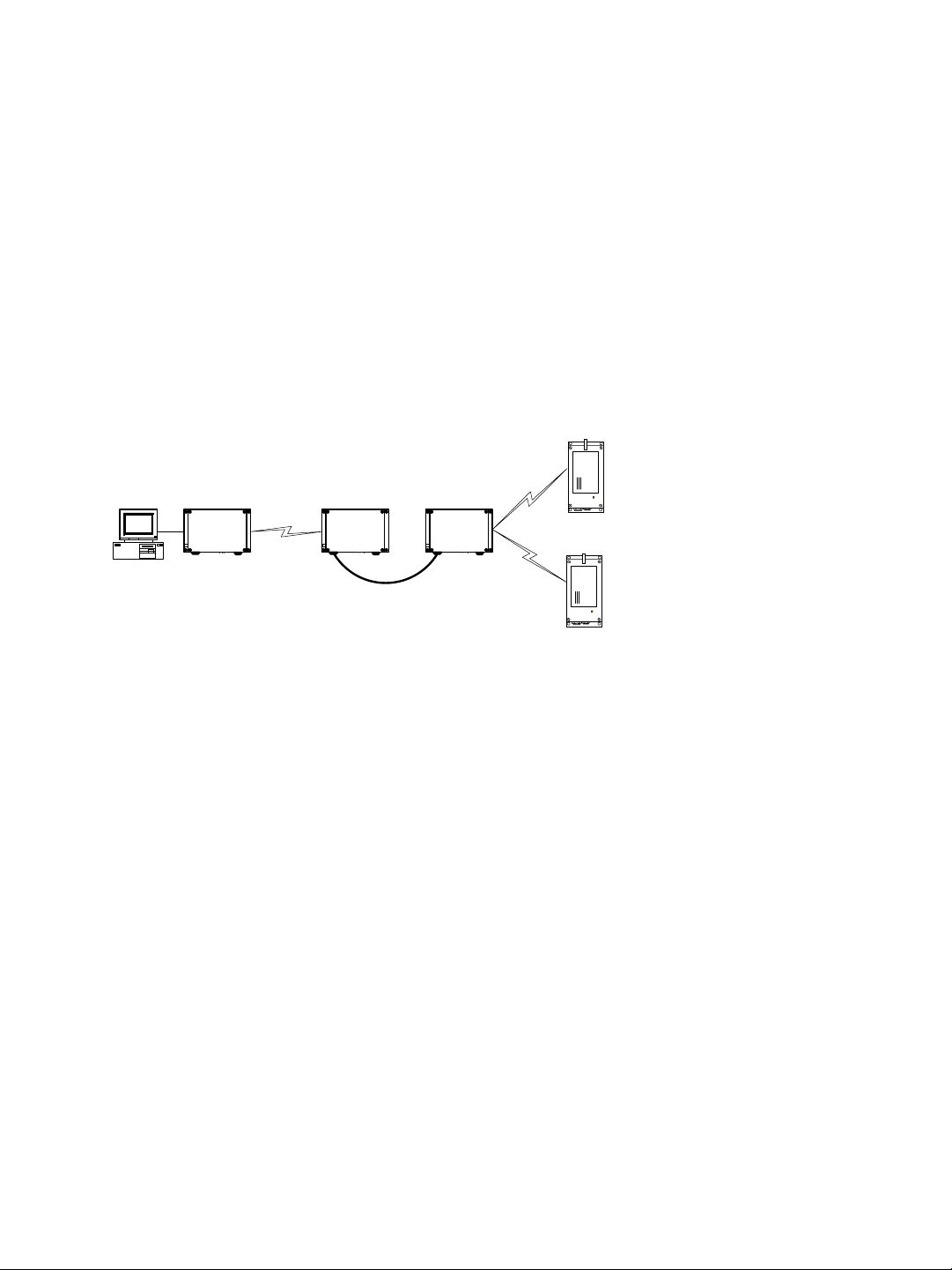
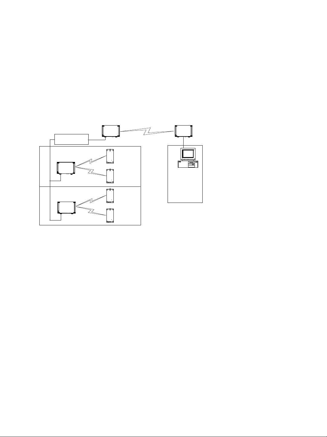
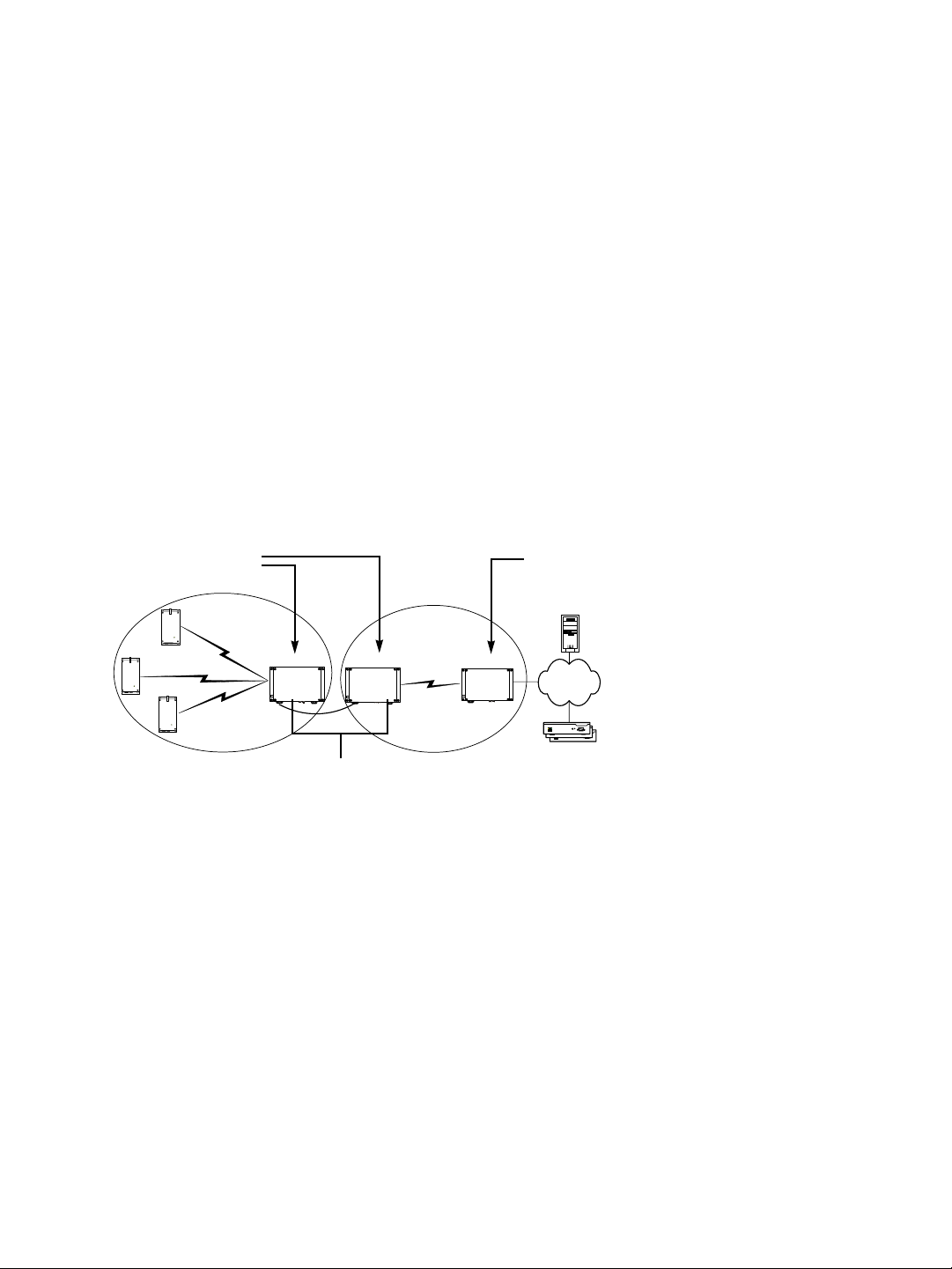
Here is a typical context of use showing the two protocols. A access point system is
installed on every floor of a multistorey parking building. The surveillance station is in
another building. The SDCF cell acts as a wireless bridge between the two sites.
Ethernet switch
Master
Master
Slave
SDCF
SPCF
SPCF
Master
TPC
If the country of operation of the S3100 device requires conformity to the TPC (Transmit
Power Control) regulations, the transmission power of its radio is automatically reduced by
3 dB before leaving the Verint factory. However, in case of a weak wireless link (that is, a
link with an RF margin of less than 15 dB), you have the opportunity to use the maximum
transmission power (see page 63).
DFS
To follow the DFS (Dynamic Frequency Selection) regulations specified by ETSI for the
selected country, it is the master device that performs the tasks relative to frequency
channel selection and radar detection. In other words, you cannot choose the frequency
channel on which the edge device will run.
The automatic selection of the frequency channel limits the number and the configuration of
the wireless cells. Furthermore, when colocating many cells, all masters must “see” each
other.
Note: DFS is required only in the 5 GHz band.
You should start the master first, then power the client or slave when the other device is in
normal operation.
Verint Video Intelligence Solutions 13
2: System and RF Planning
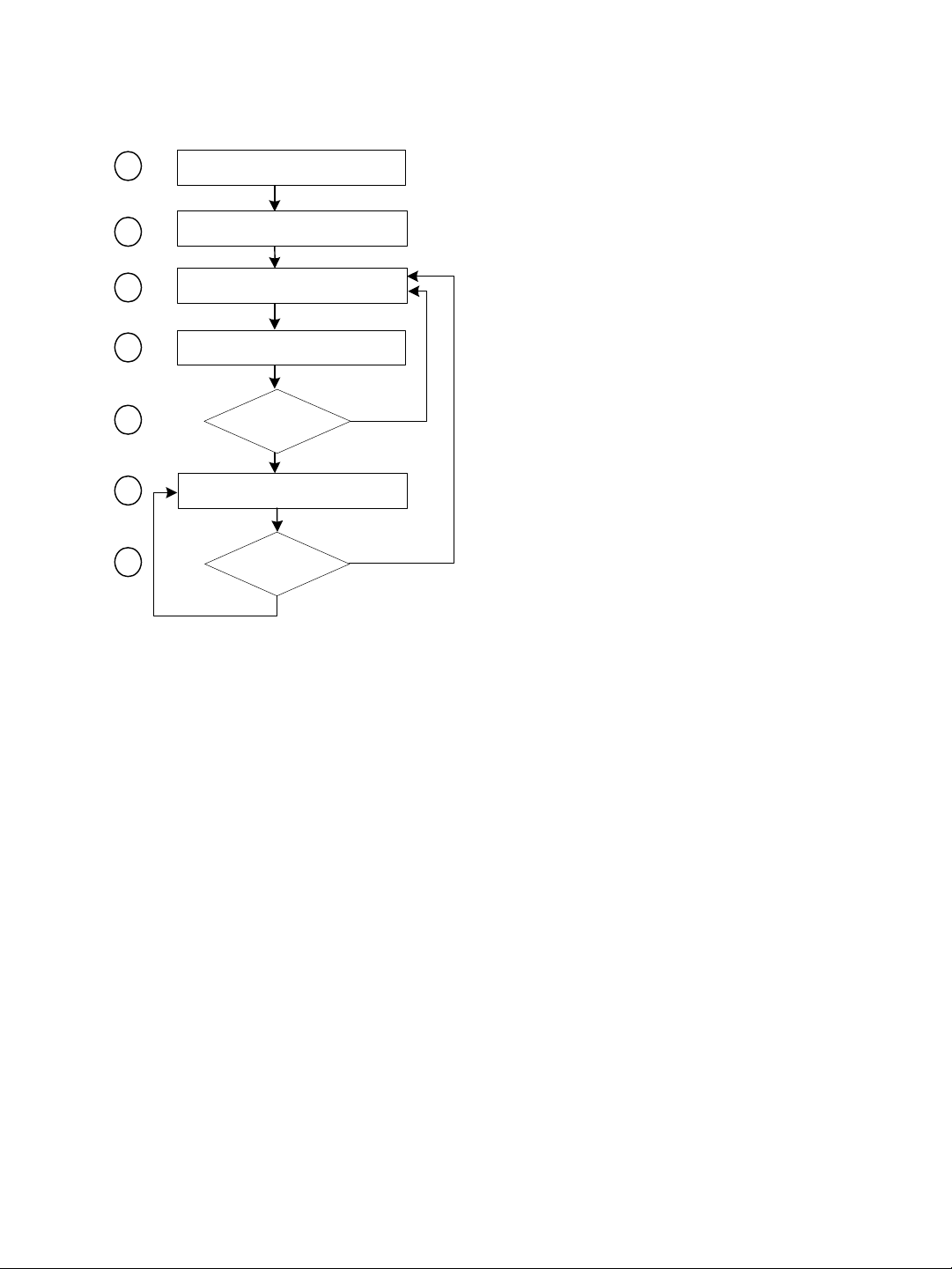
A master device in DFS mode goes through the following sequence when booting up:
1
2
3
4
5
6
7
Unit initialization (3 seconds)
Starting order delay (0-15 minutes)
Frequency scan (10-20 seconds)
Radar detection (60 seconds)
Radar detected?
no
Normal operation
Radar detected?
no
yes
yes
1. The device goes through the standard startup procedure.
2. The starting order delay ensures that colocated masters will not select a frequency
channel at the same time, therefore minimizing the possibility that they choose the
same one. For more information about the starting order, see page 64.
3. The device scans the available frequencies (based on the selected country) and
automatically selects a channel. In the selection process, channels already used by
colocated masters will be discarded at first.
4. The device listens for 60 seconds on the selected channel to detect possible radar
interference.
5. If a radar is detected on the channel, the device returns to the scan process. Otherwise,
it continues its bootup procedure.
6. The device runs normally.
7. If a radar is detected, the device immediately goes back to the scan process to select
another channel.
14 Verint Video Intelligence Solutions
Nextiva S3100 Series User Guide
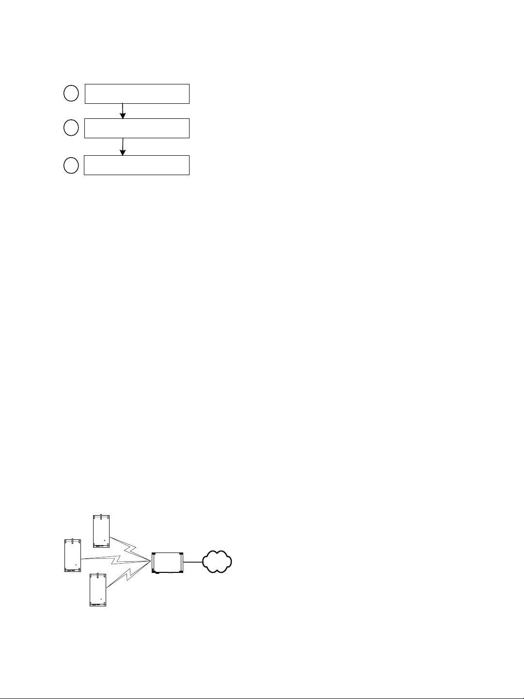
The boot sequence of client or slave devices is:
Unit initialization (3 seconds)
1
Roaming (2-25 seconds)
2
Normal operation
3
1. The device goes through the standard startup procedure.
2. The device roams through the channels in the available frequency bands to locate its
master.
3. When the master is located, the client or slave device runs normally on the selected
frequency channel.
Application Types
The S3100 devices are used in many types of applications, including:
Access point—One S3100 device linking multiple S1100w transmitters to a LAN (the
S3100 model)
Point-to-point repeater— Two S3100 devices acting as a range extender for one or many
pairs of S1100 transmitters (the S3100-RP model)
Point-to-multipoint repeater—Two S3100 devices acting as a range extender for
multiple S1100w transmitters (the S3100-RP model)
Wireless bridge—Two S3100 devices linking two networks, wired or wireless (the
S3100-BR model)
Wireless bridge repeater—Two S3100 devices acting as a range extender for a wireless
bridge (the S3100-RP model)
Access Point
An access point application is a wireless cell made up of an S3100 device (the S3100
product code, called the master) and several S1100w transmitters (the clients). The MAC
protocol for the master device is SPCF. Here is a typical access point system:
S1100w
S3100
Verint Video Intelligence Solutions 15
2: System and RF Planning
To install a single wireless cell made up of three S1100w transmitters and one S3100, you
need to:
1. Assign the same wireless passkey to the S1100w and S3100 devices.
2. In a non-DFS context, assign a frequency channel to the S3100. In a DFS context, the
master device will automatically select a channel.
The associated S1100w transmitters will automatically use their master’s channel.
3. Install the S1100w transmitters such that each one has a clear RF line of sight with the
S3100 device.
For the complete configuration and installation procedures, see page 31.
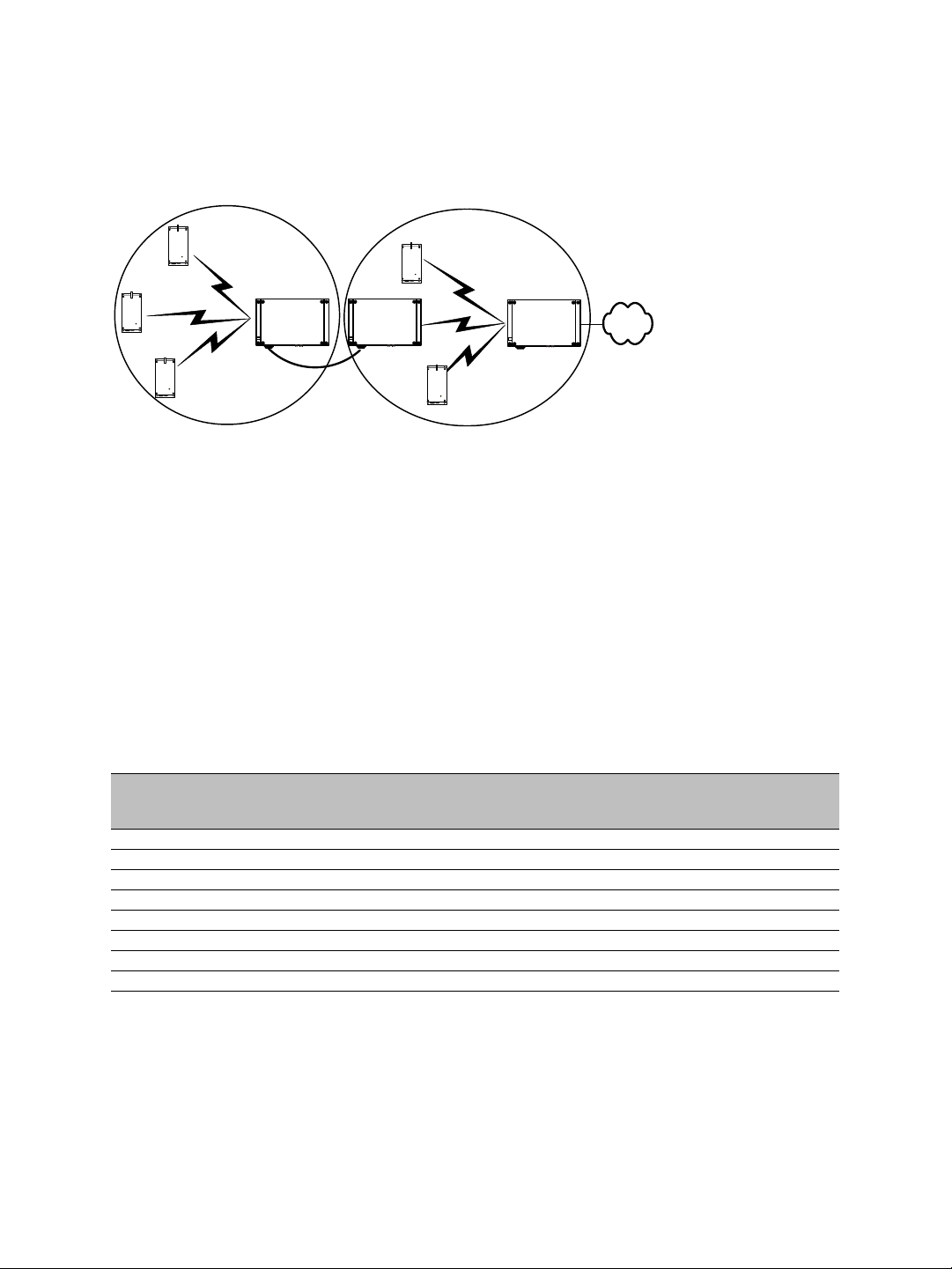
Point-to-Multipoint Repeater
A point-to-multipoint repeater is used as a range extender for wireless links, when you
need a device to retransmit the signals coming from S1100w transmitters towards the
Ethernet LAN. A typical context is when you cannot obtain an RF line of sight between the
transmitters and the S3100 connected to the wired LAN.
A point-to-multipoint repeater (the S3100-RP product code) is made up of two S3100
devices separated into two colocated cells. For example:
Master
Slave
Video
management
software
S3100 S3100S3100
Receivers
Repeater
To operate the two cells forming the repeater, you need to:
1. In each cell, assign the same wireless passkey to all the devices. The wireless passkey
must be different from that of the other cell.
2. Always connect the S1100w transmitters to a master S3100, never to a slave.
3. Set the MAC mode of the S3100 in Cell1 to SPCF.
4. Set the MAC mode of the two S3100 devices in Cell2 to SDCF.
5. In a non-DFS context, assign a frequency channel to the master S3100 device in each
cell. For better isolation, use different frequency bands.
6. In a DFS context, set a different starting order for each master S3100. Ensure that the
two masters see each other.
7. Install the S1100w and slave S3100 devices such that each one has a clear RF line of
sight with its associated master.
For the complete configuration and installation procedures, see page 32.
16 Verint Video Intelligence Solutions
Nextiva S3100 Series User Guide
Point-to-Point Repeater
A point-to-point repeater is used as a range extender for wireless links, when you need a
device to retransmit the signals coming from one or many S1100 transmitters to their
corresponding receivers. A typical context is when you cannot obtain an RF line of sight
between the transmitters and the receivers.
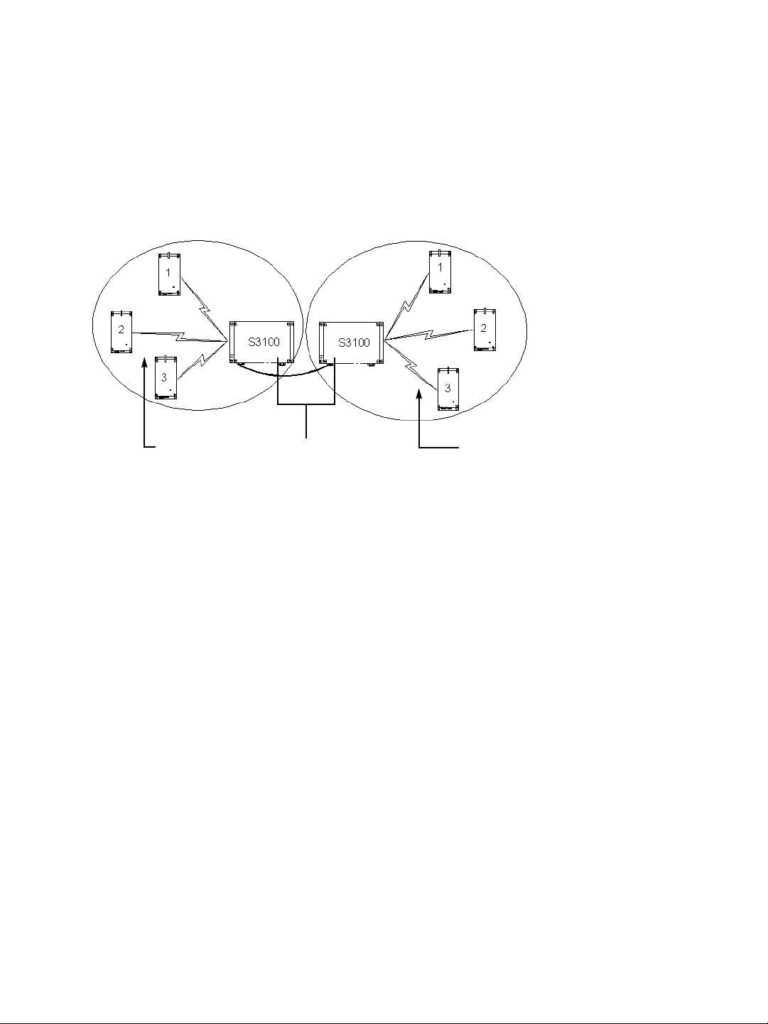
A point-to-point repeater (the S3100-RP product code) is made up of two master S3100
devices, separated into two colocated cells. For example, with three pairs of S1100 devices:
RepeaterTransmitters Receivers
To operate the two cells forming the repeater, you need to:
1. In each cell, assign the same wireless passkey to all the devices. The wireless passkey
must be different from that of the other cell.
2. Set the MAC mode of the two S3100 devices to SPCF.
3. In a non-DFS context, assign a frequency channel to the master S3100 device in each
cell. For better isolation, use different frequency bands.
4. In a DFS context, set a different starting order for each master S3100. Ensure that the
two masters see each other.
5. Install the S1100 devices such that each one has a clear RF line of sight with its
associated master.
For the complete configuration and installation procedures, see page 30.
Verint Video Intelligence Solutions 17
2: System and RF Planning
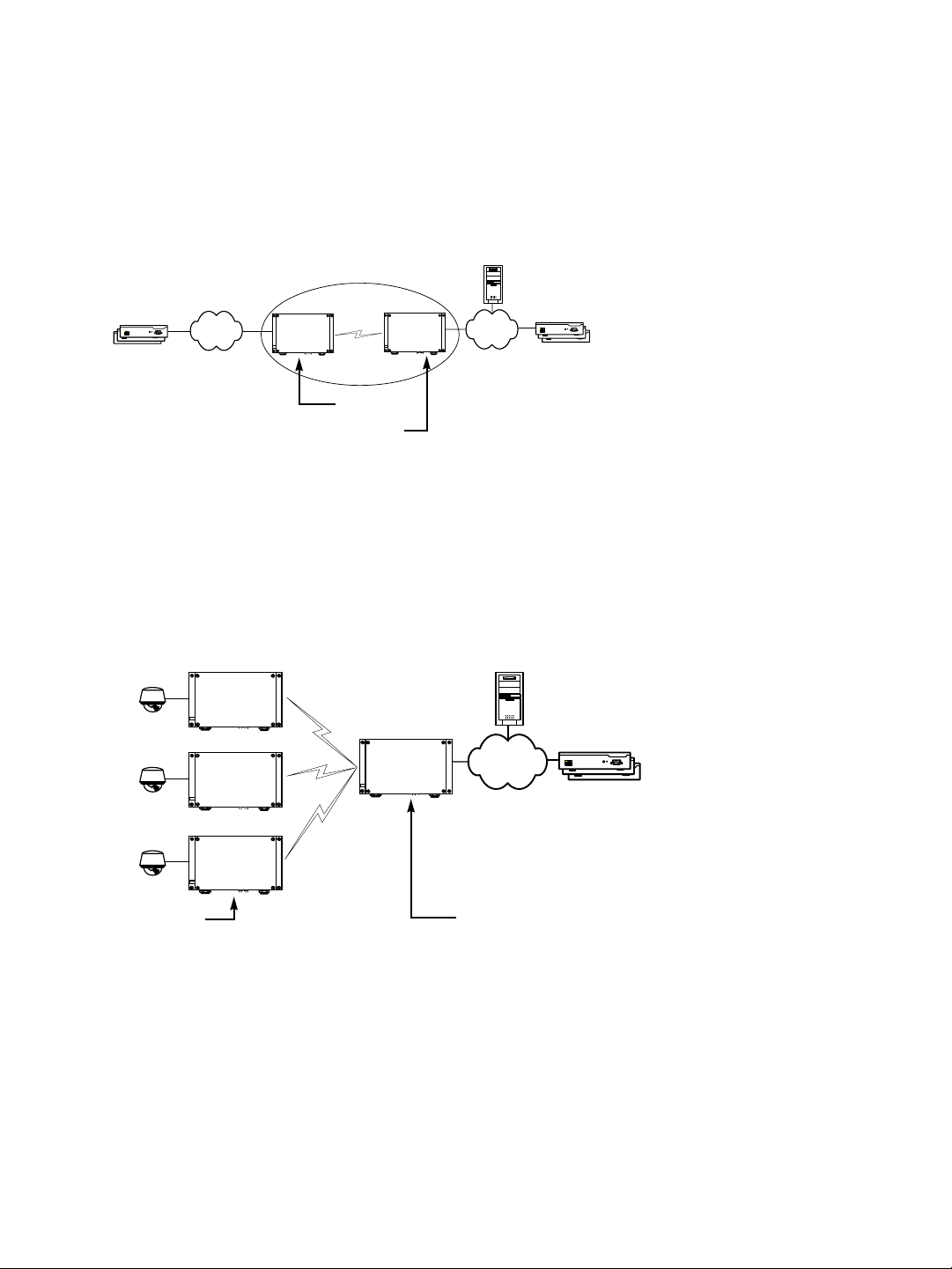
Wireless Bridge
You use two S3100 devices (the S3100-BR product code)—a master and a slave—to
transfer video surveillance data between two LANs when a wired connection is not av ailable
or too costly to install. For instance, a wireless bridge application can connect remote
S1900e-AS edge devices (the following illustration) or wireless devices without an RF line of
sight.
Transmitters Receivers
S3100
S3100
Slave
Master
To create a wireless bridge application, you need to:
1. Assign the same wireless passkey to the two S3100 devices.
2. In a non-DFS context, assign a frequency channel to the master S3100 device.
3. Set the MAC mode of the two S3100 devices to SDCF.
Video management
software
4. Install the S3100 devices such that there is a clear RF line of sight between the two
antennas.
You can also use the S3100-BR product in point-to-multipoint wireless bridges, to transmit
video coming from IP cameras:
IP camera
S3100
S3100
SPCF
S3100
SPCF
...
S3100
Slaves Master
All slaves (you can install up to seven of them) must be S3100-BR devices. The
configuration of such an application is very similar to that of a standard wireless bridge,
except that the MAC role of the devices is SPCF instead of SDCF.
For the complete configuration and installation procedures, see page 33.
SPCF
18 Verint Video Intelligence Solutions

Nextiva S3100 Series User Guide
Wireless Bridge Repeater
A wireless bridge repeater is used as a range extender to retransmit the signals exchanged
by the two devices forming a wireless bridge. A typical context is when you cannot obtain
an RF line of sight between the two devices forming the wireless bridge.
A wireless bridge repeater (the S3100-RP product code) is made up of two master devices,
separated into two colocated cells. For example:
Repeater
Video
management
Transmitters
softwa re
Receivers
S3100
To operate the two cells forming the repeater, you need to:
1. In each cell, assign the same wireless passkey to the two devices. The wireless passkey
must be different from that of the other cell.
2. Set the MAC mode of all four S3100 series devices to SDCF.
3. In a non-DFS context, assign a frequency channel to the master S3100 device in each
cell. For better isolation, use different frequency bands.
4. In a DFS context, set a different starting order for each master S3100. Ensure that the
two masters see each other.
5. Install the S3100 series devices such that each one has a clear RF line of sight with its
corresponding counterpart.
For the complete configuration and installation procedures, see page 34.
S3100 S3100 S3100
Slave (S3100-BR device)
Master (S3100-RP device)
Master (S3100-RP device)
Slave (S3100-BR device)
Verint Video Intelligence Solutions 19

2: System and RF Planning
Colocated Cells
You can operate many wireless cells in the same location, provided you follow guidelines
relative to frequency band and channel, distance, wireless passkey, and location.
Distance Limitations
The distance limitations between devices are:
The minimum distance between two devices is 3 feet (1 meter), regardless of the band
or channel used.
To avoid material damages, you must never power any two devices while their
antennas are facing one another with a distance of less than 10 feet (3 meters).
In an SDCF cell, if the maximum distance between two devices is longer than 6 miles
(10 km), you must adjust the maximum link distance parameter; for more information,
see page 64.
If using adjacent channels, see page 83 for the recommendations on the minimum
distances to respect.
To reduce radio interference possibilities between two adjacent frequency channels,
ensure that the maximum margin between the emission of the two wireless cells is
25 dB; for more information, see Appendix G on page 83.
General Guidelines
Regarding frequency channel, you cannot manually select one in the 5.40–5.725 GHz band
in Europe; for the detailed procedure, see page 22. In the 4.9 GHz and 5 GHz band in North
America and the 2.4 GHz band everywhere, the channel selection guidelines vary
depending on the MAC protocol:
When at least one SPCF cell is involved, you cannot use the same frequency channel.
Tw o SDCF cells can use the same frequency channel. They will share the available
bandwidth.
The wireless passkeys of colocated cells must be different from one another, regardless of
their MAC protocols or frequency channels.
4.9 GHz Band in North America
Depending on the channel width (20, 10, or 5 MHz), you can colocate 2, 4, or 10 wireless
cells respectively. For the available channels in each of the three scenarios, see page 7.
The following example presents three wireless cells with 10-MHz channels. To install such a
system, you have to:
1. In each cell, assign the same wireless passkey to the S1100w transmitters and the
S3100 access point. The wireless passkey must be different from that of the other cells.
20 Verint Video Intelligence Solutions

Nextiva S3100 Series User Guide
2. Assign a different frequency channel to each S3100 device; the associated S1100w
devices will automatically use their master’s channel:
Device Cell Channel Wireless Passkey
S3100_A A 7 ertynmbvcxzapoiu
S1100w_A1 A 7 ertynmbvcxzapoiu
S1100w_A2 A 7 ertynmbvcxzapoiu
S1100w_A3 A 7 ertynmbvcxzapoiu
S3100_B B 13 PUK98rewq4123qzx
S1100w_B1 B 13 PUK98rewq4123qzx
S1100w_B2 B 13 PUK98rewq4123qzx
S1100w_B3 B 13 PUK98rewq4123qzx
S3100_C C 11 987123jkl456wert
S1100w_C1 C 11 987123jkl456wert
S1100w_C2 C 11 987123jkl456wert
S1100w_C3 C 11 987123jkl456wert
3. In each cell, install the S1100w devices such that each one has a clear RF line of sight
with its associated S3100 access point.
This application can be illustrated this way, where the three cells are in the same location:
B
C
A
5 GHz Band in North America and 2.4 GHz Band
In the 2.4 GHz band in North America and Europe, you can use the three independent
channels (channels 1, 6, and 11) to colocate wireless cells. In the 5 GHz band, all channels
are independent.
A typical colocation example is three access point applications, each one made up of three
S1100w transmitters and one S3100. To install such a system, you need to:
1. In each cell, assign the same wireless passkey to the S1100w transmitters and the
S3100 device. The wireless passkey must be different from that of the other cells.
Verint Video Intelligence Solutions 21

2: System and RF Planning
2. Assign a different frequency channel to each S3100 master device; the associated
S1100w transmitters will automatically use their master’s channel. For example:
Device Cell Channel Wireless Passkey
S3100_A A 149 ertynmbvcxzapoiu
S1100w_A1 A 149 ertynmbvcxzapoiu
S1100w_A2 A 149 ertynmbvcxzapoiu
S1100w_A3 A 149 ertynmbvcxzapoiu
S3100_B B 165 PUK98rewq4123qzx
S1100w_B1 B 165 PUK98rewq4123qzx
S1100w_B2 B 165 PUK98rewq4123qzx
S1100w_B3 B 165 PUK98rewq4123qzx
S3100_C C 157 987123jkl456wert
S1100w_C1 C 157 987123jkl456wert
S1100w_C2 C 157 987123jkl456wert
S1100w_C3 C 157 987123jkl456wert
3. In each cell, install the S1100w transmitters such that each one has a clear RF line of
sight with its associated S3100 device.
This application can be illustrated this way, where the three cells are in the same location:
B
C
A
Installing more than three cells in the 2.4 GHz band or more than nine cells in the 5 GHz
band requires more RF planning. In such a context, you should contact the Verint Video
Intelligence Solutions project engineering group for assistance.
5 GHz Band in Europe
The maximum number of colocated cells corresponds to the number of channels in the
available frequency bands that can be used outdoors. For instance, in most countries of
Western Europe, you can have up to 11 colocated cells in the 5.40–5.725 GHz band.
However, because the master devices must see each other in a DFS context, the variety of
supported setups is limited.
22 Verint Video Intelligence Solutions

Nextiva S3100 Series User Guide
In this context, you can easily install up to five cells. By respecting the following steps, you
can assume that the cells will not share the same frequency channel, making the complete
bandwidth available for each one. You have to:
1. Assign a different wireless passkey to each cell.
2. Ensure that all S3100 masters “see” one another. For the procedure, see Appendix F on
page 79.
3. Position the devices so that there is at least 3 feet (1 meter) between each antenna.
4. In each master device, set a different starting order: 1 for the first device, 2 for the
device next to it, 3 for the third one, and so on.
Installing more than five cells in the 5.40–5.725 GHz band requires the use of adjacent
channels. This situation demands greater distances between the antennas to reduce
potential radio interference. Therefore, you should contact the Verint Video Intelligence
Solutions project engineering group for assistance.
Supported Setups
The following colocated systems are supported in the 5.40–5.725 GHz band:
A point-to-point repeater for one or more pairs of S1100 devices, with or without
hidden nodes. Both master devices see each other.
Repeater
T wo access point applications, in which the transmitters from one system do not see the
transmitters from the other cell. Both master devices see each other.
S3100 S3100
Verint Video Intelligence Solutions 23

2: System and RF Planning
A point-to-multipoint repeater. Both master devices see each other.
Master
S3100 S3100S3100
Slave
Video
management
software
Receivers
Repeater
Unsupported Setups
You cannot install the following colocated systems in the 5 GHz band in Europe:
A point-to-point repeater with a point-to-point link. In this setup, two masters do not
see each other, S3100 2 and S1100-R 2, while the two receivers do.
S3100 2S3100 1
S1100-T 2S1100-R 2S1100-T 1 S1100-R 1
Repeater Point-to-point
Access point applications with hidden masters. In this context, the two S3100 masters
do not see each other, while transmitters 2 and 3 do.
2
1
S3100 S3100
24 Verint Video Intelligence Solutions
3
4

Nextiva S3100 Series User Guide
Multiple point-to-point repeaters. The S3100 2 and S3100 3 masters do not see each
other, while the two receivers do.
S1100-T 1 S1100-R 2
S3100 1 S3100 4S3100 3
Repeater Repeater
S3100 2
S1100-R 1
S1100-T 2
RF Planning
Successful operation of a wireless link depends on proper RF path planning and antenna
installation. You have to install the devices in such a way that there is a clear RF line of
sight between the two antennas.
Location Evaluation
The path between the two antennas must be free of obstacles that could disturb
propagation. For very short link distances—less than 500 feet (152 meters)—you may be
able to establish a working link despite partial path obstruction. However, radio waves will
be in part absorbed and in part diffracted by the obstacles, therefore affecting link
reliability. Because the reliability of such an installation is highly unpredictable, Verint does
not recommend it. A path free of any obstacle is called an RF line-of-sight path.
To establis h an RF line-of-sight path, you must take into account the beam width of the
radio signal transmitted between the two antennas. This beam width is an elliptical area
immediately surrounding the visual line of sight. It varies in thickness depending on the
length of the line of sight; the longer the length, the thicker the beam width becomes.
The region outlined by the signal beam width is known as the first Fresnel zone. The
Fresnel zone is always thicker at the mid-point between the two antennas. Therefore what
appears to be a perfect line-of-sight path between the base and a remote station may not
be adequate for a radio signal; this is the difference between “visual” and “RF” line of sight.
Visual line of sight First Fresnel zone (F1)
Verint Video Intelligence Solutions 25

2: System and RF Planning
In practice, it has been determined that a radio path can be considered an RF line-of-sight
path if it has a clear opening through 60% of the first Fresnel zone (or 0.6 F1). Here are
values for 0.6 F1 for various signal path distances and frequency bands:
Distance
(mi./km)
1 / 1.6 14 / 4.2 9.8 / 3.0 9.5 / 2.9 8.9 / 2.7 0
4 / 6.5 27 / 8.4 19.5 / 5.9 18.7 / 5.7 18 / 5.5 2 / 0.6
7 / 11.3 37 / 11 25.8 / 7.9 25 / 7.6 23.6 / 7.2 6 / 1.8
15 / 24 53 / 16 37.8 / 11.5 36.4 / 11.1 35 / 10.6 29 / 8.8
2.45 GHz
(feet/m)
4.9 GHz
(feet/m)
5.3 GHz
(feet/m)
5.8 GHz
(feet/m)
Earth curvature effect
(feet/m)
For distances under seven miles, the earth curvature effect is negligible. However, for
greater distances, you need to consider it in your calculations; for instance, for a 15-mile
link in the 2.4 GHz band, the two antennas must be located 82 feet higher than the highest
obstacle in the RF line of sight between them (that is, 53 feet for the Fresnel zone plus
29 feet for the earth curvature effect). For help, consult the Verint Video Intelligence
Solutions Support group.
A common problem encountered in the field and related to the 0.6 F1 clearance rule is
building obstruction. The proposed visual path may just barely clear a building but the RF
line of sight will not. In such a case, the signal will be partially absorbed and diffracted.
Increasing the height of the two antennas or the gain of the antennas are the only
alternatives to improve the link quality.
Note: At 2.4, 4.9, and 5 GHz, radio waves are highly attenuated by dense foliage. A link
established in the fall or winter season may be adversely affected in the spring and
summertime, if it is established below tree level.
Antenna Requirements
Verint offers many antennas to meet various distance requirements. You need to consider
many factors when choosing an antenna, including the distance to cover, the RF bit rate,
the radiated power (EIRP), and the frequency band. For systems located in North America
on the 5 GHz band, you can use the Wireless System Margin Calculator located on the
Verint Video Intelligence Solutions extranet (Technical Support, then Downloads, then
Utilities and Tools).
The combined transmission power of the device and antenna must not exceed the
maximum value established by your country’s regulations. To ensure that this maximum is
not exceeded, enter the gain of the chosen antenna in the CLI (Wireless Communication
menu) or SConfigurator (Wireless pane). The device will automatically take it into account
and adjust its own transmission power accordingly at startup.
Note: Connecting an antenna with a gain higher than the calculated value contravenes your
country’s regulations. It is your responsibility to ensure that you respect the
regulations in place. You can only use antennas certified by Verint.
26 Verint Video Intelligence Solutions

Nextiva S3100 Series User Guide
The maximum antenna gain supported to meet local regulations are:
Location Band Antenna gain Comment
Europe 2.4 GHz 8.5 dBi
5 GHz 13 dBi
North America 2.4 GHz 16 dBi
4.9 GHz 13 dBi To be used only with the S3100-49, S3100-BR-49,
and S3100-RP-49
5 GHz 19 dBi
The antennas certified by Verint are:
ANT- WP8-24/S: 8.5 dBi gain, 2.4 GHz band, 65° beamwidth, patch antenna with 3-foot
(1-meter) SMA-SMA cable
ANT-WP13-5x/S: 13 dBi gain, 5.25-5.85 GHz band, 40° beamwidth, patch antenna
SMA/F connector
ANT-WP13-49-5x/S: 13 dBi gain, 4.9-5.85 GHz band, 40° beamwidth, patch antenna
SMA/F connector
ANT- WP16-24/S: 16dBi gain, 2.4 GHz band, 27° beamwidth, patch antenna with 3-foot
(1-meter) SMA-N cable
ANT- WP19-5x/S: 19 dBi gain, 5.25-5.85 GHz band, 18° beamwidth, patch antenna with
3-foot (1-meter) SMA-N cable
Interference
In most countries, the 2.4 GHz band is not regulated by a government agency; this absence
of frequency coordination can result in interference between various systems. For instance,
if a link with an RF line of sight is subject to excessive video delay and very low frame rate
(or possibly breakdown of video images), it could be due to interference. Fortunately, you
have ways of adapting your setup to avoid interference:
RF channel selection—The S3100 has 11 or 13 channels to choose from. In case of
interference, it is recommended to change channel until you find a clean one.
Antenna selection—Replacement of the integrated antenna by a higher gain one can
significantly lower the interference from other radio systems. Replace the antenna if
switching channels does not correct the problem or if all channels must be used to
colocate several systems.
There should not be any interference in the 4.9 GHz band, since it is a licensed band with
limited usage to public safety.
The 5 GHz band is less cluttered than the 2.4 GHz band, resulting in less potential
interference from other wireless systems.
RF Exposure Considerations
In order to comply with the RF exposure requirements of CFR 47 part 15 in North America,
the devices must be installed in such a way as to allow a minimum separation distance of
12 inches (30 cm) between antennas and persons nearby.
Verint Video Intelligence Solutions 27

28 Verint Video Intelligence Solutions

Configuring and
Installing the Device
You can set up the S3100 devices for access point, repeater, or wireless bridge applications.
Verint Video Intelligence Solutions 29

2: Configuring and Installing the Device
Computer Requirements
The minimum hardware and software requirements for the host computer needed to
configure the edge device are:
An Ethernet network card
Windows 2000 Service Pack 2 or higher, or Windows XP Service Pack 2
Point-to-Point Repeater
A point-to-point repeater is a range extender for wireless links, when you need a device to
retransmit the signals coming from one or many S1100 transmitters to their corresponding
receivers. You use the S3100-RP (made up of two S3100 devices) to create this repeater.
RepeaterS3100_1 in Cell1 S3100_2 in Cell2
The steps required to prepare your devices for this type of application are:
1. Configuring the S1100 pairs in repeater mode. For the procedure, refer to the Nextiva
S1100 User Guide.
Warning: You must complete the configuration of the S1100 devices before powering
up an S3100 device.
2. Assembling the 24V DC power devices (see page 37).
3. Configuring the two S3100 devices, one at a time (see page 37). You need to shut
down the first device before configuring the second one.
The wireless parameters to apply are:
Parameter S3100_1 S3100_2
MAC mode SPCF SPCF
Role Master Master
Band Band1; if necessary in the 4.9 GHz
band, change the channel bandwidth
Channel In a non-DFS context: ChannelA In a non-DFS context: ChannelB
Bit rate N/A N/A
Starting order In a DFS context: 1 In a DFS context: 2
Wireless passkey Passkey1 common to all devices in
Cell1
Band1; if necessary in the 4.9 GHz
band, change the channel bandwidth
Passkey2 common to all devices in
Cell2
30 Verint Video Intelligence Solutions

Nextiva S3100 Series User Guide
4. Installing the S3100 devices (see page 47).
Access Point
A access point application is a wireless system made up of a master S3100 (the S3100
product code) and several S1100w clients.
S1100w
S3100
The steps required to prepare your devices for this type of application are:
1. Configuring the S1100w transmitters. For the procedure, refer to the Nextiva S1100w
Installation Guide.
2. Connecting power and Ethernet (see page 36).
3. Configuring the S3100 device (see page 37).
The wireless parameters to apply are:
Parameter S3100
MAC mode SPCF
Role Master
Band Manual selection (the same as in the S1100w transmitters); if necessary in
the 4.9 GHz band, change the channel bandwidth
Channel In a non-DFS context: manual selection
Bit rate N/A
Starting order In a DFS context, if other colocated cells are present: a value different from
that of the other cells
Wireless passkey A passkey common to all devices in the cell
4. Installing the S3100 device (see page 47).
Verint Video Intelligence Solutions 31

2: Configuring and Installing the Device
Point-to-Multipoint Repeater
A point-to-multipoint repeater is a range extender for wireless links, when you need a
device to retransmit the signals coming from S1100w transmitters towards the Ethernet
LAN. You use the S3100-RP (made up of two S3100 devices) to create this repeater.
Repeater
S3100_1 in Cell1 (master)
S3100_2 in Cell2 (master)
S3100_3 in Cell2 (slave)
All devices in this setup must be in the same IP subnet.
The steps required to prepare your devices for this type of application are:
1. Assembling the power devices (see page 36 for the slave and page 37 for the two
repeater devices).
2. Configuring the two S3100 devices part of the repeater, one at a time (see page 37).
You need to shut down the first device before configuring the second one.
The wireless parameters to apply are:
Parameter S3100_1 S3100_2
MAC mode SPCF SDCF
Role Master Master
Band The same band as in the S1100w
transmitters; if necessary in the
4.9 GHz band, change the channel
bandwidth
Channel In a non-DFS context: ChannelA In a non-DFS context: ChannelB
Bit rate N/A N/A
Starting order In a DFS context: 1 In a DFS context: 2
Wireless passkey Passkey1 common to all devices in
Cell1
Band2; if necessary in the 4.9 GHz
band, change the channel bandwidth
Passkey2
32 Verint Video Intelligence Solutions

Nextiva S3100 Series User Guide
3. Configuring the slave S3100 device connected to the LAN (see page 37).
The wireless parameters to apply are:
Parameter S3100_3
MAC mode SDCF
Role Slave
Band Band2; if necessary in the 4.9 GHz band, change the channel bandwidth
Channel N/A
Bit rate Manual selection
Starting order N/A
Wireless passkey Passkey2
4. Installing the repeater devices (see page 47).
5. Installing the slave S3100 (see page 47).
Wireless Bridge
You use a wireless bridge to access remote or ha rd to reach wired edge devices, or to send
surveillance video data through a long distance link. You use the S3100-BR (made up of
two devices, one master and one slave) to create this bridge. Any of the two devices can
act as the master.
Video management
software
Transmitters Receivers
S3100
S3100
S3100_1 S3100_2
The steps required to prepare your devices for this type of application are:
1. Assembling the 24V DC power devices (see page 36).
Verint Video Intelligence Solutions 33

2: Configuring and Installing the Device
2. Configuring the two S3100 devices one at a time; always start with the master (see
page 37). You need to shut down the first device before configuring the second one.
The wireless parameters to apply are:
Parameter S3100_1 S3100_2
MAC mode SDCF SDCF
Role Slave Master
Band Band1; if necessary in the 4.9 GHz
band, change the channel bandwidth
Channel N/A In a non-DFS context: manual
Bit rate Manual selection N/A
Starting order N/A In a DFS context: a value different
Wireless passkey Passkey1 Passkey1
Band1; if necessary in the 4.9 GHz
band, change the channel bandwidth
selection
from that of the other wireless cells,
if applicable
For a point-to-multipoint wireless bridge (for the description, see page 18), the only
difference is that the MAC mode is SPDF for all devices.
3. Installing the S3100 devices (see page 47).
Wireless Bridge Repeater
A wireless bridge repeater is used as a range extender to retransmit the signals exchanged
by the two devices forming a wireless bridge. A typical context is when you cannot obtain
an RF line of sight between the two devices forming the wireless bridge.
A wireless bridge repeater (the S3100-RP product code) is made up of two master devices,
separated into two colocated cells. For example:
Repeater
Video
management
software
Receivers
S3100
Transmitters
S3100 S3100 S3100
S3100_4 in Cell2 (slave)
S3100_3 in Cell2 (master)
S3100_2 in Cell1 (master)
S3100_1 in Cell1 (slave)
34 Verint Video Intelligence Solutions

Nextiva S3100 Series User Guide
The steps required to prepare your devices for this type of application are:
1. Assembling the 24V DC power devices (see page 36).
2. Configuring the four S3100-RP and S3100-BR devices one at a time; always start with
the masters (see page 37). At any time there must be only one S3100 device powered.
The wireless parameters to apply to the devices in Cell1 are:
Parameter S3100_1 S3100_2
MAC mode SDCF SDCF
Role Slave Master
Band Band1; if necessary in the 4.9 GHz
band, change the channel bandwidth
Channel N/A In a non-DFS context: ChannelA
Bit rate Manual selection N/A
Starting order N/A In a DFS context: 1
Wireless passkey Passkey1 Passkey1
Band1; if necessary in the 4.9 GHz
band, change the channel bandwidth
The wireless parameters to apply to the devices in Cell2 are:
Parameter S3100_3 S3100_4
MAC mode SDCF SDCF
Role Master Slave
Band Band2; if necessary in the 4.9 GHz
band, change the channel bandwidth
Channel In a non-DFS context: ChannelB N/A
Bit rate N/A Manual sele ct ion
Starting order In a DFS context: 2 N/A
Wireless passkey Passkey2 Passkey2
Band2; if necessary in the 4.9 GHz
band, change the channel bandwidth
3. Installing the S3100 devices (see page 47).
Power Connections
Depending on the S3100 device used, the power connection is different:
The S3100 model uses power over Ethernet (PoE).
The S3100-BR and S3100-RP models come with two 24V AC power supplies.
You need to assemble these devices prior to installing them on the devices. It is strongly
recommended to execute these tasks in a lab.
Note: The maximum length of outdoor Ethernet cables is 164 feet (50 meters). The
maximum length of indoor cables is 82 feet (25 meters).
Verint Video Intelligence Solutions 35

2: Configuring and Installing the Device
Power over Ethernet
With the S3100 model, you use the supplied PoE kit to power the device and establish its
Ethernet connection. In addition to the kit, your shipment includes an Ethernet cable with a
weatherproof connector at one end that will go directly on the device. The PoE kit sold by
Verint contains two items: an injector and a power cord. The connection procedure may
vary if you use another PoE kit.
To connect the PoE kit sold by Verint:
Weatherproof
connector
S3100
1
4
Outdoor
Ethernet cable
PoE injector
2 3
J1
DATA & PWR
Indoor Ethernet cable
J2
(not supplied)
DATA
Power cord
5
1. Plug the supplied outdoor Ethernet cable (the end with the weatherproof connector)
into the PoE receptacle of the S3100. Lock the weatherproof connector by pushing
forward the locking ring.
Locking ring
You unlock the connector by pulling back the locking ring, then withdrawing the plug.
2. Plug the other end of the outdoor Ethernet cable into the DATA & PWR port of the
injector.
3. Connect one end of the indoor Ethernet cable—straight-through or crossover,
depending on your installation—into the DATA port of the injector.
Note: The maximum length of this cable is 82 feet (25 meters).
4. Connect the other end of the indoor Ethernet cable into an Ethernet device or your
computer.
Warning: To avoid damaging your equipment, ensure that your cable is connected into
the DATA port of the PoE injector, and not in the DATA & PWR port.
5. Power the S3100 by plugging the power cord between the injector and the outlet.
36 Verint Video Intelligence Solutions

Nextiva S3100 Series User Guide
24V DC Power
Prior to configuring the two S3100 devices making up the repeater or wireless bridge, you
need to assemble their power cord and power supply.
To assemble the power device:
1. Plug the weatherproof connector of the supplied power cord into the auxiliary 24V AC
power connector of the device.
2. Connect the loose end of the power cord into a 24V AC power supply.
Configuration
To configure an S3100 device, you need SConfigurator, a proprietary tool included on the
Utilities CD. You can also find its latest version on the Verint Video Intelligence Solutions
extranet (Technical Support, then Downloads, then Firmware Upgrades). You copy its
executable file to the hard disk of your computer.
Configuring an S3100 device involves a series of steps, in the following order:
Warning: For the S3100-BR and S3100-RP products, you need to shut down the first
device before configuring the second one.
1. In a point-to-point repeater context, changing the IP address of the computer running
SConfigurator (see page 37).
2. Preparing the device (see page 41).
Warning: Never power more than one S3100 device at a time during the configuration
process.
3. Setting the IP parameters of the device (see page 41).
4. Setting the country of operation and the device name (see page 43).
5. Setting the wireless parameters (see page 44).
6. Checking the communication between the devices (see page 47).
7. In a point-to-point repeater context, putting back the original IP address of the
computer.
For any other configuration task or for more information about the parameters, refer to the
SConfigurator User Guide.
Write down the final values of the configuration parameters (especially the IP address and
VSIP port) in the form located at the end of the Nextiva S3100 Insta l lation G u i de.
Changing the IP Address of the Computer
To change the parameters of the S3100 devices in a point-to-point repeater context, you
need to temporarily change the IP address of your computer. The temporary address must
be in the 192.168.135.255 subnet. The procedure varies depending on your operating
system (Windows 2000 or Windows XP).
Verint Video Intelligence Solutions 37

2: Configuring and Installing the Device
The recommended temporary IP settings are:
IP address: 192.168.135.2
Subnet mask: 255.255.0.0
Default gateway: 192.168.135.1
To change the IP address under Windows 2000:
1. From the desktop, right-click My Network Places, then choose Properties.
The Network and Dial-up Connections window appears.
2. Double-click Local Area Connection.
The Local Area Connection Status window appears.
3. Click Properties.
The Local Area Connection Properties window appears.
38 Verint Video Intelligence Solutions

Nextiva S3100 Series User Guide
4. In the component list, select Internet Protocol (TCP/IP), then click Properties.
The Internet Protocol (TCP/IP) Properties window appears.
5. If Use the following IP address is selected, write down the information displayed in
the box: the IP address, the subnet mask, and the default gateway.
You will need these addresses to put back your computer in its initial state once the
configuration process is completed.
6. If Obtain an IP address automatically is selected, click Use the following IP
address.
7. Enter the desired IP settings (temporary or initial).
8. Click OK to close all windows.
To change the IP address under Windows XP:
1. In the Windows Start menu, select Control Panel.
2. If the classic view is enabled, select Network Selection. In the category view, select
Network and Internet Connections, then Network Connections.
3. Double-click your active LAN or Internet connection.
Verint Video Intelligence Solutions 39

2: Configuring and Installing the Device
4. Click Properties.
A Properties window appears.
5. In the General tab, select the Internet Protocol (TCP/IP) item, then click
Properties.
The Internet Protocol (TCP/IP) Properties window appears.
6. If Use the following IP address is selected, write down the information displayed in
the box: the IP address, the subnet mask, and the default gateway.
You will need these addresses to put back your computer in its initial state once the
configuration process is completed.
7. If Obtain an IP address automatically is selected, click Use the following IP
address.
40 Verint Video Intelligence Solutions

Nextiva S3100 Series User Guide
8. Enter the desired IP settings (temporary or initial).
9. Click OK to close all windows.
Device Preparation
To configure the device, you need a crossover or straight-through Ethernet cable. The
crossover cable is to directly connect the device to a computer; the straight-through cable
is to integrate the device on a network.
Note: The maximum length of outdoor Ethernet cables is 164 feet (50 meters). The
maximum length of indoor cables (crossover or straight-through) is 82 feet
(25 meters).
To prepare a device for configuration:
1. Plug the external antenna on the main antenna connector of the device.
2. Power up the device.
3. Connect the device to the network or a computer using the proper Ethernet cable.
IP Parameters
c
The first step in installing an S3100 device is to change its IP address to ensure
compatibility with an existing network. The default IP addresses of all devices are based on
the APIPA addressing scheme and will be in the range 169.254.X.Y, where X and Y are
relative to the MAC address of the individual device; for more information about APIPA, see
page 75.
To work properly , devices on the same network must have unique IP addresses. The device
will not prevent you from entering a duplicate address. However, its system status LED will
turn to flashing red; then the device will use an APIPA address.
To set the initial IP parameters:
1. Start SConfigurator.
The SConfigurator window appears.
Verint Video Intelligence Solutions 41

2: Configuring and Installing the Device
2. In the General tab, click Program Options.
The Program Options window appears.
3. Check Detect All Units on LAN.
4. Ensure that the VSIP Port is 5510; otherwise, click Default.
5. Ensure that the Discovery IP Address is 255.255.255.255; otherwise, click Reset to
Broadcast.
6. Click OK.
7. In the New settings have been applied window, click OK.
8. Select the Units tab, then click Discover.
A device of type “Unknown” with a 169.254.X.Y IP address appears in the list; it
corresponds to your new device.
42 Verint Video Intelligence Solutions

Nextiva S3100 Series User Guide
9. Select the unknown device, then click Configure. In the Reconfigure unit? confirmation
window, click Yes.
The New Network Configuration window appears.
10. Enter the IP information for the device.
For an S3100 in a point-to-point repeater, enter the following information:
Use DHCP: do not check this box
IP address: 192.168.135.51 for the S3100 on the transmitter side and
192.168.135.52 for the S3100 on the receiver side
Subnet: 255.255.0.0
Gateway: 192.168.135.1
For an S3100 in another context:
To use DHCP (Dynamic Host Configuration Protocol), check Use DHCP.
For more information about DHCP, see page 75.
Otherwise, enter the IP address, subnet mask, and gateway of the device, as
provided by your network administrator.
11. Click OK.
The device reboots with its new network configuration.
12. In the Units tab, click Discover.
The new S3100 device appears.
13. Select the device, then click Configure.
The Unit Configuration window appears.
Country Selection and Device Name
You must assign the proper country of operation to the device, so that it will:
Comply to the DFS/TPC regulations, if applicable
Respect the EIRP rules
Use the proper set of frequency channels
It is recommended to give a meaningful name to each device, to help maintenance and
debugging.
Verint Video Intelligence Solutions 43

2: Configuring and Installing the Device
To set the country of operation and the name of the device:
1. In the parameter tree of the Unit Configuration window, click Unit.
2. In the Unit Name field, assign a meaningful name to the device.
3. Select the country of operation of the device.
4. Click OK.
The device reboots.
Wireless Parameters
Depending on the type of application involved, you need to assign a different set of
parameters. Use the values supplied in the description of the applications (from page 30 to
page 35).
44 Verint Video Intelligence Solutions

Nextiva S3100 Series User Guide
To set the wireless parameters:
1. In the parameter tree of the Unit Configuration window, expand the Network
structure, then click Wireless.
2. In the Role field, select the function of the device (Master or Slave).
3. Set the parameters as required. For the wireless passkey procedure, see next.
4. Click OK.
The device reboots.
Verint Video Intelligence Solutions 45

2: Configuring and Installing the Device
To set the wireless passkey:
1. In the Wireless pane, click Set Wireless Security.
The Set Wireless Security window appears.
2. In the Encryption group box, select the format of the passkey: Text (ASCII) or
Hexadecimal.
3. In the Passkey box, enter the new passkey (case-sensitive).
The passkey must have exactly 16 characters if the format is Text, or 32 digits if
Hexadecimal.
For the wireless connection to be secure, do no enter a known name (like a street
name), but instead use a mix of digits and letters. Furthermore, do not disclose the
passkey. The connection security is based on the secrecy and uniqueness of the
passkey.
4. In the Confirmation box, enter again the passkey.
5. To set the wireless passkey to its default value, click Reset.
6. On a master S3100, to apply the new password to all associated devices:
a. Ensure tha t Apply changes to connected clients/slaves is checked.
b. Click OK.
Note: The wireless passkey of the S3100 series device will be changed only when
you click OK in the Unit Configuration window.
The Changing Wireless Passkey window appears.
c. When the procedure is finished, click Close.
7. Click OK.
46 Verint Video Intelligence Solutions

Nextiva S3100 Series User Guide
Communication Checking
Using SConfigurator, ensure that the master device and its clients or slaves communicate
well together.
To check communication:
1. If required, power up all the devices making up the system.
2. In the Units tab in SConfigurator, ensure that the associated devices are hierarchically
positioned under the master.
3. In the Network > Wireless > Link Status pane of the Unit Configuration window of the
master, ensure that the associated devices are in the Clients/Slaves list.
4. Ensure that there is end-to-end video transmission in the lab before installing the
devices in their final locations.
Installation
After ensuring that all devices are communicating properly in a lab, you can install the
S3100 devices and their antennas in their final locations. You can install them either on a
wall or pole.
Warning: When installing colocated wireless systems, take into account the distance
limitations listed on page 20.
Warning: Always mount the device with the mating connectors pointing downwards.
Otherwise moisture may penetrate the device; the associated repair costs would
not be covered by the warranty.
Installation of the S3100-RP Devices
The S3100-RP model is made up of two devices connected together with an outdoor
Ethernet cable.
To install the devices:
1. Install the two devices back to back in their final location:
On a wall—Put four screws on the two side brackets and fix the device at the
desired location.
On a pole—Screw the pole mount brackets (supplied with your shipment) in the
back of the device; then attach the brackets on the pole with the stainless steel
clamps.
2. To enable the built-in surge protection, connect each device to the ground using the
ground lug on its left side.
Use a large diameter wire (minimum AWG 10), and make it as short as possible.
3. If the devices will be directly exposed to the sun in an environment likely to reach
122°F (50°C), install sun shields.
4. Install the antennas (see page 50).
Verint Video Intelligence Solutions 47

2: Configuring and Installing the Device
5. Apply silicone grease on the female contact of each power cord and on the 24V AC
connector on the device. For the detailed procedure, refer to the leaflet shipped with
the power cords.
Warning: Failure to apply the grease will void the warranty.
6. Power the devices using the assembled power devices.
7. Connect the supplied crossover Ethernet cable between the two devices.
Installation of the S3100-BR Devices
A wireless bridge is made up of two devices, each connected to a network or an IP camera
with a straight-through cable.
To install the devices:
1. Install each device in its final location:
On a wall—Put four screws on the two side brackets and fix the device at the
desired location.
On a pole—Screw the pole mount brackets (supplied with your shipment) in the
back of the device; then attach the brackets on the pole with the stainless steel
clamps.
2. To enable the built-in surge protection, connect each device to the ground using the
ground lug on its left side.
Use a large diameter wire (minimum AWG 10), and make it as short as possible.
3. If the devices will be directly exposed to the sun in an environment likely to reach
122°F (50°C), install sun shields.
4. Install the antennas (see page 50).
5. Apply silicone grease on the female contact of each power cord and on the 24V AC
connector on the device. For the detailed procedure, refer to the leaflet shipped with
the power cords.
Warning: Failure to apply the grease will void the warranty.
6. Power the devices using the assembled power devices.
7. Connect each device to the network or an Ethernet equipment (for example, switch or
IP camera) using a supplied straight-through Ethernet cable.
8. If you need to connect directly one of the devices to an IP camera that does not have
automatic MDI/MDI-X capability, change the supplied straight-through cable the
following way:
a. Install the supplied cables on the S3100 and on the camera.
b. Remove their standard Ethernet connectors.
c. Properly connect the two cables together to form a cross-connect Ethernet cable.
Alternatively, you can also convert the straight-through cable to a crossover cable by
either:
48 Verint Video Intelligence Solutions

Nextiva S3100 Series User Guide
Connecting an Ethernet crossover adapter to the Verint-supplied Ethernet
straight-through cable, then plugging the adaptor into the IP camera.
Converting the RJ-45 end of the Verint-supplied cable from a standard
straight-through cable to a crossover one by modifying the wire locations and
installing a new RJ-45 connector.
Note: Ensure that you follow the IP camera installation recommendation concerning the
use of outdoor rated connectors.
Installation of the S3100 Access Point Device
The S3100 model, used for access point applications, is a single device.
To install the S3100:
1. Apply silicone grease inside the weatherproof connector of the outdoor Ethernet cable,
including on the o-ring, and on the LAN 10/100 POE connector on the device. For the
detailed procedure, refer to the leaflet shipped with the cable.
Warning: Failure to apply the grease will void the warranty.
2. Connect the PoE kit (see page 36).
3. Install the S3100 in its final location:
On a wall—Put four screws on the two side brackets and fix the device at the
desired location.
On a pole—Screw the pole mount brackets (supplied with your shipment) in the
back of the device; then attach the brackets on the pole with the stainless steel
clamps.
4. If you are installing the device in a lightning prone environment or in a site where large
AC mains power fluctuations are a common occurrence, add additional external surge
protection to the PoE injector.
For more information, see page 77.
5. To enable the built-in surge protection, connect the device to the ground using the
ground lug on its left side.
Use a large diameter wire (minimum AWG 10), and make it as short as possible.
6. If the device will be directly exposed to the sun in an environment likely to reach 122°F
(50°C), install a sun shield.
7. Install the antenna (see page 50).
8. Connect the loose end of your Ethernet cable into an Ethernet device or your computer.
Warning: To avoid damaging your equipment, ensure that the Ethernet cable is
connected into the DATA port of the PoE injector, and not in the DATA & PWR
port.
9. Power the device by connecting the electric plug of the PoE injector into the outlet.
Verint Video Intelligence Solutions 49

2: Configuring and Installing the Device
Installation of the Antenna
You install the antenna after the S3100 device is in place. The antennas provided by V erint
are designed to be mounted on a mast or pole of 2–3 inch (5–7.5 cm) diameter.
To install the antenna:
1. Install the antenna above the device. If you bought your antenna from Verint, use the
supplied pole mount bracket.
For illustrations of pole mount installations, see page 73.
2. Screw the SMA connector of the antenna cable to the main antenna port and tighten it
with a 0.25-inch (0.6 cm) wrench.
Warning: Do not over-tighten to avoid damaging the connector. The recommended
torque is 8 lb.-in. (100 N-cm). You could use a calibrated SMA torque wrench
(for instance, from the Pasternack company, available at
www.pasternack.com).
Warning: Do not use the auxiliary antenna connector and do not remove its
termination cap.
3. Apply two or three layers of electrical tape around all RF connections.
The antenna cable and connectors are weather-tight; however, vibration caused by the
wind will over time loosen the connectors and reduce the efficiency of the gaskets. The
electrical tape will prevent this situation.
4. Carefully align the antenna with those of the other devices (S1100w clients or S3100)
so that they have a clear RF line of sight.
5. T o improve the signal level between two devices, use the antenna alignment utility from
SConfigurator.
Firmware Update
You can update the firmware of the S3100 devices with the SConfigurator utility or a video
management software; for the detailed procedure, refer to the documentation of the
software. The latest firmware files are available on the Verint Video Intelligence Solutions
extranet (Technical Support, then Downloads, then Firmware Upgrades).
Warning: Firmware downgrade is not supported on any device. If you perform a
downgrade, any problem encountered will not be covered by your product
warranty.
The only method to update the firmware is through an IP network connection. If this update
procedure fails:
1. Restart the same procedure immediately .
2. If the problem persists, move the device so that it is in the same IP subnet as the host
computer, reboot it, then restart the procedure.
You should take into consideration the following facts regarding firmware update using the
IP network:
It can be deactivated in the command line interface (CLI).
50 Verint Video Intelligence Solutions

Nextiva S3100 Series User Guide
Ensure that the IP link is stable before starting the procedure; therefore it is not
recommended to perform it over the Internet.
Quality of Service
Quality of Service (QoS) is a set of low-level networking protocols giving higher priority to
more important data flows while ensuring that the less important ones do not fail. QoS is an
essential technology for organizations rolling out a new generation of network applications
such as real-time voice communications and high-quality video delivery.
In the Nextiva edge devices, the two available QoS flavors are Type of Service (ToS) and
Differentiated Service Code Points (DSCP).
For QoS to be taken into account, the network infrastructure equipment (switches and
routers) must support one of these protocols. If any of these devices does not support QoS,
the QoS data will simply be processed as traditional non-QoS data. Furthermore, all Nextiva
edge devices on a network must support the same QoS protocol (or no protocols at all).
You can set a priority flag to three data types coming out of an edge device: video, audio,
and control. A QoS-enabled switch (or router) uses this flag to determine how the current
data compares to what is currently going through it.
To set the QoS values, you need to go in the command line interface (CLI) of the device,
access the Advanced > Quality of Service menu. For the procedure to access the CLI, see
page 55.
LEDs
The S3100 device comes with three bicolor (green-red) LEDs that provide detailed
information on the device activity.
LAN—For the Ethernet network (802.3) status:
Condition Indication
Steady green The device is connected to the Ethernet network.
Flashing green (1-sec. flash every
3sec.)
Flashing green (0.1 sec. off for
each packet)
Red blink (0.1 sec.) There is a communication error.
Flashing red (0.1 sec. intervals) The device is being identified.
Flashing red (1 sec. intervals)
happening simultaneously on all
LEDs
The device is in normal operation but is not connected to the
network.
A packet is received or transmitted.
On a master device: There is another master currently
running on the same frequency channel; for more
information, see page 52.
Verint Video Intelligence Solutions 51

2: Configuring and Installing the Device
RF—For the wireless LAN (802.11) status:
Condition Indication
Flashing green (1-sec. flash
every 3 sec.)
Steady green The device is in normal operation with at least one connected
Flashing green (0.1 sec. off for
each packet)
Red blink (0.1 sec.) There is a communication error.
Flashing red (0.1 sec. intervals) The device is being identified.
Flashing red (1 sec. intervals)
happening simultaneously on all
LEDs
The device is in normal operation without any connected
client/slave.
client/slave.
A packet is received or transmitted.
On a master device: There is another master currently running
on the same frequency channel; for more information, see
page 52.
System status—For the general device status:
Condition Indication
Steady red (1 sec.) The device is powering up.
Steady green (3 to 5 sec.) The device is loading its firmware.
Flashing green (1 sec. intervals) The device is in normal operation.
Flashing red (1 sec. intervals) The IP address of the device is already assigned to another
device on the network.
or
On a master device: There is another master currently running
on the same frequency channel; for more information, see
page 52. This condition happens simultaneously on all LEDs.
Flashing green-red (1 sec.
intervals)
Flashing red (0.1 sec. intervals) The device is being identified.
The device is undergoing a firmware update or is in backup
mode.
The following power-up conditions on the system status LED are abnormal:
LED not lit—Check the power supply and cabling. If power is available and the LED
stays off, call Verint Video Intelligence Solutions technical support for assistance.
Steady red LED—There is an internal error that prevents the device from starting
normally. Power down the device, wait 30 seconds, then power it up. If the condition
persists, call Verint Video Intelligence Solutions technical support.
Flashing green-red LED not during a firmware update—The device is in backup mode.
You will need to start the firmware update procedure.
Duplicate Master Detection
The duplicate master detection problem occurs when two S3100 master devices—with at
least one in SPCF mode—are using the same frequency channel and are seeing each other.
52 Verint Video Intelligence Solutions

Nextiva S3100 Series User Guide
More specifically , the problem is detected when the second S3100 is booting up. This device
refuses to start its wireless operations (to prevent any interference with the working setup)
and makes its three LEDs flash red (1-second intervals). In the CLI of the device, the
Current SPCF Connection Status parameter turns to Duplicate master detected (accessed
through Advanced >Communication Status and Statistics > Wireless Status). Furthermore,
an error message is logged in the device.
The already running master will not change its behavior.
Finding a “Lost” S3100
Since the S3100 does not have a serial port, you may have difficulty accessing it if you do
not remember its IP address or VSIP port. For instance, if you enabled security on the
device, you cannot access it with Telnet; if you lost its VSIP port, you cannot locate it with
SConfigurator.
To find a “lost” S3100 device, you need to use SConfigurator and the common VSIP port.
To find a lost S3100:
1. Open SConfigurator.
2. From the General tab, click Program Options.
3. Click Common to set the common VSIP port, then OK.
4. Click the Units tab.
5. Click Discover.
All devices on the network, regardless of their configurable VSIP ports, appear in the
Units list. Locate the lost S3100 and write down its VSIP port and IP address in the form
located at the end of its installation guide.
Verint Video Intelligence Solutions 53

54 Verint Video Intelligence Solutions

Setting Parameters with
the CLI
The S3100 devices come with a simple command line interface (CLI) for configuration
purposes. The CLI is hierarchically organized, with menus, sub-menus, and individual
options representing configuration parameters. Only the par ameters that you are likely to
change are described.
Verint Video Intelligence Solutions 55

4: Setting Parameters with the CLI
Getting Started
You can use the Telnet utility , through SConfigur ator, to open the command line interface of
the device.
To enter the CLI with Telnet:
Note: Ensure that your computer and the S3100 device are in the same IP subnet.
1. Open SConfigurator.
2. In the Units tab, discover the devices.
3. Select the desired device, then click Telnet.
The CLI main menu appears in the Verint Console window.
The CLI has a timeout that is triggered after three minutes of inactivity. When the
timeout occurs:
You lose access to the command line.
The “Thank you for using the Verint CLI” message appears at the command line.
The Verint Console window becomes disabled.
The Disconnect button switches to Connect.
4. To reactivate the CLI after a timeout, click Connect.
5. To work through the CLI menu structure, follow these guidelines:
To ex ecute a command or open a menu, type in the corresponding letter or number,
then press Enter.
To return to the previous menu, enter p.
56 Verint Video Intelligence Solutions

Nextiva S3100 Series User Guide
6. To end the CLI work session:
a. Save the settings by entering s at the main menu, then pressing Enter.
b. Exit the CLI by entering q at the main menu, then pressing Enter.
Depending on the changed settings, the device may perform a soft boot.
c. Close the Verint Console window.
Warning: Do not use the Disconnect button to exit the CLI, since it does not save
your settings.
Access Management
The Access Management menu takes care of user accounts (user names and passwords)
and device security.
User Accounts
The User Accounts menu enables you to protect the configuration of the device by
restricting its access with a user name and a password. Once the user account mode is
activated, you need the user name/password combination to access the CLI through a
Telnet session.
Security
The Security menu holds commands relative to the protection of the device.
Verint Video Intelligence Solutions 57

4: Setting Parameters with the CLI
It allows you to control:
Firmware updates through the IP network
Access to Telnet
Global security profile
SSL
IP Firmware Update
You can prev ent firm w are updates to be perfor med on you r device through the IP network.
By default, this type of update is allowed. Be aware that it is the only available update
method for the S3100, since it does not have a serial port.
For more information about firmware updates, refer to the SConfigurator User Guide.
Telnet Session
By default, you can use Telnet to access the CLI of your device. To improve the security of
your system, you may prohibit such an access. In this case, you will not have access to the
device CLI anymore.
Global Security Profile
This command is available if the device has an SSL certificate. If you activate the global
security profile, the device will only accept secure SSL connections. It also means that you
cannot access the device anymore with Telnet and you cannot perform firmware updates
through the IP network on it.
SSL Passkey
To secure a device with SSL, provided of course it has an SSL certificate, you need to
provide a passkey. This passkey must be the same for all devices and the software tools to
allow proper secure communication between them.
It is recommended to perform this operation in SConfigurator (version 2.55 or higher for
the tool and the device).
58 Verint Video Intelligence Solutions

Nextiva S3100 Series User Guide
System Status
The system status information indicates the current values of internal S3100 parameters,
including the firmware version.
Network
The Network menu allows you to configure several parameters to ensure the compatibility
between the S3100 and its IP network.
For more information about these settings, contact your network administrator.
DHCP Configuration
DHCP (Dynamic Host Configuration Protocol) allows devices and computers connected to a
network to automatically get a valid network configuration from a server. For more
information about DHCP, see Appendix D on page 75.
You can set this option only if the S3100 is connected to a network that uses a DHCP server.
Local IP Address
The IP address is the identifier of the S3100 on the network. Its format is a 32-bit numeric
address written as four numbers separated by periods. Each number is in the 0–255 range.
Each device on a network must have a unique IP address.
Verint Video Intelligence Solutions 59

4: Setting Parameters with the CLI
Write down the final IP address in the form located at the end of the installation guide of
your product.
Subnet Mask
The subnet mask is the binary configuration specifying in which subnet the IP address of
the device belongs. A subnet is a portion of a network that shares a common address
component. On TCP/IP networks, a subnet is defined as a group of devices whose IP
addresses have the same prefix. Unless otherwise specified by your network administrator,
it is recommended to use a subnet mask of 255.255.0.0.
Gateway
The gateway represents a network point that acts as an entrance to another network.
Warning: Never use the IP address of the device as the gateway value.
Ping Request
Ping is a basic Internet program that allows you to check that a particular IP address exists
and can accept requests.
To ping a specific device:
1. In the Ping Request Send Buffer Size parameter, enter the buffer size (in bytes).
2. In the Ping Request Target parameter, enter the IP address of the device.
3. Execute the Ping Remote Address command.
Wireless Communication
The Wireless Communication menu contains a set of parameters relative to r adio frequency
(RF).
60 Verint Video Intelligence Solutions

Nextiva S3100 Series User Guide
Basic Parameters
Passkey
The wireless passkey is a unique case-sensitive identifier enabling secure and encrypted RF
communication in a wireless cell (that is, with the other slave devices and S1100w
transmitters). The passkey length varies depending on the key entry format (presented on
page 63):
32 digits if hexadecimal
16 characters if string (default)
For the wireless connection to be secure, do no enter a known name (like a street name),
but instead use a mix of digits and letters. Furthermore, do not disclose the passkey. The
connection security is based on the secrecy and uniqueness of the passkey.
It is a good practice to change the default passkey during the configuration process.
MAC Mode
The two available MAC (media access control) modes are SDCF and SPCF. For more
information, see page 12.
MAC Role
The MAC role represents the function of the device in the wireless system. Possible values
are: Master (default) and Slave. For more information, see page 8.
RF Band
The following frequency bands are available:
802.11a (5 GHz OFDM)
802.11g (2.4 GHz OFDM)
public safety (4.9 GHz OFDM)
Channel
If your devices are operating in a DFS environment, you cannot manually select the
frequency channel; in this context, the displayed value of the Channel parameter is Auto.
On a master S3100 device in a non-DFS environment, you can either specify an RF channel
manually or use the automatic channel selection. On a slave device, you can specify an
initial value for the roaming process by which the device will find its master; however, this
initial channel may not be the one used by the master device.
The channels available in North America are:
1 to 11 in the 2.4 GHz band
3, 6, 7, 8, 9, 10, 11, 12, 13, and 16 in the 4.9 GHz band (list varies depending on the
channel bandwidth)
149, 153, 157, 161, and 165 in the 5.8 GHz band
Verint Video Intelligence Solutions 61

4: Setting Parameters with the CLI
To know which channels are available elsewhere, refer to the Wireless Frequency Plan
document located on the Verint Video Intelligence Solutions extranet (Technical Support,
then Downloads, then Utilities and Tools).
Channel Bandwidth
In the 4.9 GHz band, the bandwidth can be fragmented to allow 5- and 10-MHz channels;
the default channel width is 20 MHz. This parameter only appears if the RF band is 4.9 GHz.
The list of available channels varies depending on the chosen bandwidth; for more
information, see page 7.
Tx Bit Rate
The transmission bit rate is the data rate at which the device operates. A high bit rate
reduces the effective distance between two functional devices.
You can set the bit rate in slave S3100 devices only.
When a slave device connects to its master for the first time, it automatically receives the
best possible value (the Auto value), with a default RF margin set to 15 dB (to change the
margin, see page 64).
Once the device is operating properly, Verint strongly recommends to change the
configured bit rate from Auto to the actual bit rate of the connection. This way, the wireless
communication will be more stable in the presence of changing atmospheric conditions or
other RF interferers. To know the actual bit rate of the connection, look in the Advanced >
Communication Status and Statistics > Wireless Status menu. If the quality of the RF link
degrades severely, the actual bit rate could be lower that the manually configured one;
when the quality improves later on (it is evaluated periodically), the bit rate will be
automatically updated.
The available bit rates for the slave S3100 device are:
Band Channel width Bit rates (Mpbs)
2.4 GHz N/A 6, 9, 12, 18, 24, 36, 48, and 54
4.9 GHz 5 MHz 1.5, 2.25, 3, 4.5, 6, 9, 12, and 13.5
10 MHz 3, 4.5, 6, 9, 12, 18, 24, and 27
20 MHz 6, 9, 12, 18, 24, 36, 48, and 54
5 GHz N/A 6, 9, 12, 18, 24, 36, 48, and 54
Antenna Gain
If you enter the gain of the antenna you install on the device, the S3100 will be able to
automatically change its transmission power so that the total power (edge device and
antenna) does not exceed the maximum value established by your country’s regulations.
For more information about the maximum antenna gain you can use, see page 26.
62 Verint Video Intelligence Solutions

Nextiva S3100 Series User Guide
ISO Country Code
You must assign the proper country of operation to the device, so that it will:
Comply to the DFS/TPC regulations, if applicable
Respect the EIRP rules
Use the proper set of frequency channels
Advanced Parameters
The Advanced Wireless Setup menu contains specialized RF features.
Passkey Entry Format
The wireless passkey can have two formats: string (default) or hexadecimal.
Tx Power Scale
The transmission power scale indicates the level of emitting power of the device radio. The
available values are:
Maximum—The maximum allowed.
50%—The power is reduced by 3 dB.
25%—The power is reduced by 6 dB.
12.5%—The power is reduced by 9 dB.
Minimum—The power is set at 3 dBm.
Sensitivity Threshold
The sensitivity threshold is the minimum signal level perceived by the radio of the device.
Reducing the sensitivity of the radio enables unw anted “noise” to be filtered out. A safe
value is 10 dB below the current received signal level (displayed in the Advanced >
Communication Status and Statistics > Wireless Status menu).
The default value, Normal, represents the most sensitive context. You must be careful not
to reduce the sensitivity to a level where the device would not “hear” its legitimate
correspondent.
Verint Video Intelligence Solutions 63

4: Setting Parameters with the CLI
Starting Order
The starting order is a sequence number, used during the boot-up process of a master
S3100 in a DFS context, to delay its startup. The purpose of this parameter is to ensure
that colocated master devices will not start at the same time. The default starting order is
1. Every colocated cell should have a different starting order: It should be incremented by 1
in each system.
At the beginning of the boot sequence, the master device waits a specific number of
seconds based on the value of this parameter. This wait period will ensure that no two
masters will start at the same time and select the same frequency channel. This delay is:
(order - 1) multiplied by 80 seconds.
The starting order has an impact only when the channel selection is automatic.
Minimum Margin
The minimum margin is used when the transmission bit rate is set to Auto. It represents the
difference (in dB) between the actual signal received by the device and the minimum signal
required by a given bit rate to correctly receive data on the RF link. The default minimum
margin is 15 dB. You can change it only on slave S3100 devices.
Maximum Link Distance
The maximum link distance parameter appears when the MAC mode is SDCF. It specifies
the maximum transmission distance, between any two devices, in all wireless cells present
in the same geographical region and sharing the same frequency channel.
The two S3100 devices making up an SDCF wireless cell must have the same value for this
parameter. Possible values are:
3 miles (5 km)
6 miles (10 km)—default
9 miles (15 km)
12 miles (20 km)
15 miles (25 km)
For instance, consider the following setup, where the two wireless cells use the same
frequency channel:
2 miles (3.2 km)
S3100 1
S3100 2
S3100 3
Masters
64 Verint Video Intelligence Solutions
S3100 4
15 miles (25 km)

Nextiva S3100 Series User Guide
Since the two masters are in RF line of sight, all devices must set their maximum link
distance values to 15 miles (25 km). Otherwise packet collisions may occur , resulting in lost
data.
Indoor/Outdoor RF Regulation
Depending on the country of operation and the chosen frequency band, the S3100 is
allowed to operate indoors only , outdoors only, or either indoors or outdoors. The frequency
channels available in the indoor-only regulation are different from those assigned to
indoors/outdoors; the same goes for the outdoor-only channels.
Note: Under the RF regulation, a device programmed to be used only indoors must not be
installed outdoors, and vice versa.
To know which frequency channels are available in your country of operation in each of the
three operation modes, refer to the Wireless Frequency Plan document located on the
Verint Video Intelligence Solutions extranet (Technical Support, then Downloads, then
Utilities and Tools).
The default factory value for most countries is indoor/outdoor.
Advanced
The Advanced menu holds a series of advanced setups mainly used by Verint Video
Intelligence Solutions customer service. Some of these parameters are available through
SConfigurator or a video management software.
Identifying a Device
To recognize an S3100 among a large set of devices, you can make its three LEDs flash red
rapidly.
To identify an S3100 device:
1. From the main menu, choose Advanced, then press Enter.
2. Enter i to make the LEDs flash red. Re-enter i to set the LEDs to their previous state.
3. Enter p until you are in the main menu.
4. Enter q to exit.
Verint Video Intelligence Solutions 65

4: Setting Parameters with the CLI
Conducting Site Surveys
The S3100 device allows you to perform site surveys on your RF network. A site survey
scans all frequency channels, evaluate the interference level in each channel, and allows
you to choose the channel with the less interference.
You can perform the following operations relative to RF site surveys:
Specify the number of consecutive surveys to perform
Start and stop a site survey
Look at the last survey report
Reset the survey database
To conduct site surveys:
1. From the main menu, choose Advanced > Communication Status and Statistics >
Wireless Status, then press Enter.
2. Perform the required operations.
Note: During the site survey execution, the RF link will be momentarily broken
(duration varies depending on the number of iterations). The link is automatically
restored when the survey is finished.
3. Enter p until you are in the main menu.
4. Enter q to exit.
Load Default Configuration
The Load Default Configuration command, located in the main menu, resets all user
parameters to their factory settings (described in Appendix A on page 69). All user-defined
values will be lost.
Following a reset, you will need to reprogram the S3100 device (for instance, its IP address
and VSIP port) for proper operation within its network.
66 Verint Video Intelligence Solutions

Nextiva S3100 Series User Guide
Reboot System
The Reboot System command, located in the main menu, performs a soft boot on the
S3100. A system reboot clears all unsaved changes in the CLI and returns to your preset
configuration.
Verint Video Intelligence Solutions 67

68 Verint Video Intelligence Solutions

Factory Default
Configuration
Verint Video Intelligence Solutions 69

A: Factory Default Configuration
The S3100 is programmed at the factory with the following configuration:
Type Configuration
Access management
Network
Wireless Communication (North America)
Wireless Communication (Europe)
VSIP
User name: USERNAME
Password: PASSWORD
User account s: Disabled
Telnet sessions: En able d
IP firmware update: Enabled
Global security profile: Disabled
SSL passkey: <empty>
DHCP configuration: Disabled
IP address: 169.254.*.* (MAC address of the device)
Subnet mask: 255.255.0.0
Gateway: 0.0.0.0
Wireless passkey: ABCDEFGHIJKLMNOP
Frequency band: 802.11a (5 GHz OFDM)
Channel: Auto
Tx bit rate: Auto
Antenna gain: 13 dBi
Country: USA
Tx power scale: Maximum
Wireless passkey: ABCDEFGHIJKLMNOP
Frequency band: 802.11a (5 GHz OFDM)
Channel: Auto
Tx bit rate: Auto
Antenna gain: 13 dBi
Country: United Kingdom
Tx power scale: 50% (-3 dB)
VSIP Port: 5510
VSIP multicast IP address: 224.16.32.1
VSIP discovery IP address: 255.255.255.255
70 Verint Video Intelligence Solutions

RJ-45 Ethernet Cables
Verint Video Intelligence Solutions 71

B: RJ-45 Ethernet Cables
Depending on whether the device is integrated on a network or not, the Ethernet cable
varies:
If on a network, use a straight-through cable.
To link it directly to a computer, use a crossover cable.
Here is the bottom view of the RJ-45 connectors on a straight-through cable:
brown
white/brown
white/orange
orange
white/green
blue
white/orange
green
white/green
white/blue
orange
blue
brown
white/brown
green
white/blue
Here is the bottom view of the RJ-45 connectors on a crossover cable:
white/green
green
white/orange
blue
brown
white/brown
orange
white/blue
white/orange
orange
white/green
blue
brown
white/brown
green
white/blue
72 Verint Video Intelligence Solutions

Pole Mounting of the
Antennas
The installation procedure for the external antenna varies depending on the model.
Verint Video Intelligence Solutions 73

C: Pole Mounting of the Antennas
ANT-WP13-5x/S Antenna
Here is the way to install the 13-dBi antenna to be used in the 5 GHz band:
74 Verint Video Intelligence Solutions

DHCP Support and
APIPA
DHCP (Dynamic Host Configuration Protocol) allows devices and computers connected to a
network to automatically get a valid IP configuration from a dedicated server.
The APIPA (Automatic Private IP Addressing) scheme, available on the Windows operating
systems, enables a device to assign itself a temporary IP address.
Verint Video Intelligence Solutions 75

D: DHCP Support and APIPA
At startup, an edge device searches for a valid IP network configuration. The device
requires this configuration prior to starting its functions. The network configuration for
Nextiva devices consists of:
An IP address
A subnet mask
A gateway
The device first looks in its local memory. If no configuration is found, it tries to contact a
DHCP server. If DHCP configuration fails—if the device does not find a server or if it cannot
get a configuration from it within one minute—the device assigns itself temporary network
settings based on the APIPA addressing scheme. This scheme allows a device to find a
unique IP address until it receives a complete network configuration, either manually or
from a DHCP server.
A device in APIPA mode does not reside on the same subnet as the other devices on the IP
network; therefore, it may not be able to see them or be visible to them. Devices use the
following temporary APIPA configuration:
IP address: 169.254. *. *
Subnet mask: 255.255.0.0
Gateway: 169.254. *. *
The *. * portion is based on the MAC address of the device.
A device is in APIPA mode:
The first time it boots up
After receiving a duplicate IP address
After a hardware reset
When the DHCP server does not have any available IP addresses
After loading the default settings
DHCP configuration is automatically disabled:
After a firmware upgrade
After a factory reset
76 Verint Video Intelligence Solutions

Surge Protection
Voltage and current surges can be induced by lightning strikes or power line transients. In
the real world, under the right circumstances, these surges can reach sufficiently high
levels to damage almost any electronic equipment. Therefore you need to add protection to
your devices.
Verint Video Intelligence Solutions 77

E: Surge Protection
VerintThe S3100 provides built-in surge protection on the Ethernet/PoE and 24V AC power
connectors. The antenna connectors do not have surge protection; this situation should not
cause problems as long as you keep the antenna cable short—that is, below 6.6 feet
(2 meters).
If you are installing an S3100 model in a heavy lightning environment, or in a site where
large AC mains power fluctuations are a common occurrence, Verint recommends that you
add surge protection on the DATA & PWR port of the PoE injector. It will protect your
equipment and the power inserter from surges coming down from the Ethernet cable.
Using a surge protector is strongly recommended if the Ethernet cable runs outside the
building for more than 82 feet (25 meters). This device should be installed at the entry
point of the cable inside the building. To be effective, this protection equipment must be
properly grounded.
PoE protectors recommended by Verint include:
Company Part number Web site
Citel MJ8-505-24D3A60 www.citelprotection.com
Transtector Systems 1101-693 TSJ POE-48 www.transtector.com
For the curious mind, a surge protector helps to clamp the surge to safe levels and divert its
energy to the earthing point, preventing device damage. Experienced installers know that
an effective surge protection must be installed with proper earthing and grounding.
78 Verint Video Intelligence Solutions

RF Contact between
Masters
If the country of operation of your devices requires DFS compliance, you must ensure that
the master devices (S3100 and S1100-R) in colocated cells “see” one another in their
permanent location. Such a contact means that RF communication can be performed
between each pair of masters, therefore preventing them to choose the same frequency
channel.
Verint Video Intelligence Solutions 79

F: RF Contact between Masters
Apply the following procedure to ensure that MasterA sees MasterB. You will have to access
the command line interface (CLI) of at least one master. For more information about the
CLI, refer to Chapter 4 in the Nextiva S3100 Series User Guide or to Chapter 4 in the
Nextiva S1100 User Guide.
To ensure that two master devices see each other:
1. Take down the device name of MasterB.
This name is displayed in the SConfigurator Units tab, in the Unit Information pane of
the Configuration Assistant, or in the Advanced > VSIP menu of the CLI.
2. Shut down MasterB, then power it up.
3. Wait until MasterB has selected a frequency channel. To ensure that a channel is
selected:
If MasterB is an S3100, go in the Advanced > Communication Status and
Statistics >Wireless Status menu of the CLI. Wait until the value of Current SCF
Connection Status is Connected to X Clients and Y Slaves.
If MasterB is an S1100, go in the Wireless Status window of the Configuration
Assistant. Wait until the connection status is Not Connected or Connected; these
statuses occur after Radar Detection.
If you do not have access to the connection status of MasterB, wait for the following
time period: (starting order of MasterB - 1) multiplied by 80 seconds.
4. Perform a site survey in MasterA:
a. Open the CLI of the device.
a. Go in the Advanced > Communication Status and Statistics > Wireless
Status menu.
b. Execute the Initiate One-Time Site Survey command.
80 Verint Video Intelligence Solutions

Nextiva S3100 Series User Guide
c. To see the progress of the operation, press Enter every second.
The site survey is completed when the value of Current SCF Connection Status
returns to Connected to X Clients and Y Slaves, after having gone to Site
survey (100% completed).
d. Execute the Visualize Last Site Survey Report command.
e. Check that the MasterB name is listed as the Unit Name of one of the channels. You
may need to scroll up the CLI window to see the beginning of the survey data.
For example, in the following site survey, MasterB has a visual connection with the
MasterA device. If the MasterB name is not displayed in the site survey, it means
that the two masters cannot see each other.
Verint Video Intelligence Solutions 81

82 Verint Video Intelligence Solutions

Separation Between
Devices Using Adjacent
Channels
Wireless interference can occur between wireless cells using adjacent frequency channels
(for example, channels 149 and 153 in the 5 GHz band). Therefore, it is preferable to avoid
using adjacent channels. However, if your setup requires you to, you must follow specific
guidelines regarding minimum distances between antennas and signal level margin.
Note: In the 2.4 GHz band, the adjacent channel term applies only to the three
independent channels (1, 6, and 11).
Verint Video Intelligence Solutions 83

G: Separation Between Devices Using Adjacent Channel s
If using adjacent frequency channels in a non-DFS environment, you should respect
guidelines relative to the minimum separation between device antennas, to avoid
interference.
T o reduce radio interference possibilities between two adjacent channels, you should ensure
that the maximum margin between the emission of the two wireless cells is 25 dB. To meet
this objective, perform a site survey and apply minimum distance guidelines.
Performing a Site Survey
The difference in signal level between two adjacent cells must be less than or equal to
25 dB. If this margin is higher than 25 dB, there will be too much interference in the two
adjacent wireless cells. To calculate this margin, you need to perform a site survey; for
more information, see page 66. Here is an example of a 25 dB margin between channels 8
and 9 in the 4.9 GHz band:
Interference between the two channels
Consider the following setup in the 4.9 GHz band with 5-MHz bandwidth, where Cell B uses
channel 6 and you are trying to add Cell A on channel 3 (adjacent to channel 6):
B3B2
A2
A3
A1B1
Cell B Cell A
To determine if this setup is feasible, you need to conduct a site survey on device A1 (the
master device in Cell A), then calculate the margin between the two cells. During the site
survey, device A1 will find the other five devices. With the provided signal levels, you need
to check if S2 - S1 <= 25 dB, where:
S1 is the lowest signal level in the wireless cell of the device performing the site survey
(A1 in the example).
S2 is the highest signal level in the adjacent cell (Cell B in the example).
84 Verint Video Intelligence Solutions

Nextiva S3100 Series User Guide
To calculate the emission margin between two adjacent wireless cells:
1. Open SConfigurator, then go to the Units tab.
2. Select the master device in the wireless cell you are adding, then click Telnet.
3. From the main menu of the command line interface (CLI), choose Advanced >
Communication Status and Statistics > Wireless Status, then press Enter.
4. For a thorough scan, specify 60 site survey iterations.
5. Start the site survey operation.
Note: During the execution, the RF link will be momentarily broken (duration varies
depending on the number of iterations). The link is automatically restored when
the survey is finished.
Verint Video Intelligence Solutions 85

G: Separation Between Devices Using Adjacent Channel s
6. When the survey is complete, visualize the report. For example:
Devices found on channel 3
Devices found on channel 6
Device name
Signal level
This report provides the signal levels between device A1 and the other five devices in
the network.
B3B2
A2
-75
A3
-60
-70
A1
B1
-75
-45
Cell B Cell A
The lowest signal in Cell A is -75 (S1) and the highest signal in Cell B is -45 (S2). The
result of S2 - S1 (-45 - -75) is 30. Since the margin is higher than 25 dB, there will be
interference issues.
86 Verint Video Intelligence Solutions

Nextiva S3100 Series User Guide
Minimum Distances
To respect the 25 dB margin between two adjacent channels, in addition to performing a
site survey, you can use guidelines relative to minimum distances between the wireless
devices. By respecting them, you can assume that there will not be radio interference
between the devices.
Three physical setups are covered:
Side by side: On top:
Back to back:
The minimum separation between devices using adjacent channels is:
Setup 5 GHz (13-dBi antenna
with 40º beam width)
Side by side 43 feet (13m) 36.1 feet (11m) 55.8 feet (17m)
On top 13 feet (4m) 6.6 feet (2m) 6.2 feet (1.9m)
Back to back 7.8 feet (2.4m) 13.1 feet (4m) 15.7 feet (4.8m)
4.9 GHz (13-dBi antenna
with 40º beam width)
2.4 GHz (8.5-dBi antenna
with 60º beam width)
If you are using other antennas with narrower beam widths, the distances may be reduced.
For assistance, contact the Verint Video Intelligence Solutions Support group.
Verint Video Intelligence Solutions 87

G: Separation Between Devices Using Adjacent Channel s
The following deployment scenarios respect these limitations:
Using only 5 GHz channels, all on the same side of a building:
5.8 GHz
165
5.3 GHz565.8 GHz
157
5.3 GHz645.8 GHz
149
5.3 GHz
52
5.8 GHz
161
5.3 GHz605.8 GHz
153
43 feet (13m)3 feet (1m) each
Notice that the devices using the adjacent channels 52 and 56 are separated by the
prescribed 43 feet (13m). However, you can intersperse other devices in-between, as
long as they do not use adjacent channels. This way, you can increase the device
density without encountering interference problems.
In the 4.9 GHz band, using only 5 MHz channels, all on the same side of a building:
4.9 GHz
3
4.9 GHz
7
4.9 GHz
9
4.9 GHz
11
4.9 GHz
4.9 GHz
13
4.9 GHz
6
4.9 GHz
8
4.9 GHz
12
10
36 feet (11m)3 feet (1m) each
Notice that the devices using the adjacent channels 7 and 6 are separated by the
prescribed 36 feet (11m). However, you can intersperse other devices in-between, as
long as they do not use adjacent channels. This way, you can increase the device
density without encountering interference problems.
In the 4.9 GHz band, using only 10 MHz channels, all on the same side of a building:
4.9 GHz
7
4.9 GHz
11
4.9 GHz
4.9 GHz
9
13
36 feet (11m)
3 feet (1m) each
Since only four channels are available, it is unavoidable th at two adjacent chan nels are
positioned next to each other.
88 Verint Video Intelligence Solutions
 Loading...