

Verint S1704e, S1704e-AS, S1708e, S1708e-AS, S1712e Installation Manual
...
Nextiva Multiport S17XXe Series Installation Guide
www.verint.com/manuals 1
© 2008-2009 Verint Systems Inc. All Rights Reserved Worldwide. March 12, 2009
This installation guide provides instructions for installing and performing
the initial configuration of the Nextiva
®
multiport S17XXe series
transmitters. It covers the S1704e, S1704e-AS, S1708e, S1708e-AS,
S1712e, and S1724e. For more information on specific configuration and
other aspects of the product, refer to the Nextiva Multiport S17XXe Series
User Guide.
Installation Kit
The package contents are:
Hardware Overview
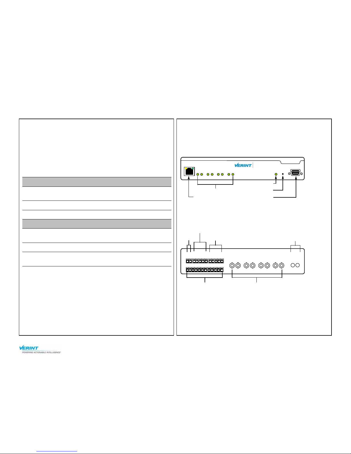
Front
The number of video status LEDs varies depending on the model in the
series: four for the S1704e, eight for the S1708e, and so on:
Back
All edge devices in the series have a model with one pair of optional audio
connectors:
Item Description
Transmitter S1704e, S1704e-AS, S1708e, S1708e-AS,
S1712e, or S1724e
Rack mount bracket One set of bracket
Printed material This installation guide
Options
PDP10-2 distribution
panel
A 19-inch power distribution panel rack mount
supporting up to 10 devices
PS1260 power supply A 12V DC power supply for a single device
PS1281 power supply A high-capacity 12V DC power supply to be used
with the PDP10-2 distribution panel
RS232
ResetStatus
LAN 10/100
Video Status
18765432
S1708e
Nextiva
TM
RJ-45 Ethernet
System status
Reset
RS-232
Video status
IN
AUDIO
OUT
IN8
IN1 IN2 IN3 IN4 IN5 IN6
IN7
VIDEO IN
1
2
12
7
36548
11
10
9
+12V
GND
RX-
RLY1
GND
RLY1
RLY2
RLY2
GND
RX+
TX-
TX+
12V DC
Dry contact input
RS-422/485
Video input
Relay output
Audio (optional)
Nextiva Multiport S17XXe Series Installation Guide
www.verint.com/manuals 2
© 2008-2009 Verint Systems Inc. All Rights Reserved Worldwide.
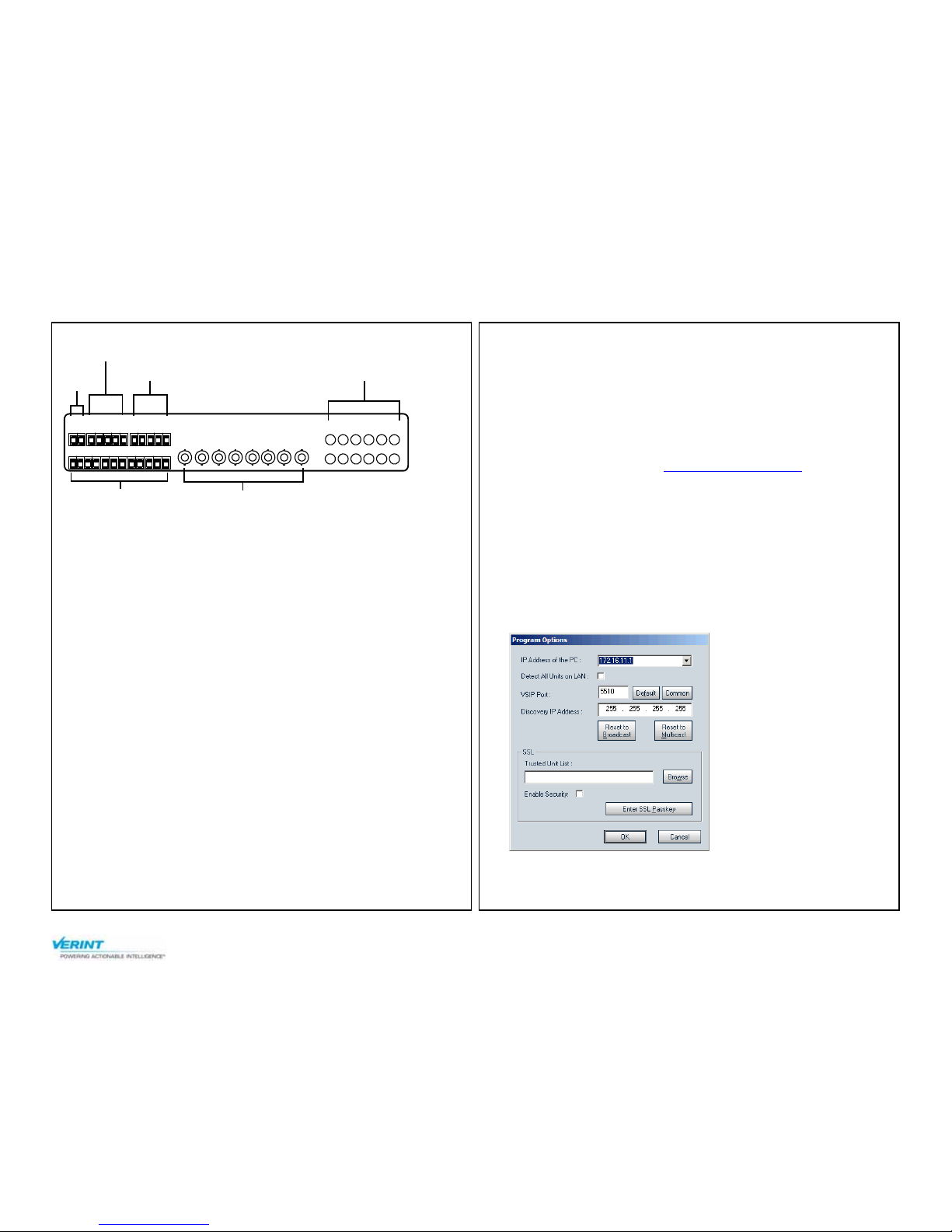
The S1708e and S1712e can also come with 12 audio inputs:
Installation
1. Plug the video cables of the cameras to the BNC connectors on the
device.
2. Establish the Ethernet connection by plugging a cable (straightthrough or crossover) into the network (RJ-45) connector on the front
of the device.
3. Power the device:
If you are using the Nextiva PS1260 power supply:
a. Plug the dashed power supply wire in the Gnd pole on the back of
the device.
b. Plug the other power wire in the +12V pole on the back of the
device.
c. Connect the electric plug into the outlet.
If you are using the Nextiva PS1281 power supply with a PDP10-2
power distribution panel:
For the procedure, refer to the Verint PDP10-2 Installation Guide
document that was shipped with the PDP10-2; you can also find
this document on the extranet (Tech Support > Specifications >
User Manuals).
Ensure that the right voltage is selected (check the 115V/230V red
switch on the back of the power supply).
For any other power supply, refer to the manufacturer documentation
for the proper wiring scheme.
4. If required, connect the serial port of the transmitter to the cameras.
Configuration
To configure the device, you need the SConfigurator software. It is
included on the Verint web site: www.verint.com/manuals
. Copy its
executable file (SConfigurator.exe) to the hard disk of your computer.
To make the transmitter operational in your environment, you need to
connect it to the IP network. Then you complete the configuration with
SConfigurator or your video management software.
1. Ensure that the device is powered and connected to the Ethernet
network.
2. Start SConfigurator by double-clicking SConfigurator.exe on your
hard disk.
3. In the General tab, click Program Options.
4. Check Detect All Units on LAN.
5. Ensure that the VSIP Port is 5510; otherwise, click Default.
VIDEO IN
IN8IN7IN6IN5IN4IN3IN2IN1
1
2
12
7
36548
11
10
9
+12V
GND
RX-
RLY1
GND
RLY1
RLY2
RLY2
GND
RX+
TX-
TX+
AUDIO IN
195
8624
371211
10
12V
DC
Dry contact input
RS-422/485 Audio input
Relay output
Video input
 Loading...