

Verint S1100 User Manual
S1100 User Manual


S1100
Firmware Release 3.30
User Manual
Verint Video Solutions

© 2004 Verint Systems Inc. All rights reserved.
By providing this document, Verint Systems Inc. is not
making any representations regarding the correctness or
completeness of its contents and reserves the right to alter
this document at any time without notice.
Verint, Actionable Intelligence, BehaviorTrack, Dellis,
HealthCheck, Lanex, Loronix, Loronix Video Manager,
MotionTrack, microDVR, nDVR, netDVR, Powering Actionable
Intelligence, SmartSight, and Video Manager are trademarks
of Verint Systems Inc., its subsidiaries or affiliates. All other
registered trademarks, trademarks, and any associated logos
are the properties of their respective owners.
Published by:
Verint Video Solutions
1800 Berlier Street
Laval (Quebec)
Canada
H7L 4S4
www.verint.com/smartsight
Publication date: February 10, 2005
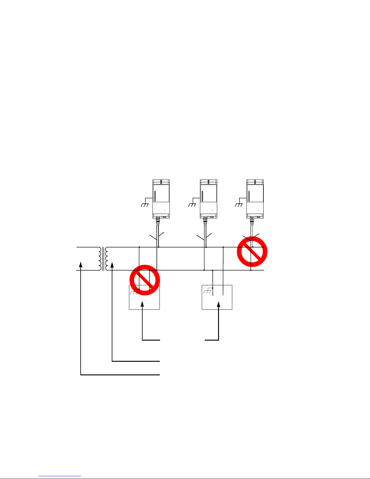
Warning: If you connect multiple S1100 units on the same
24V AC power source, always wire them the same
way: The red power wires (VIN) of all units must be
on the same terminal or lead of the AC power source.
This is because the black power wire (VIN_RETURN)
of the S1100 is internally connected to the S1100
chassis (earth). Swapping the power connection
scheme from unit to unit will short out the AC power
source.
Warning: If you connect third-party equipment with an
earth-referenced power input, it is important to plug
the earth-referenced terminal of that device to the
same AC power source terminal as the S1100 black
wire. Failing to do so will short out the AC power
source.
Black
Stat
us
T
M
Red
Black
Stat
us
T
M
Red
Third-party
equipment
Isolated 24V AC
AC main
Red
T
M
Stat
us
Black
Verint Video Solutions iii

iv Verint Video Solutions

Contents
Preface ........................................................................ ix
Who Should Read this Manual ......................................x
How to Use this Manual ...............................................x
Contents ..............................................................x
Conventions ........................................................xi
Related Documentation ........................................ xii
Related Verint Video Solutions Products ................. xii
About Us ................................................................. xii
Warranty ................................................................ xiv
Chapter 1
About the S1100 ....................................................... 2
Shipment ................................................................. 3
Casing Description ..................................................... 4
Chapter 2
Frequency Bands and Channels ................................... 6
Wireless Cells ........................................................... 7
TPC ......................................................................... 9
DFS ......................................................................... 9
Colocated Systems ...................................................11
RF Planning .............................................................17
Overview ................................................... 1
Security .............................................................. 2
Video ................................................................. 2
System and RF Planning ............................ 5
2.4 GHz Band ...................................................... 6
5 GHz Band ......................................................... 6
Distance Limitations ............................................12
2.4 GHz Band .....................................................12
5 GHz Band in North America ...............................14
5 GHz Band in Europe ..........................................15
Location Evaluation .............................................18
Antenna Requirements ........................................20
Interference .......................................................21
RF Exposure Considerations .................................21
Chapter 3
Cable for Power, Video, and Serial Data .......................24
Computer Requirements ............................................25
Configuring a Point-to-Point System ............................25
Verint Video Solutions v
Configuring and Installing the Unit .......... 23

Contents
Configuring a Point-to-Point Repeater ..........................27
Installing the Equipment ...........................................28
Installing the S1100 Units ....................................29
Performing the RS-422/485 Serial Connection ........31
Adding an Antenna ..............................................33
Configuring the I/Os .................................................34
Audio ................................................................34
Alarms ..............................................................36
Performing a Hardware Reset .....................................37
Status LED ..............................................................37
Chapter 4
Using the Configuration Assistant ............ 39
Getting Started ........................................................40
Performing a Basic Configuration ................................42
Performing an Advanced Configuration ........................43
General .............................................................44
Wireless ............................................................44
Video ................................................................46
Audio ................................................................47
Serial Port ..........................................................47
Checking the Connection Statuses ..............................48
Wireless ............................................................48
Video ................................................................49
Audio ................................................................49
Serial Port ..........................................................50
Repeater Consideration .............................................50
Accessing the CLI of the Unit .....................................54
Chapter 5
Understanding the On-Screen Display ...... 57
Quadrant 2: SmartSight Logo ....................................58
Quadrant 3: Receiver Settings ...................................59
Quadrant 4: Transmitter Settings ...............................59
Chapter 6
Updating the Firmware ............................ 61
Appendix A Factory Default Configuration ................ 65
Appendix B
Cable Descriptions.................................. 67
CAB9P ....................................................................68
CAB8P ....................................................................70
Appendix C
Appendix D
Appendix E
DTE and DCE Connections ....................... 71
Surge Protection .................................... 75
RF Contact between Masters .................. 77
Appendix F Separation Between Units Using Adjacent
vi Verint Video Solutions
Channels ................................................ 81

S1100 User Manual
Appendix G Technical Specifications ......................... 87
Glossary ..................................................................... 91
Index .......................................................................... 97
Compliance ............................................................... 103
Verint Video Solutions vii

viii Verint Video Solutions

Preface
The S1100 User Manual presents the information and
procedures for installing, configuring, and using the
SmartSight® S1100 wireless video systems.
Verint Video Solutions ix

Preface
Who Should Read this
Manual
This manual is intended for managers, engineers, and
technicians who will use the S1100 units. It provides conceptual
information on how to configure, install, and operate the units.
This manual assumes that you are familiar with:
Installation and manipulation of electronic equipment
General use of computers
Microsoft Windows operating systems
Pan-tilt-zoom (PTZ) platforms (cameras and keyboards)
Radio frequency (RF) regulations
How to Use this Manual
The S1100 User Manual contains all the information needed to
install, configure, and use an S1100 unit.
Contents
This manual is divided into the following chapters:
1. Overview—Provides a brief description of the features of
the S1100 unit and an illustration of its casing.
2. System and RF Planning—Lists the available frequency
bands and describes planning operations relative to system
setup and radio frequency (RF).
3. Configuring and Installing the Unit—Presents the
configuration and installation procedures for the S1100
unit.
4. Using the Configuration Assistant—Explains how to
program the S1100 unit using the SmartSight Configuration
Assistant.
5. Understanding the On-Screen Display—Presents the
four quadrants on the video monitor connected to the
S1100 receiver unit.
x Verint Video Solutions

S1100 User Manual
6. Updating the Firmware—Describes how to upgrade the
firmware of the S1100 unit.
The manual also includes the following appendixes:
A. Factory Default Configuration—Lists the default
parameter values of the S1100 unit.
B. Cable Descriptions—Describes the 8-pin and 9-pin
cables supplied with the unit.
C. DTE and DCE Connections—Presents diagrams
explaining how to differentiate and connect data
terminal equipment (DTE) and data communication
equipment (DCE).
D. Surge Protection—Describes how to protect the S1100
unit from voltage and current surges.
E. RF Contact between Masters—Explains how to ensure
that two master units “see” each other.
F. Separation Between Units Using Adjacent
Channels—Lists the minimum distances between units
using adjacent frequency channels.
G. Technical Specifications—Lists the complete technical
specifications of the S1100 units.
A glossary, an index, and compliance information complete the
manual.
Conventions
The following typographic conventions are used throughout this
manual:
Visual cue Meaning
Connect The name of an interface element you have to act
on. A key to press. The value of an interface
element.
Advanced > VSIP Any sequence of steps (in the menu structure of
a graphical application, in the navigation
structure of a web site, and so on).
connection_name Text that must be replaced by a user-supplied
value. Text representing variable content.
S1100.xh
The name of a command, file, or directory. Text
that appears on the screen. Examples of
user-supplied values.
Verint Video Solutions xi

Preface
Related Documentation
In addition to this manual, the following documentation is also
available:
S1100 Installation Guide—Contains the configuration
steps and the installation procedure for the S1100 unit.
SConfigurator User Manual—Presents the instructions on
how to use a proprietary Verint Video Solutions software to
perform advanced configuration tasks.
Release Notes—Contain information about S1100 upgrades
and known issues still under investigation, as well as a
description of features not covered in this version of the
documentation.
All these documents are contained on the SmartSight Utilities
CD shipped with the unit. Furthermore, a paper copy of the
installation guide is included with your order.
Related Verint Video Solutions
Products
You can use the S1100 units with the S3100 outdoor wireless
bridge. For more details about this product, visit our web site.
For pricing information, call your dealer.
About Us
Verint Systems (NASDAQ: VRNT) is a leading global provider of
video security, surveillance and business intelligence solutions.
Verint Video Solutions transform digital video into actionable
intelligence: timely, mission-critical insights for faster, more
effective decisions.
Today, more than 1000 companies in 50 countries use Verint
Systems solutions to enhance security, boost operational
efficiency, and fuel profitability.
xii Verint Video Solutions

S1100 User Manual
Web Site
For information about the SmartSight line of products, visit
www.verint.com/smartsight. To download the product
specifications, application notes, and user documentation, as
well as to request the latest versions of firmware and software,
use the following links:
To access Visit
Complete selection of what is
available:
User documentation: www.verint.com/smartsight/manuals
Various tools and demos: www.verint.com/smartsight/tools
Firmware upgrade requests: www.verint.com/smartsight/firmware_
www.verint.com/smartsight/support
upgrade
Support
If you encounter any type of problem after reading this manual,
contact your local distributor or Verint Video Solutions
representative. You can also use the following sections on our
web site to find the answers to your questions:
To access Visit
Technical support request form: www.verint.com/smartsight/request
Solution database (FAQ): www.verint.com/smartsight/faq
Login to our customer service
system:
www.verint.com/smartsight/account
Verint Video Solutions technical support personnel is available
to help you use your SmartSight units and the related software:
On the web: www.verint.com/smartsight/request
By phone: 1 888 494-7337 (North America) or
+1 450 686-9000 Monday to Friday, from 8:30 to
17:30 EST
By fax: +1 450 686-0198
Verint Video Solutions xiii

Preface
Warranty
Each product manufactured by Verint Systems is warranted to
meet all published specifications and to be free from defects in
material and workmanship for a period of two (2) years from
date of delivery as evidenced by the Verint Systems packing
slip or other transportation receipt. Products showing damage
by misuse or abnormal conditions of operation, or which have
been modified by Buyer or repaired or altered outside Verint
Systems factory without a specific authorization from Verint
Systems shall be excluded from this warranty. Verint Systems
shall in no event be responsible for incidental or consequential
damages including without limitation, personal injury or
property damage.
The warranty becomes void if the product is altered in any way.
Verint Systems responsibility under this warranty shall be to
repair or replace, at its option, defective work or returned parts
with transportation charges to Verint Systems factory paid by
Buyer and return paid by Verint Systems. If Verint Systems
determines that the Product is not defective within the terms of
the warranty, Buyer shall pay all handling and transportation
costs. Verint Systems may, at its option, elect to correct any
warranty defects by sending its supervisory or technical
representative, at its expense, to customer’s plant or location.
Since Verint Systems has no control over conditions of use, no
warranty is made or implied as to suitability for customer’s
intended use. There are no warranties, expressed or implied,
except as stated herein. This limitation on warranties shall not
be modified by verbal representations.
Equipment shipped ex works Verint Systems factory shall
become the property of Buyer, upon transfer to the common
carrier. Buyer shall communicate directly with the carrier by
immediately requesting carrier’s inspection upon evidence of
damage in shipment.
Buyer must obtain a return materials authorization (RMA)
number and shipping instructions from Verint Systems prior to
returning any product under warranty. Do not return any Verint
Systems product to the factory until RMA and shipping
instructions are received.
xiv Verint Video Solutions

Overview
The S1100 is a professional video transmission product
designed for the CCTV (closed circuit television) market. It
allows digital video transmission over multiple license-free
bands. It delivers high-quality MPEG-4-based video at
30 frames per second in NTSC (25 in PAL). This wireless system
is built on open standards to provide long-term investment
protection.
Note: The S1100 units require professional installation.
Verint Video Solutions 1

1: Overview
About the S1100
Each S1100 system consists of a video transmitter (-T) and a
video receiver (-R) unit. Unless otherwise specified, the word
S1100 refers to any of these units.
Each unit is configured to operate, right out of the box, with the
most popular camera data port configuration (4800 baud,
8 data bits, no parity, 1 stop bit).
The S1100 covers the 2.4 GHz and 5 GHz frequency bands in
North America and Europe.
You can buy 12V DC and 24V AC units. A unit pair does not
need to have the same input voltage.
Security
Every S1100 unit includes the SDCF (SmartSight distributed
coordinated function) security feature. This proprietary MAC
(media access control) protocol uses AES encryption with key
rotation over the wireless link to secure the audio and video
communication between the units.
Video
The S1100-R unit has one video output. The S1100-T has one
video input with two encoders; by default, only one encoder is
available.
The video frame rate of the units can be:
NTSC—1 to 7, 10, 15, or 30 frames per second (fps)
PAL—1 to 6, 8, 12, or 25 fps
2 Verint Video Solutions

S1100 User Manual
The S1100 units can have the following video resolutions and
maximum frame rates (in frames per second):
Resolution Number of
columns
NTSC/PAL NTSC PAL NTSC PAL
QCIF 176 128 144 30 25
CIF 352 240 288 30 25
2CIF 352 384 448 30 25
2CIFH 704 240 288 30 25
4CIF 704 480 576 15 12
All lines 352 480 576 30 25
2/3 D1 480 480 576 15/30 * 12/25 *
VGA 640 480 576 15/30 * 12/25 *
Number of lines Maximum frame
rate
* Without noise, I/Os, and other factors affecting quality, the
unit can achieve the highest frame rate.
Shipment
Your S1100 shipment contains the following items:
The requested transmitter and receiver, each coming with
an integrated patch antenna (with a gain of 8.5 dBi in the
2.4 GHz band or 13 dBi in the 5 GHz band)
Two wall mount bracket sets, already installed on the units
Two pole mount bracket sets
Two cable assemblies for video, power, and serial port
(CAB9P)
The SmartSight Utilities CD containing the documentation
and release notes for the unit
The S1100 Installation Guide
This user manual
Verint Video Solutions 3
1: Overview
The shipment may also contain the following options:
One or two high-gain antennas
Warning: When choosing antennas, you must ensure that
the combined transmission power of the unit and
antenna does not exceed the maximum power
established by your country’s regulations. For
more information, see page 20.
One or two junction boxes (JBOX)
One or two alarm/audio cable assemblies (CAB8P)
One or two power supplies
Note: If you are using power supplies other than those
supplied by Verint Video Solutions, you need to
ensure that they have a minimum capacity of 1A
(12V DC) or 30 VA (24V AC).
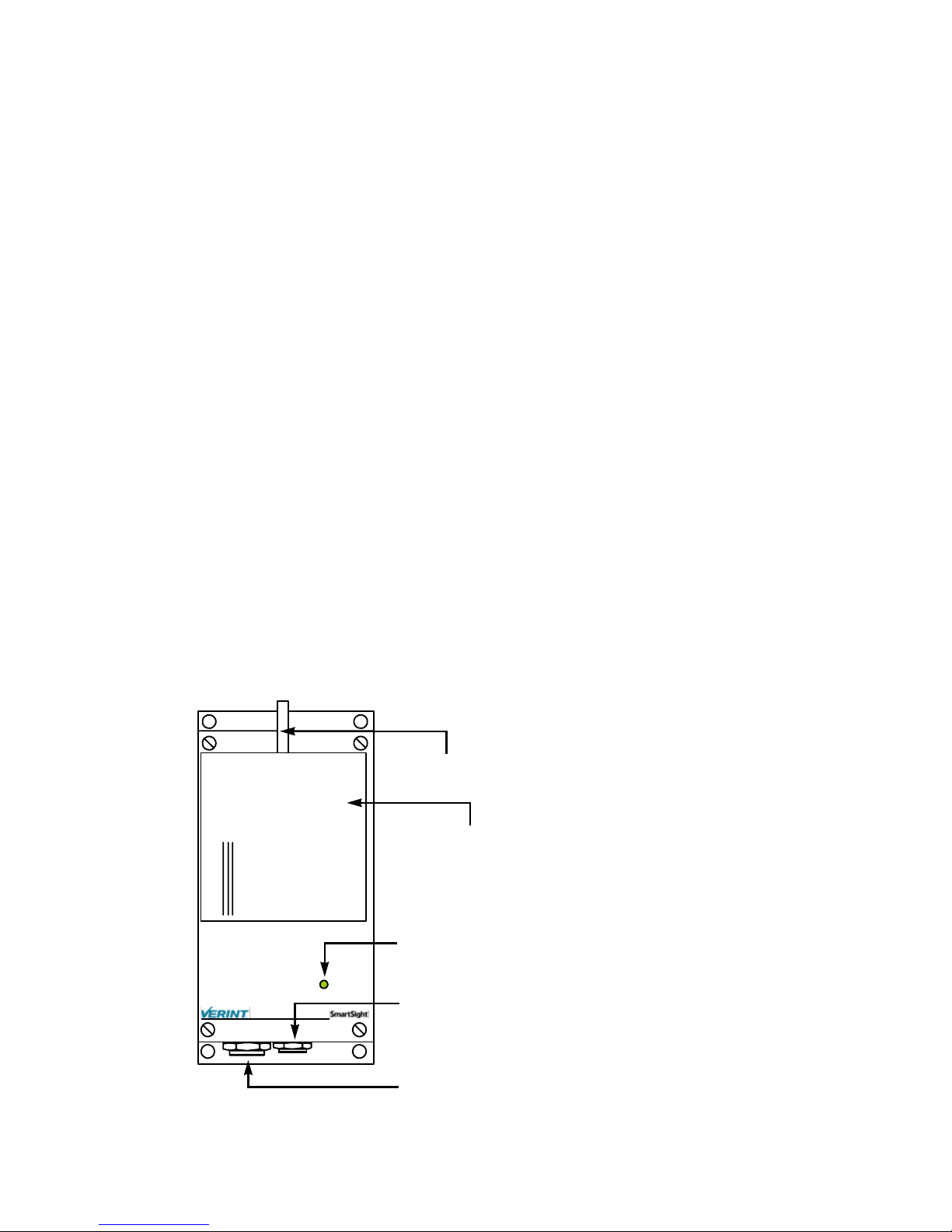
Casing Description
The S1100 electronics are enclosed in a weather-tight cast
aluminum module. All cable entries are mounted on the
underside of the module to maintain its weatherproof
properties. The front panel integrates one bicolor visual
indicator that illustrates the unit’s operational state.
Antenna port
Integrated antenna
Status indicator
Status
Auxiliary connector (alarm, audio)
4 Verint Video Solutions
Main connector (video, power, serial
port)

System and RF
Planning
For best operation, you must carefully plan the setup and
location of your radio systems and antennas. Planning is
especially required if you want to install many systems in the
same area, in order to prevent radio interference between the
colocated units. In all cases, follow the recognized RF
installation practices.
One radio system is a receiver and a transmitter using the
same wireless passkey.
Verint Video Solutions 5

2: System and RF Planning
Frequency Bands and
Channels
The S1100 supports communications in the following frequency
bands, in North America and Europe:
2.4 GHz OFDM, also known as 802.11g
5 GHz OFDM, also known as 802.11a
2.4 GHz Band
The 2.4 GHz band provides 11 channels in North America and
13 in Europe. In these two regions, only channels 1, 6, and 11
are non-overlapping. All these channels are for indoor or
outdoor use. The center frequencies of the channels are:
Channel Frequency (GHz) Channel Frequency (GHz)
1 2.412 8 2.447
2 2.417 9 2.452
3 2.422 10 2.457
4 2.427 11 2.462
5 2.432 12 2.467 (Europe only)
6 2.437 13 2.472 (Europe only)
7 2.442
5 GHz Band
In the 5 GHz band, the number of available channels and
sub-bands vary depending on the country of operation.
Most European countries adhere to the DFS (dynamic frequency
selection) and TPC (transmit power control) regulations
established by the European Telecommunications Standards
Institute (ETSI); these regulations apply to the 5 GHz
frequency band only. To know which bands are available in your
country of operation and whether your country adheres to DFS
and TPC, refer to the Wireless Frequency Plan document
located on our web site (Tools & Demos section).
6 Verint Video Solutions

S1100 User Manual
In North America, nine channels are available in the 5 GHz
band, all non-overlapping and for indoor or outdoor use. The
center frequencies of these channels are:
Channel Frequency (GHz) Channel Frequency (GHz)
52 5.26 149 5.745
56 5.28 153 5.765
60 5.30 157 5.785
64 5.32 161 5.805
165 5.825
In Europe, the 11 non-overlapping channels, for indoor or
outdoor use, are:
Channel Frequency (GHz) Channel Frequency (GHz)
100 5.50 124 5.62
104 5.52 128 5.64
108 5.54 132 5.66
112 5.56 136 5.68
116 5.58 140 5.70
120 5.60
Wireless Cells
A wireless network is designed such that information can travel
back and forth between two points without the need for wires.
Wireless devices are grouped into wireless cells. The devices in
a cell communicate together on the same frequency channel
and share the same wireless passkey.
Verint Video Solutions 7
2: System and RF Planning
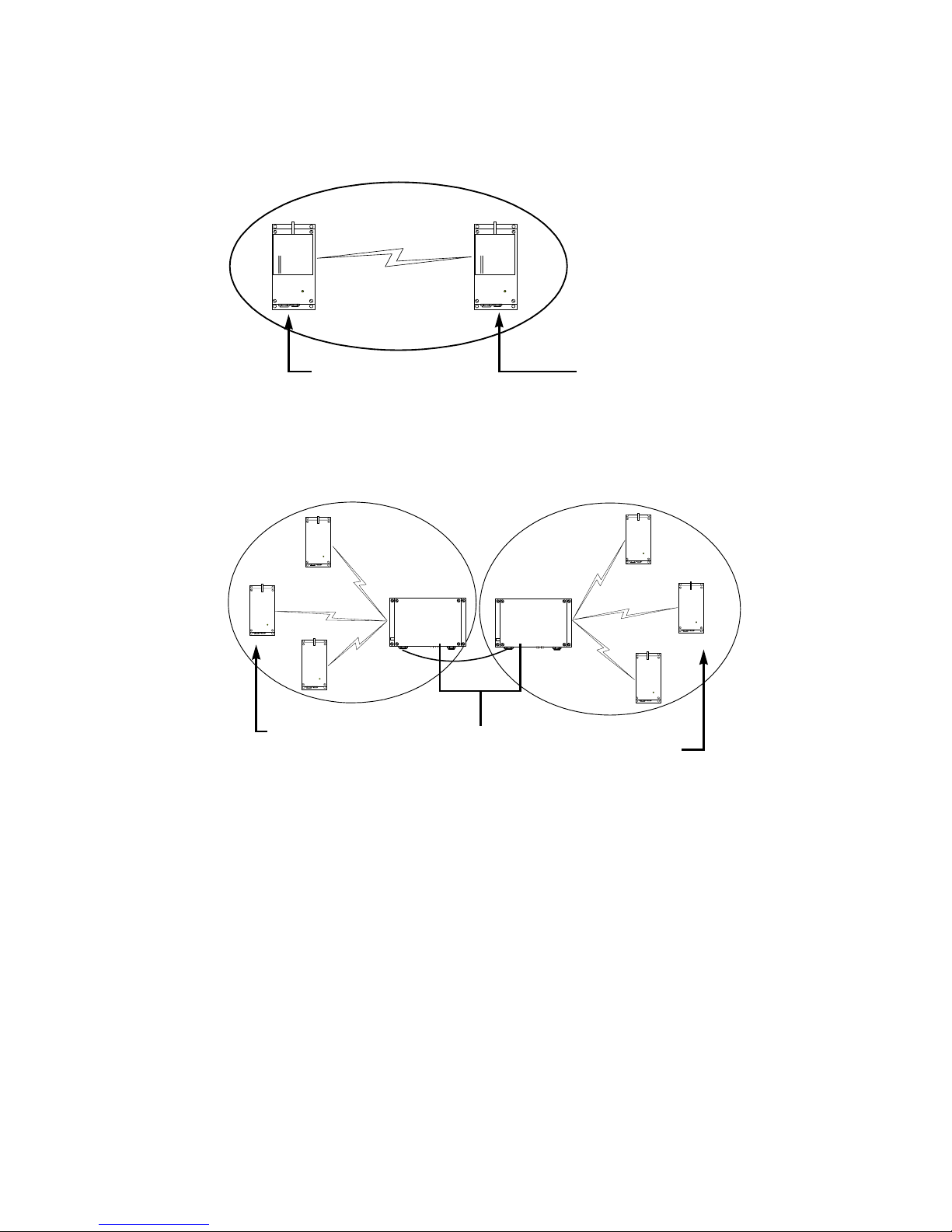
You can use the S1100 units in two types of applications:
Point-to-point system, which requires a single wireless cell:
-T -R
Client Master
The S1100 receiver is the SDCF master, and the transmitter
is the client.
Point-to-point repeater, which is the combination of two
wireless cells:
1
2
3
transmitters
S3100
S3100
RepeaterCell1, for the
Cell2, for the
receivers
1
2
3
When planning your wireless systems, you have to take into
account the firmware versions of the involved units:
The two S1100 units making up a pair must have the same
firmware version.
8 Verint Video Solutions

S1100 User Manual
In a point-to-point repeater, it is recommended that the
S1100 units have the same firmware versions as their
associated S3100 master. Use the following matrix to
ensure complete compatibility between your units:
S1100
V3.20 V3.30
V2.55 no no
V2.56 no no
Master S3100
As far as updating the firmware, you should:
1. Update the firmware of all S1100 pairs, starting with the
remote unit.
2. Change the IP address of the computer running
SConfigurator (refer to the S3100 User Manual).
V2.60 yes yes
V3.20 yes yes
V3.30 yes yes
3. Update the firmware of the two S3100 units.
TPC
If the country of operation of the S1100 unit requires
conformity to the TPC (transmit power control) regulations, the
transmission power of its radio is automatically reduced by 3 dB
before leaving the Verint Video Solutions factory. However, in
case of a weak wireless link (that is, a link with an RF margin of
less than 15 dB), you have the opportunity to use the
maximum transmission power (see page 46).
DFS
To follow the DFS (dynamic frequency selection) regulations
specified by ETSI for the selected country, it is the master unit
that performs the tasks relative to frequency channel selection
and radar detection. In other words, you cannot choose the
frequency channel on which the unit will run.
Verint Video Solutions 9
2: System and RF Planning
The automatic selection of the frequency channel limits the
number and the configuration of the wireless cells.
Furthermore, when colocating many cells, all masters must
“see” each other.
Note: DFS is required only in the 5 GHz band.
You should start the master first, then power the client when
the other unit is in normal operation.
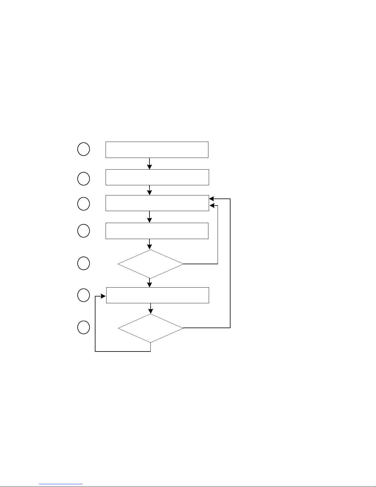
A master unit in DFS mode goes through the following
sequence when booting up:
1
2
3
4
5
6
7
Unit initialization (3 seconds)
Starting order delay (0-15 minutes)
Frequency scan (10-20 seconds)
Radar detection (60 seconds)
yes
Radar detected?
no
Normal operation
yes
Radar detected?
1. The unit goes through the standard startup procedure.
2. The starting order delay ensures that colocated masters will
not select a frequency channel at the same time, therefore
minimizing the possibility that they choose the same one.
For more information about the starting order, see page 45.
10 Verint Video Solutions
no
S1100 User Manual
3. The unit scans the available frequencies (based on the
selected country) and automatically selects a channel. In
the selection process, channels already used by colocated
masters will be discarded at first.
4. The unit listens for 60 seconds on the selected channel to
detect possible radar interference.
5. If a radar is detected on the channel, the unit returns to the
scan process. Otherwise, it continues its bootup procedure.
6. The unit runs normally.
7. If a radar is detected, the unit immediately goes back to
the scan process to select another channel.
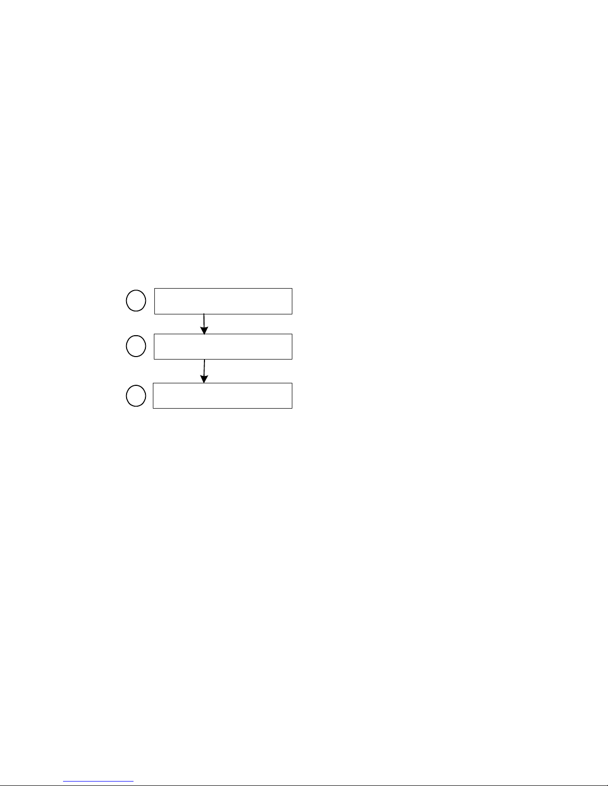
The boot sequence of client (transmitter) units is:
Unit initialization (3 seconds)
1
Roaming (2-25 seconds)
2
Normal operation
3
1. The unit goes through the standard startup procedure.
2. The unit roams through the channels in the available
frequency bands to locate its master.
3. When the master is located, the client unit runs normally on
the selected frequency channel.
Colocated Systems
When installing colocated systems, you have to carefully plan
the position of the units in order to prevent radio interference.
You can operate many wireless cells in the same location,
provided you follow guidelines relative to frequency band and
channel, distance, wireless passkey, and location.
Regarding frequency channel, you cannot manually select one
in the 5.40–5.725 GHz band in Europe; for the detailed
procedure, see page 15.
Verint Video Solutions 11

2: System and RF Planning
The wireless passkeys of colocated cells must be different from
one another, regardless of their frequency channels.
Distance Limitations
The distance limitations between units are:
To avoid material damages, you must never power any two
units while their antennas are facing one another with a
distance of less than 10 feet (3 meters).
If using adjacent channels, see page 81 for the
recommendations on the minimum distances to respect.
With different frequency bands or with non-adjacent
channels in the same band, two units can be side by side
with no minimum distance between them.
2.4 GHz Band
In the 2.4 GHz band in North America and Europe, you can use
the three non-overlapping channels (channels 1, 6, and 11) to
colocate wireless cells.
Up to Three Point-to-Point Systems
As long as you follow the recognized RF installation practices,
you can colocate three S1100 point-to-point systems without
special consideration for antenna placement and type. You
simply have to:
1. Assign a unique wireless passkey to each system.
2. Assign channel 1 to one system, channel 6 to the second
system, and channel 11 to the last system. For example:
Unit Channel Wireless passkey
S1100-T 1 1 1dfi340mndpha23v
S1100-R 1 1 1dfi340mndpha23v
S1100-T 2 6 pvaeodmq820pasqs
S1100-R 2 6 pvaeodmq820pasqs
S1100-T 3 11 moxsa41o0s3n7azx
S1100-R 3 11 moxsa41o0s3n7azx
12 Verint Video Solutions

S1100 User Manual
Up to Six Point-to-Point Systems (< 180°
Coverage)
You can install up to six S1100 receivers on the same side of a
building or on the same mast, with their antennas pointing
within the same direction (within a 180° angle of each other).
You have to:
1. Assign a unique wireless passkey for each system.
2. Assign the same channel to two adjacent pairs of units.
Assign the channels in the following order: 1, 11, 6.
For example:
Unit Channel Wireless passkey
S1100-T 1 1 1570fullummtlh2k
S1100-R 1 1 1570fullummtlh2k
S1100-T 2 1 270citehullj8y2h
S1100-R 2 1 270citehullj8y2h
S1100-T 3 11 yyyypu76leplep11
S1100-R 3 11 yyyypu76leplep11
S1100-T 4 11 jyjyjypkpkpkbxbx
S1100-R 4 11 jyjyjypkpkpkbxbx
S1100-T 5 6 zxcvbnmlkjhgfdsa
S1100-R 5 6 zxcvbnmlkjhgfdsa
S1100-T 6 6 qwertyuioplkjhgf
S1100-R 6 6 qwertyuioplkjhgf
3. Set the RF bit rate of each system sharing a channel to a
high enough value to accommodate the cumulative video
throughput configured in both systems.
This higher value is required because the systems sharing
the same channel will also share the available radio channel
bandwidth.
Verint Video Solutions 13
2: System and RF Planning
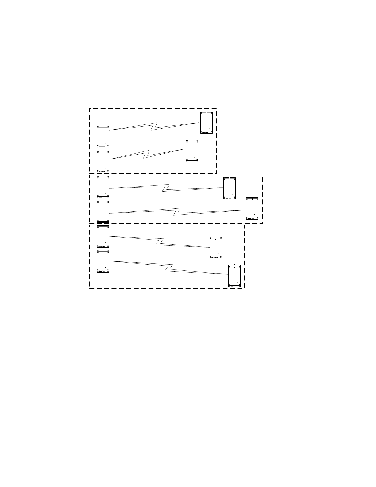
4. Install the individual receivers that share a channel as close
as possible to each other; do the same for the two
corresponding transmitters. All units sharing a channel
must have a clear RF line of sight to each other (that is, no
“hidden node”); they must also “hear” each other. For
instance, transmitter 1 must be able to hear both receivers
and transmitter 2.
1
1
1
1
2
2
11
3
4
11
5
6
3
4
5
6
6
6
If the distance between the transmitters sharing a channel is
greater than 300 feet (91.5 meters), call the Verint Video
Solutions systems engineering group for help.
5 GHz Band in North America
All channels in the 5 GHz band are non-interfering.
Up to Nine Point-to-Point Systems
As long as you follow the recognized RF installation practices,
you can install up to nine S1100 point-to-point systems in
colocation mode, on the same pole or on different sides of a
building, without sharing channels.
14 Verint Video Solutions
 Loading...