

Mounting and Operating Instructions of
RP105 Camera
for mobile video surveillance
01 2006

Foreword
Dear customer,
By selecting a product from Verint Video Solutions GmbH you have purchased a professional device that
ensures highest quality and reliability. Thank you for your confidence in our product. We would like to ask you
to read through the following information carefully before you begin operating the device. This way you can
completely enjoy all the benefits this product provides.
In presenting this document, Verint Systems does not make any guarantee regarding the correctness or
completeness of its contents, and reserves the right to alter this document at any time without notice.
This document may not be duplicated, photocopied, reproduced, translated, transferred to an electronic
medium or converted into machine-readable form without the previous written approval of Verint Video
Solutions GmbH.
© 2006 Verint Systems Inc.
2

Contents
General Information
Product Overview........................................................................................................................................................ 4
Safety Information....................................................................................................................................................... 4
Place of Installation .................................................................................................................................................... 5
Scope of Delivery......................................................................................................................................................... 5
Accessories / Additional Equipment..................................................................................................................... 5
Warranty ......................................................................................................................................................................... 5
Installation
System Overview......................................................................................................................................................... 6
Detailed View ............................................................................................................................................................... 6
Installation..................................................................................................................................................................... 7
Connecting Diagram................................................................................................................................................... 8
Initial Operation........................................................................................................................................................... 8
Appendix
Technical Data.............................................................................................................................................................. 9
Cleaning and Maintenance / Servicing Information ......................................................................................10
Troubleshooting......................................................................................................................................................... 10
Technical Support......................................................................................................................................................11
Version Date
Ver 1.0 18.01.2006
3

General information
Product overview
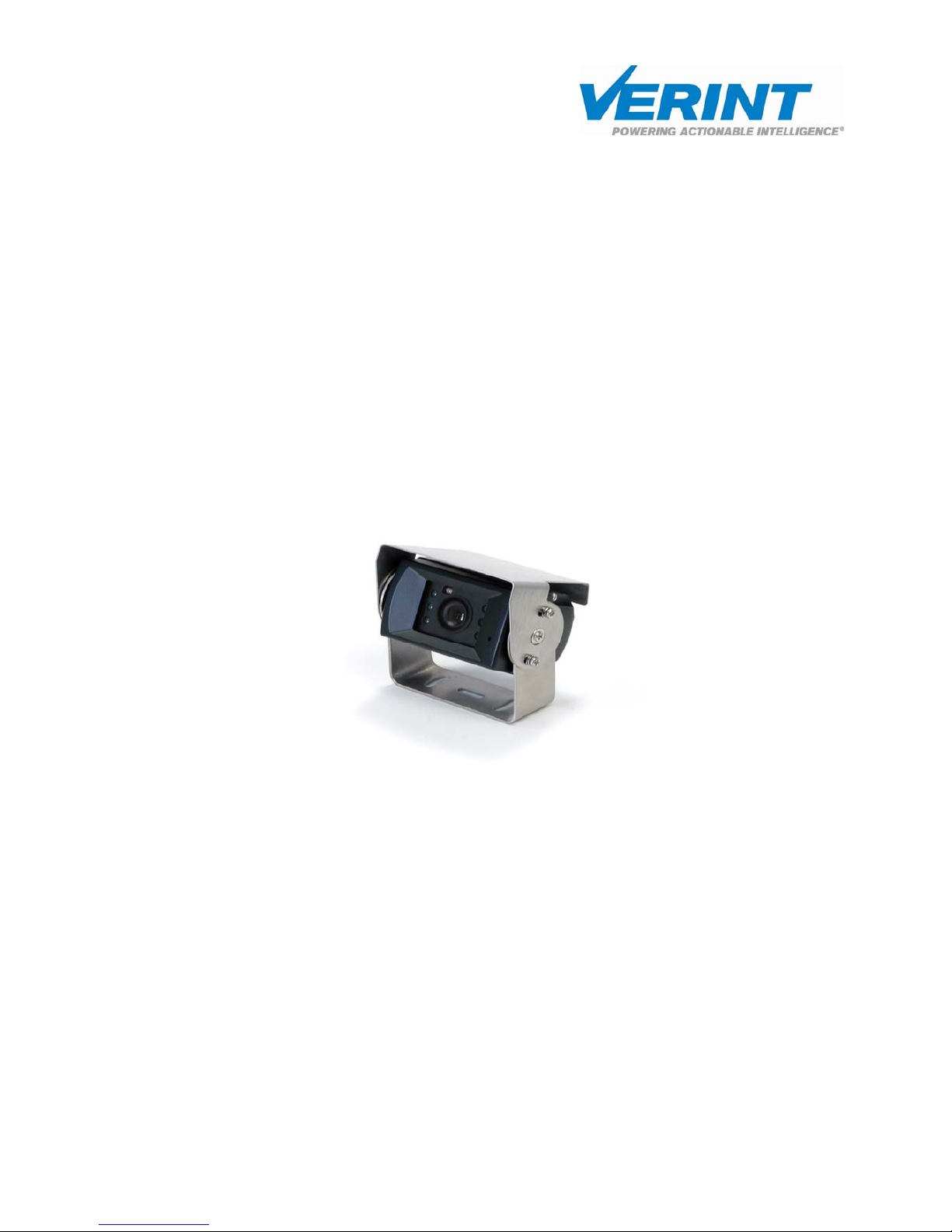
The weatherproof Verint RP105 Back Eye Camera offers a reliable mobile solution in buses and trucks as
rearview camera system. The camera comes equipped with a wide-angle lens and makes backing up safer. The
driver can immediately see obstacles that suddenly appear and can react to them more quickly.
The camera can be operated in very bright (outdoor areas) but also in dark areas (outdoor darkness or indoor
areas). Integrated infrared LED lighting ensures that the device can be operated in complete darkness and it is
automatically switched on at dusk.
When combined with our wide range of recorders and monitors, the RP 105 camera provides a comprehensive
networked digital video surveillance solution to help public transport providers protect people and property,
refute false claims, and reduce frivolous lawsuits.
Safety Information
• Read these instructions carefully before operating the device. This will help prevent possible damages
from improper use.
• The device should only be installed by qualified professionals according to existing VDE (Association
for Electrical, Electronic & Information Technologies) regulations.
• Operate the cameras exclusively using the normal service voltage indicated.
• Observe any warnings on the device.
• The camera should only be used in a dry, dust-free and non-hazardous environment.
• Never use the device for purposes others than those for which it was intended.
• The device should be repaired only by qualified professionals.
• Should liquids or hard objects enter the housing, disconnect the power supply immediately. Have the
device checked by a qualified professional before you use it again (risk of electric shock).
• Operate the device only indoors.
• To avoid internal heat build-up in the device:
- the device should not be subjected to direct sunlight
- should have adequate distance from direct heat sources
For cleaning and maintaining the camera, follow the directions given in these instructions. General
information
4

General Information
Place of Installation
The camera is specially designed for video surveillance in buses and fullfils the required European standards
for public transport.
Scope of Delivery
• High-resolution vehicle back eye camera with 3.0 mm fixed lens
• Connection cable
• Mounting materials
• Mounting instructions
Accessories / Additional Equipment
• Video cable 75 Ohm (e.g. RG-59)
• BNC connector
Warranty
The warranty is valid for 24 months and begins on the date of delivery. Any defects must be reported within
10 working days following delivery of the product. Hidden defects must be reported immediately when they
are discovered.
The warranty does not include damages to the products caused by accidents, unsuitable or improper usage,
non-authorized or incorrect mounting or startup, incorrect or improper handling, damages during transport or
improper maintenance. The warranty does not include costs you incur from installation or initial operation as
part of a warranty claim.
In response to a warranty claim we can choose to provide a replacement or repairs within an appropriate
period of time. If the defect is not successfully remedied we have the option of rescission or reduction, in case
of a negligible defect of reduction only.
5

Installation
System Overview
T
he Back Eye Camera RP 105 requires a stabilized 12 V DC power supply and
has a max. power input of approx. 2.5 W.
12 V DC (connection at recorder)
Video signal (connection at recorder)
Cable connections
It is possible to lay separate cables for all connections.
Video = coaxial cable 75 Ω, (F)BAS, 1 Vss/75 Ω
Power supply = operating voltage 12 V DC / GND
Detailed View
All specifications in mm!
Installation
Installation
6

Installation
Installation
Information on camera mounting location
• Keep an adequate distance to direct heat sources.
• Do not point the camera towards artificial lighting, the sun, the sky or in the direction of a window.
The best image quality will be achieved if both camera and lighting point to the area you want to
record.
• Reduce the picture section to the essential area and install the camera as close to the object as
possible.
• Avoid head lights as back light in the video picture (also caused by reflections, e.g. on window panes).
Mounting the Camera
Attach the camera along with the accompanying mounting materials to the position you have chosen. The
housing of the RP 105 can be used for marking the mounting holes.
mounting screws
clamp
holder
2-sided adhesive tape
clamp
holder
infrared lighting
(IR-Leds)
brightness
mounting
screws
lock washer
sun shield
mounting screws
7

Installation
Installation
Connecting Diagram
Plug assignment:
PIN 1 +12 V DC red
PIN 2 Heat (optional) green
PIN 3 Not assigned -
PIN 4 Video output clear
PIN 5 Audio (optional) blue
PIN 6 Reversed display yellow
PIN 7 Ground shield
• Connect the video output signal of the camera (PIN 4, clear wire) using a suitable video cable
(insulated coaxial cable, 75 Ohm) to the designated video input of the recorder.
• The recorder provides service voltage to the attached cameras (12 V DC). Use a suitable cable for
connecting the power supply (PIN 1, red wire) and make sure the connector fits correctly and cleanly
and has the correct polarity. Operate the camera exclusively using the normal service voltage indicated.
• The standard Back Eye Camera RP105 is designed to show reversed images. The reverse-image display
should be used if the camera is mounted on the vehicle pointing backward. If the reverse-image
display is not used, the PIN 6 (yellow wire) should be connected to ground (PIN 7).
• Lay the cable from the camera to the recorder (or to the monitor). Lay the cable from the camera
directly into the interior of the vehicle. It is important to ensure that the safety of the driver is not
impaired.
Initial operation
Check to see that the camera provides an acceptable video signal and that the picture section was chosen
correctly. Correct the angle if necessary.
Please never open the dome camera itself. There are no further setting options on the inside of the camera
module.
8

Appendix
Technical Data RP 105
CCD Sensor 1/3“ Interline CCD (Sharp)
Max. pixels (h x v) CCIR: 290,000
EIA: 270,000
Horizontal resolution 380 TV lines
Sensitivity to light 0 Lux @ 6 IR LED
Integrated infrared lighting Automatically activated by brightness sensor if dark
outside (5 lux)
TV standard CCIR: 625 lines, 50 Hz
EIA: 525 lines, 60 Hz
Enhancer Yes
Gamma correction 0.45
Electronic Shutter Automatic
CCIR: 1/50 -1/100,000 sec.
EIA: 1/60 -1/100,000 sec.
Signal-to-noise ratio 42 dB (AGC off)
AGC Auto
Synchronization Internal
Backlight Automatic
Spectral response 380 -1000 nm
Smear effect 0.01%
Video output signal BAS 1Vss / 75 Ohm, BNC
Operating voltage 12V/DC (+/- 10%)
Power consumptions Max. 2.5 W
Operating temperature -15° to +65°C
Storage temperature range -20° to +75°C
Humidity 90 % (not condensed)
Protective system according to
association of German
electrotechnicians (VDE)
IP65, class III
MTBF 80,000 hours
Housing shape Back Eye Camera exterior housing
Connections Connector cable with 6 pin mini DIN plug
Weight 400g including mount
Installation Mounting fixture (included)
Lens 3.0 mm (90° horizontal)
Dimensions (W x H x D) 70 x 44 x 57mm
9

Appendix
Cleaning and Maintenance / Servicing Information
Before cleaning or servicing the camera, disconnect it from the power supply.
Clean the camera housing with a dry or slightly moist cloth (add a few drops of dishwashing liquid). Never use
organic solutions such as thinners, alcohols, petroleum products etc. for cleaning.
The interior of the device should only be cleaned by customer service or by qualified professionals. To
safeguard the electrical components, the interior of the device should never be cleaned with water or other
liquids or be immersed in water.
The instructions should be included if giving the device to a third party.
Troubleshooting
Error description
Cause
Camera station does not send a video
signal.
♦ Check the connection of the service voltage (12 V DC).
♦ Check the connection of the video cable at the camera.
♦ Check to see that your power supply is functioning (12
V DC).
♦ Check the connections to the camera (video / voltage).
The video picture is too dark
♦ There is insufficient lighting.
The video picture is out of focus
♦ The focus is not adjusted properly.
Video picture has double images (ghosts)
♦ Incorrect 75 Ω terminating resistance.
♦ Video cable shielding is broken.
If there is still no change after following the help measures described above, please contact Technical Support
with an exact description of the error. Appendix
10

Appendix
Technical support
Should difficulties arise while installing or operating the device, we offer you technical support at +49 (0)
4321 269 81 36 or at mobilesupport@verint.com .
11

Configuration
Verint Video Solutions GmbH
Norderhofenden 12-13
D-24937 Flensburg
Tel: +49 (0)461 - 14 15 90
Fax: +49 (0)461 - 14 15 9-10
Email: mobilesupport@verint.com
Service hotline: +49 (0)4321 – 269 81 36
12
Order no.: RP39100100 (RP 105)
 Loading...