


Nextiva V4320 Series
IPCamera User Guide
June 17, 2014

Cop yright Notice
© 2014 Verint SystemsInc. AllRights Reserved Worldwide.
Confidential and Proprietary Infor mation of Verint SystemsInc.
Allmaterials(regardless of form and including, without limitation, software applications, documentation, and any other information relating to Verint Systems,
its products or services) are the exclusive property of Verint SystemsInc. Onlyexpresslyauthorized individualsunder obligations of confidentialityare
permitted to review materialsin thisdocument. By r eviewing these materials, you agree to not disclose these materials to any third party unless expressly
authorized by Verint Systems, and to protect the materialsas confidential and trade secret information. Any unauthorized review, retransmission,
dissemination or other use of these materialsis strictlyprohibited. If you are not authorized to review these materials,please return these materials (and any
copies) from where they were obtained. All materials found herein are provided “AS IS” and without warranty of any kind.
Verint SystemsInc. does not warrant, guarantee or make any representation regarding the use or the results of the use of the information, links, tools, and
materials in terms of the accuracy, reliability, quality, validity, stability, completeness, currentness, or otherwise of its content or products. The entire riskas to
the use, r esults and performance of information, links, tools and materials provided or referenced herein is assumed by the user. Verint SystemsInc. shall not
be liable for damages resulting from the use, misuseor unlawful use of the information, links, tools,and materialscontained or referenced herein.
Any third par ty technology that may be appropr iate or necessary for use with the Verint Product islicensed to you only for use with the Verint Product under
the terms of the third party license agreement specified in the Documentation, the Software or as provided online at www.verint.com/thirdpartylicense. You
may not take any action that would separate the third party technology from the Verint Product. Unlessotherwise permitted under the terms of the third party
license agr eement, you agree to onlyuse the third party technology in conjunction with the Verint Product.
The Verint Systems Inc. products are protected by one or more U.S., European or International Patents and other U.S. and International Patents and
Patents Pending.
Allmarks referenced herein with the ® or TM symbol are registered trademarks or trademarks of Verint Systems Inc. or its subsidiaries. All rights reserved. All
other marks are trademar ks of their respective owners.
Please visit our website at www.verint.com/intellectualpropertynotice for updated information on Verint Intellectual Property.

Contents
Contents 3
Safety 5
Read Before Use 6
Preface 7
Documentation and Firmware 7
Contacting Verint 7
Contacting Service and Support 8
Chapter 1: Nextiva V4320Series Overview 9
V4320BX-DN Model 10
PowerConnections 10
I/O Connection 11
Connecting the Lens on the V4320BX 11
V4320FD-DNModel 12
PowerConnections 12
I/OConnections 13
Installing the FDModel 13
V4320FDW-DNModel 14
I/OConnections 14
PowerConnections 15
Installation 15
Nominal Power Consumption Values 16
Grounding 17
Powering with a 802.3at PoE Injector 17
Powering with a 12VDC Power Supply 18
Adjusting the Zoom and Focus 18
Adjusting the Back Focus 19
Chapter 2: Configuration 20
IP Address Configuration 21
Setting a Static IPAddress 21
Accessing the IP Camera Home Page 23
Viewing Live Video 23
Configuring the General Settings 24
Setting Video Formats 25
Setting Video Compression 26
Setting the Video OCX Protocol 26
Setting Video Frame Rate 27
© 2014 Verint Systems Inc. All Rights Reserved Worldwide. 3

Contents
Setting the Video Mask 27
Setting Audio 28
Chapter 3: Configuring Video Quality 29
Configuring Exposure 30
Configuring the White Balance 30
Adjusting the Picture Quality 31
Adjusting the Digital Zoom 32
Adjusting the IR 32
Adjusting the Noise Reduction 33
Setting the TVSystem 33
Chapter 4: Advance Configuration 34
Configuring the User Settings 35
Configuring HTTPS 36
Creating an IP Filter 37
Configuring IEEE 802.1X 38
Configuring the Network Settings 38
Configuring Quality of Service 40
Configuring SNMP 40
Configuring UPnP 41
Configuring Mail 42
Configuring FTP 43
Configuing HTTP 43
Configuring Alarm Inputs 44
Configuring Motion Detection 45
Configuring Network Failure Detection 46
Setting the Tampering Alarm 47
Setting the Periodical Event 48
Formatting the SD Card 49
Configuring the SD Card 50
Configuring Local Recording 51
Configuring a Schedule 51
Configuring the File Location 52
Adjusting the Iris 52
Viewing Information 53
Performing a Factory Default 53
Performing a Firmware Upgrade 54
Exporting or Uploading Configuration Files 54
4 © 2014 Verint Systems Inc. All Rights Reserved Worldwide.

Safety
Always observe the following precautions to reduce the risk of injury and
equipment damage:
Safety
Installation and service should be performed only by qualified and
experienced technicians and comply with all local codes and rules to
maintain your warranty.
Wipe the camera with a dry soft cloth. For tough stains, slightly apply with
diluted neutral detergent and wipe with a dry soft cloth.
Do not apply benzene or thinner to the camera, which may cause the
surface of the unit to melt or the lens to fog.
Do not touch the Nextiva IP cameras during a lighting storm.
Only use the recommended power cable for powering the Nextiva IP
cameras. If you are unsure of the actual power requirements, please
contact the distributor and do not connect the power at will.
The power cable must be properly secured as improper connections may
cause a short.
Turn off the Nextiva IP cameras as soon as smoke or unusual odors are
detected.
Do not place the Nextiva IP cameras near a heat source.
Keep the indoor Nextiva IPcameras models away from water. If they
become wet, turn off immediately.
Do not place the indoor Nextiva IPcameras models in a high humidity
environment.
Do not place the Nextiva IPcamera on an unstable cart, tripod, or on a
tabletop as personal injury and damage to the unit may occur due to a fall.
Please use officially certified support, frames, and accessories included with
the product. Follow the instructions in this Instruction Manual during
installation to ensure the quality and maintain safety.
Keep the Nextiva IP cameras away from direct sunlight, except for outdoor
models.
Do not disassemble the Nextiva IP cameras.
Do not drop the Nextiva IP cameras.
Do not insert sharp or tiny objects into the Nextiva IP cameras to avoid
short circuits.
Operating temperature
Nextiva Model Operating Conditions
Nextiva V4320BX-DN 0°C to 40°C (32°F to 104°F), with maximum
© 2014 Verint Systems Inc. All Rights Reserved Worldwide. 5

Contents
Nextiva Model Operating Conditions
and V4320FD-DN humidity at 90% relative, non-condensing
Nextiva V4320FDW-DN-30°C to 50°C (-22°F to 122°F), with maximum
Read Before Use
The use of surveillance devices may be prohibited by law in your country. The
Network Camera is not only a high-performance web-ready camera but can
also be part of a flexible surveillance system. It is the user’s responsibility to
ensure that the operation of such devices is legal before installing this unit for
its intended use.
It is important to first verify that all contents received are complete according
to the Package Contents. Carefully read and follow the instructions in the
Installation chapter to avoid damage due to faulty assembly and installation.
This also ensures the product is used properly as intended.
humidity at 90% relative, non-condensing
These devices are only meant to be installed by licensed technical experts in
the area of surveillance and network installation. Installation of this equipment
by untrained or unqualified personnel may violate the product warranty and
may be illegal in some jurisdictions.
6 © 2014 Verint Systems Inc. All Rights Reserved Worldwide.

Preface
The Nextiva® V4320BX and FD User Guide presents information and
procedures on installing, configuring, and using the wide dynamic range IP
cameras.
Documentation and Firmware
Nextiva IPCameras and Encoders:http://www.verint.com/solutions/video-
situation-intelligence/resources/index
Nextiva Software Documentation: https://online.verint.com
Firmware: https://online.verint.com
Send questions or comments about Nextiva documentation to
documentationfeedback@verint.com
Contacting Verint
Verint®Systems is a leading provider of Actionable Intelligence®solutions for
enterprise workforce optimization and security intelligence. Our solutions help
governments and enterprises make sense of the vast information they collect in
order to achieve their performance and security goals. Today our solutions are
used by more than 10,000 organizations in 150 countries. Verint is
headquartered in Melville, New York, with offices worldwide and 2500
dedicated professionals around the globe. You can read about Verint Video
Solutions and get marketing material and product information at
http://www.verint.com/solutions/video-situation-intelligence/index.html.
To contact us for sales, pricing and general inquiries, refer to the coordinates
below:
Location Contact Information
Americas videoinfo@verint.com
+1 866-639-8482 for Nextiva VMS and Nextiva
Intelligent Edge Devices
+1-800-638-5969 for Nextiva Intelligent DVRs
Europe, Middle East,
and Africa
marketing.emea@verint.com
+44 (0) 1932 839500
Asia/Pacific marketing.apac@verint.com
+ 852 2797 5678
© 2014 Verint Systems Inc. All Rights Reserved Worldwide. 7

Contacting Service and Support
Contacting Service and Support
To request the latest versions of firmware and software or to download other
product-related documents, you need access to the Verint Video Intelligence
Solutions partner extranet. To register, go to https://online.verint.com.
If you encounter any type of problem after reading this guide, contact your
local distributor or Verint representative. For the main service and support
page on the Verint web page, visit http://www.verint.com/solutions/video-
situation-intelligence/Nextiva-Service-and-Support/index.
Location Contact Information
USA and Canada +1-888-747-6246
vissupport@verint.com
+1-888-585-7059
CLM_Customersupport@verint.com
Open 9:00 am to 5:00 pm (EST) Monday to
Friday
Central and Latin America +1-303-254-7005
vissupport@verint.com
Open 9:00 am to 5:00 pm (EST) Monday to
Friday
Europe, Middle East, and
Africa
Asia/Pacific Hong Kong: +852 2797 5678
+44 (0) 845-843-7333
customersupport.emea@verint.com
Open 8:30 am to 5:30 pm (GMT) Monday to
Friday
Singapore: +65-68266099
APAC_VIS_Services@verint.com
Open 9:00 am to 6:30 pm (Monday to
Thursday)
9:00 am to 5:30 pm (Friday)
8 © 2014 Verint Video Systems Inc.

Chapter
The Nextiva V4320 IP cameras use the latest multi-shutter capture processing
to provide a 96dB WDR performance. With its cutting-edge sensor processing
and built-in IR illuminators (dome models only), the V4320 provides superior
image clarity in the most challenging lighting conditions — bringing even total
darkness into view up to 25 meters (75 feet) away. This WDR high-definition
1080p camera offers the latest H.264 compression and delivers high resolution
images at optimal bandwidth profiles.
Caution
Verint will not be held liable for damages to persons or property due to the
improper installation of the Nextiva V4320IP cameras.
1
For additional mounting types, refer to the Camera Mounting Guide.
The following topics are discussed:
V4320BX-DN Model 10
V4320FD-DNModel 12
V4320FDW-DNModel 14
Nominal Power Consumption Values 16
Grounding 17
Powering with a 802.3at PoE Injector 17
Powering with a 12VDC Power Supply 18
Adjusting the Zoom and Focus 18
Adjusting the Back Focus 19
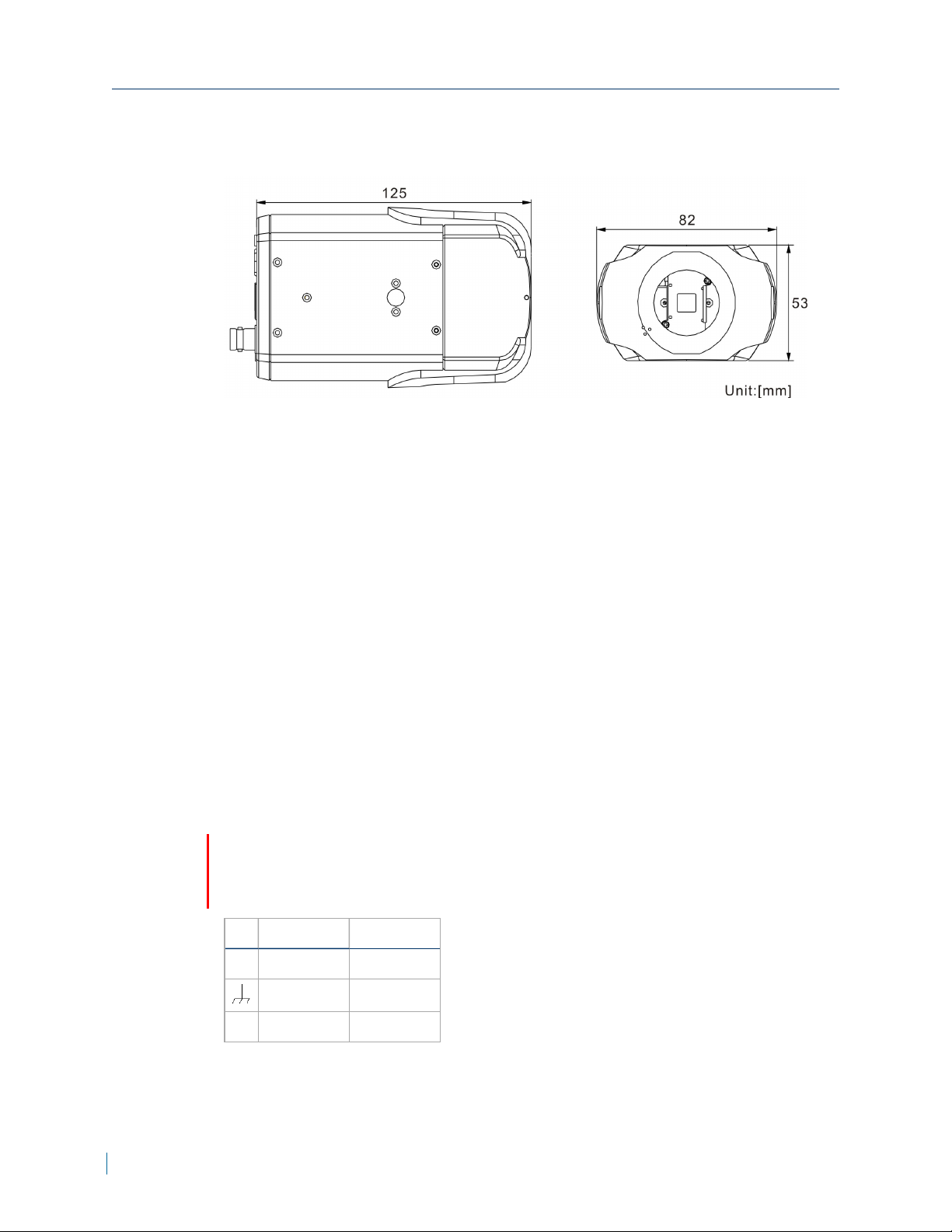
V4320BX-DN Model
V4320BX-DN Model
1/4-20 UNC mounting sockets are available on both sides.
Description
1. Audio LINE OUT and LINE IN /
MIC IN
2. Power LED
3. Reset button
4. Auto IRIS connector
5. RJ-45 Ethernet connector
6. Alarm I/O
7. Video Out
8. MicroSD card slot
9. 12VDC or 24V AC power input
PowerConnections
Caution
Only use a single power source (PoE, 12V DC or 24V AC). Connecting
multiple different power sources can damage the camera.
Pin 24VAC 12VDC
+ Power-1 Power
Earth GND Earth GND
- Power-2 GND
10 © 2014 Verint Systems Inc. All Rights Reserved Worldwide.

Chapter 1: Nextiva V4320Series Overview
I/O Connection
The camera equips one alarm input and one relay output for alarm application.
Description
1. Output +
2. Output -
3. Input +
4. Input -
5. GND
6. RS-485 D-
7. RS-485 D+
Connecting the Lens on the V4320BX
Caution
Verint will not be held liable for damages to persons or property due to the
improper installation of the Nextiva IP cameras.
► To mount and connect the lens
1. Mount the lens by turning it clockwise onto the camera mount until it stops.
2. Connect the lens cable plug to the camera auto-iris connector.
© 2014 Verint Systems Inc. All Rights Reserved Worldwide. 11
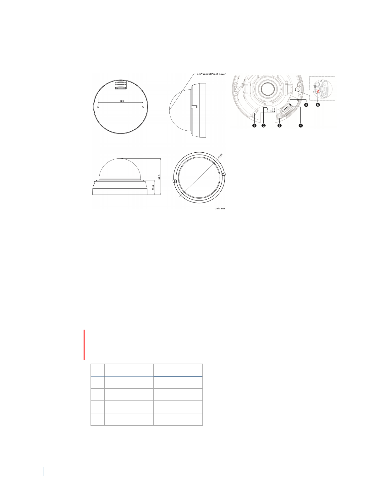
V4320FD-DNModel
V4320FD-DNModel
Description
1. RJ-45 Ethernet connector
2. 24V AC and 12V DC Power
3. Analog Video Out
4. Alarm and Audio I/O
5. Micro SD card slot
6. Reset button
PowerConnections
Caution
Only use a single power source (PoE, 12V DC or 24V AC). Connecting
multiple different power sources can damage the camera.
Pin 24VAC 12VDC
1 AC_1 Not Applicable
2 AC_2 Not Applicable
3 Not Applicable GND
4 Not Applicable 12V DC (+)
12 © 2014 Verint Systems Inc. All Rights Reserved Worldwide.

Chapter 1: Nextiva V4320Series Overview
I/OConnections
The camera equips one alarm input and one relay output for alarm application.
Pin Signal
1 Alarm In -
2 Alarm In +
3 Alarm Out -
4 Alarm Out +
5 Audio Out R
6 Audio Out L
7 Audio GND
8 Audio In R
9 Audio In L
Installing the FDModel
Caution
Verint will not be held liable for damages to persons or property due to the
improper installation of the Nextiva IP cameras.
► To install on a surface
1. Remove the dome cover using supplied security screwdriver.
2. Attach the supplied alignment sticker to the surface.
3. Drill two pilot holes into the surface.
4. Hammer the supplied plastic anchors into the holes.
5. Secure the camera to the ceiling with a screwdriver.
6. Remove the two protective sponge rings protecting the lens and lens hood.
7. Reattach the dome cover.
Note
Insert the micro SDcard into the card slot before turning on the camera. If the
camera is on, reboot the camera after inserting the micro SDcard.
© 2014 Verint Systems Inc. All Rights Reserved Worldwide. 13
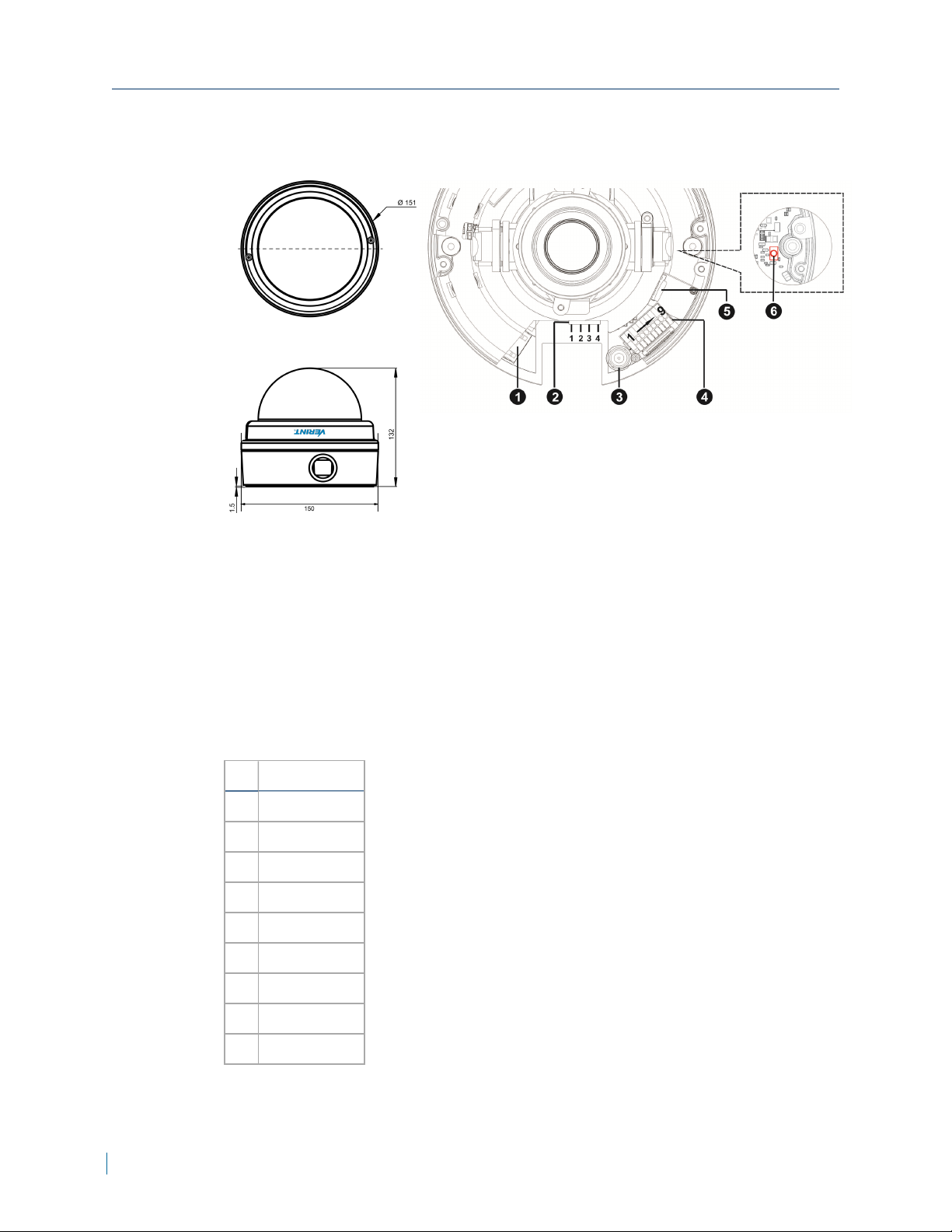
V4320FDW-DNModel
V4320FDW-DNModel
Description
1. RJ-45 Ethernet connector
2. 24V AC and 12V DC
Power
3. Analog video out
4. Alarm and Audio I/O
5. Micro SD card slot
6. Reset button
I/OConnections
The camera equips one alarm input and one relay output for alarm application.
Pin Signal
1 Alarm In -
2 Alarm In +
3 Alarm Out -
4 Alarm Out +
5 Audio Out R
6 Audio Out L
7 Audio GND
8 Audio In R
9 Audio In L
14 © 2014 Verint Systems Inc. All Rights Reserved Worldwide.

Chapter 1: Nextiva V4320Series Overview
PowerConnections
Caution
Only use a single power source (PoE, 12V DC or 24V AC). Connecting
multiple different power sources can damage the camera.
Pin 24VAC 12VDC
1 AC_1 Not Applicable
2 AC_2 Not Applicable
3 Earth GND GND
4 Not Applicable 12V DC (+)
Installation
Caution
Verint will not be held liable for damages to persons or property due to the
improper installation of the Nextiva IP cameras.
Cable gland usage is mandatory if you are installing the camera outdoor to
make the cable entry waterproof unless you are using a ¾ inch NPT pipe.
► To install on a surface
1. Loosen the two security screws using the supplied security torx.
2. Remove the dome cover.
3. Attach the supplied alignment sticker to the surface.
4. Drill four pilot holes that are slightly smaller than the anchors into the
surface.
5. Hammer the supplied plastic anchors into the holes.
6. Secure the metal mount plate to the surface with a screwdriver.
© 2014 Verint Systems Inc. All Rights Reserved Worldwide. 15

Nominal Power Consumption Values
7. Thread all required cables through one of the conduit entries.
For Outdoor
Installation
Using
Cable Gland a. Insert the rubber ring into the cable gland.
Perform the following:
b. Loosen the thread-lock sealing nut of the cable gland.
c. Thread all required cables through the sealing nut and
d. Fasten the gland body to one of the conduit entries.
e. Tighten the thread-lock sealing nut to the gland body.
f. Seal the end of the thread-lock sealing nut with RTV
the gland body.
silicon. Ensure that there are no gaps between the
sealing rubber and the cables.
¾ inch
NPTPipe
8. Connect the cables to the camera.
9. Reattach the camera to the metal mounting plate.
10. Adjust the pan / tilt / spin holders to point the lens at a suitable position for
the desired camera view.
11. Replace the silica gel pack below the BNC connector with the new silica gel
provided to prevent moisture inside the camera.
12. Reattach the dome cover.
a. Apply the Teflon tape to the threads of the pipe.
b. Attach the pipe to the camera conduit entry.
c. Thread all required cables through the pipe.
Nominal Power Consumption Values
The following table lists the nominal power consumption in Watts that the
cameras require to operate under standard conditions. See the "Safety" (page
5).
Nominal Power Consumption System IRLEDs Lens Motor Heaters Total
V4320BX 6.3W N/A N/A N/A 6.3W
V4320FD 5.6W 3.6W 3.2W N/A 12.4W
V4320FDW 5.6W 3.6W 3.2W 7W 19.4W
16 © 2014 Verint Systems Inc. All Rights Reserved Worldwide.

Grounding
For outdoor installation, it is important to ground the installation to protect the
camera against electrical surges. The camera enclosure needs to be grounded
by connecting earth ground to the G pin on the connector block.
If you are using the VPOE-2 housing, refer to the VPOE-2 Housing installation
guide for grounding instruction. Otherwise, connect wire from the Earth
GNDpin to the Earth ground connection to ensure the camera is properly
grounded.
In order to prevent a ground loop:
Use a BNC ground loop isolator in case the BNC video out is used
permanently.
For the FDand FDWmodels, do not connect Earth ground to the camera
power connector.
Do not use shielded Ethernet cables. If using a shielded Ethernet cable, the
shield should not be connected to the camera.
Chapter 1: Nextiva V4320Series Overview
Powering with a 802.3at PoE Injector
This product is intended for indoor use and should be supplied by a UL listed PoE
power supply.
IPCamera Model UL listed power supply required
V4320BX-DN PoE 802.3af class 3 compliant
V4320FD-DN PoE 802.3af class 3 compliant
V4320FDW-DN PoE 802.3at class 4 compliant
► To power with a 802.3at PoE Injector
1. Plug a straight-through Ethernet cable into the RJ-45 connector on the back
of the IP camera.
2. Plug the other end of the cable into a PoE switch or to the Data&PWR port of
a PoE injector. If you use a PoE injector, make sure the Data port of the
injector is properly connected to the Ethernet switch.
Note
Routing of the Ethernet cable from the camera to the power source must be
done inside the building.
© 2014 Verint Systems Inc. All Rights Reserved Worldwide. 17

Powering with a 12VDC Power Supply
Powering with a 12VDC Power Supply
This product is intended for indoor use and should be supplied by a UL listed
power supply.
IPCamera Model UL listed power supply required
V4320BX 12V DC 0.82A or 24V AC 0.41A
V4320FD 12VDC 2.1A or 24VAC 0.91A
V4320FDW 12VDC 2.1A or 24V AC 0.91A
► To power with a 12V DC power supply
1. Connect the power supply cable to the camera.
2. Plug an Ethernet cable into the RJ-45 connector on the back of the IP
camera.
3. Plug the power supply cable to the power outlet.
Caution
In case of battery issues, contact Verint support and return the camera
for a battery replacement. There is a risk of explosion if the battery is
replaced with an incorrect type.
Adjusting the Zoom and Focus
Based on the live image retrieved from the IP camera, you can adjust the field
of view and focus.
► To adjust the zoom and focus
1. Connect the Video Out to a CCTV test monitor.
2. While viewing the image, loosen the zoom and focus controllers.
3. Adjust the zoom factor and focus range.
Note
The lens setup will vary depending on the manufacturer.
4. Tighten the zoom and focus controller.
18 © 2014 Verint Systems Inc. All Rights Reserved Worldwide.

Chapter 1: Nextiva V4320Series Overview
Adjusting the Back Focus
Back Focus refers to the distance from the rear lens element to the camera
focal plane. In most cases, it is required to adjust back focus only when the
camera’s lens cannot hold focus throughout its zoom range.
► To adjust the back focus
1. Set the camera on a stable mount, with the test chart or object at least 75
feet (23 meters) away (or as far as possible).
2. Make sure the iris is wide open. Therefore, it is advised to keep the
environment in low light condition.
3. Adjust the focus to infinite far (∞).
4. Turn the zoom to the extreme telephoto position, and then focus on the
subject.
5. Set the zoom to wide-angle position.
6. Loosen the back focus ring’s retaining screw with the supplied adjuster, and
adjust the back focus ring for sharp picture.
7. Repeat steps 3 ~ 6 until focus can stay the same throughout the zoom
range.
8. Tighten the back focus ring’s retaining screw to fix the ring.
© 2014 Verint Systems Inc. All Rights Reserved Worldwide. 19

Chapter
Once you have connected the IP camera to the network, you can begin
configuring the IP camera to ensure that it can communicate with the attached
devices and with a video management software over the network.
The following topics are discussed:
IP Address Configuration 21
Setting a Static IPAddress 21
Accessing the IP Camera Home Page 23
Viewing Live Video 23
Configuring the General Settings 24
2
Setting Video Formats 25
Setting Video Compression 26
Setting the Video OCX Protocol 26
Setting Video Frame Rate 27
Setting the Video Mask 27
Setting Audio 28

IP Address Configuration
IP Address Configuration
By default, all IPcameras are Dynamic Host Configuration Protocol (DHCP )
enabled. If you have a DHCP server, the device will automatically obtain a valid
IP configuration. If the DHCP configuration fails, the device assigns itself a
temporary IP address based on the Automatic Private IP Addressing (APIPA )
addressing format.
Note
If you plan on using the IPcameras with the Nextiva video management
software, you need to disable the DHCP setting and manually set an IP address
for the device.
The APIPA scheme, available on the Windows operating systems, allows a
device to assign itself a temporary IP address until it receives a complete
network configuration, either manually or from a DHCP server.
A device in APIPA mode does not reside on the same subnet as the other
devices on the IP network. Therefore, it may not be able to view or be visible
by the other devices. All Nextiva edge devices use the following temporary
APIPA configuration:
IP address: 169.254.X.Y (where X and Y are based on the last two octets of
the MAC address of the device)
Subnet mask: 255.255.0.0
Gateway: 169.254.*.*
Setting a Static IPAddress
By default, all Verint devices are Dynamic Host Configuration Protocol (DHCP)
enabled. If you have a DHCP server, the device will automatically obtain a valid
IP configuration. If the DHCP configuration fails, the device assigns itself a
temporary IP address based on the Automatic Private IP Addressing (APIPA )
addressing format.
Note
If you plan on using the device with the Nextiva video management software,
you need to disable the DHCP setting and manually set an IP address for the
device.
The APIPA scheme, available on the Windows operating systems, allows a
device to assign itself a temporary IP address until it receives a complete
network configuration, either manually or from a DHCP server.
21 © 2014 Verint Systems Inc. All Rights Reserved Worldwide.

Chapter 2: Configuration
A device in APIPA mode does not reside on the same subnet as the other
devices on the IP network. Therefore, it may not be able to view or be visible
by the other devices. All Nextiva devices use the following temporary APIPA
configuration:
IP address: 169.254.X.Y (where X and Y are based on the last two octets of
the MAC address of the device)
Subnet mask: 255.255.0.0
Gateway: 169.254.*.*
► To set a static IPaddress
1. Launch the Verint Camera Configurator.
2. In the Discovery tab, click Device Search.
3. From the Discovery table, right-click a device and select Network Setup.
Tip
To set a static IPaddress for multiple devices, press the CTRL key and
click each device.
4. From the Network Setup dialog, perform the following:
a. In the Starting box, type the IP address of the device.
b. In the Subnet Mask box, type the address specifying the subnet in
which the IP address belongs.
c. In the Gateway box, type the IP address of the server that acts as an
access point to another network.
d. Click Apply.
© 2014 Verint Systems Inc. All Rights Reserved Worldwide. 22

Accessing the IP Camera Home Page
Accessing the IP Camera Home Page
Using a web browser such as Microsoft Internet Explorer or Mozilla Firefox, you
can not only view the streaming media, but you can also configure the user
access.
If you are using Mozilla Firefox, the browser will use Apple QuickTime to
stream live video. You can download Apple QuickTime from
http://www.apple.com/quicktime/download/.
Note
The default username and password is admin.
► To access the IPCamera home page
1. In a web browser, type the IP address of the Nextiva IP camera in the
Address bar, and then press ENTER.
Note
If you are using Microsoft Internet Explorer, the first time you connect to the
Nextiva IP cameras, an information bar is displayed requiring you to install
the ActiveX plug-in from Verint Systems Inc. Follow the on-screen instructions
to install the required plug-in.
Viewing Live Video
After connecting to the IPcamera, the first web page to appear is the Home
tab. The Home tab displays the live video feed and allows to perform the
following:
Languages:German, English, Spanish, French, Italian, Korean, Simplified
Chinese and Russian.
Screen Size Adjustment:Image display size can be adjusted to x1/2 and
full screen.
Note
Double-click the screen to close.
Talk:Talk function allows the local site talks to the remote site. Click on the
button to switch it to on / off.
Note
This function is only available for users who have been granted this
privilege by the administrator.
23 © 2014 Verint Systems Inc. All Rights Reserved Worldwide.

Speaker:Click Speaker to mute / activate the audio.
Note
This function is only available for users who have been granted this
privilege by the administrator.
Video Streaming Pause / Restart:Click Stop to disable video
streaming, the live video will be displayed as black. Press restart to show
the live video again.
Configuring the General Settings
► To configure the general settings
1. In a web browser, type the IP address of the IP camera in the Address bar,
and then press ENTER.
2. Type the username and password.
3. Click System.
Chapter 2: Configuration
4. In the Host Name box, type a descriptive name for the device.
5. From the Time Zone list, select the time zone.
6. Select Enable daylight saving time if the location you are in observes
DST. Set the time offset and DST duration. The format for time offset is
[hh:mm:ss].
7. In the Time format list, select the date format.
8. Select one of the following:
Sync with computer time: Date and time is synchronized with a
computer.
Manually: Enter the date and time manually.
Sync with NTPserver: Date and time is synchronized with a Network
Time Protocol (NTP) server. in the NTP server box, type the IPaddress
of the NTPserver and select the update interval .
Note
The synchronization is performed every time the camera boots up.
9. Click Save.
© 2014 Verint Systems Inc. All Rights Reserved Worldwide. 24

Setting Video Formats
Setting Video Formats
► To set the video format
1. In a web browser, type the IP address of the IP camera in the Address bar,
and then press ENTER.
2. Type the username and password.
3. Click Video.
4. From the Video Resolution section, select H.264 or H.264 + H.264.
a. Set the resolution and frame rate for each encoder.
b. Click Save.
5. From the Text Overlay Settings section, select the items to display on the
live video pane on the live video pane.
a. Select Include Date to display the date
b. Select Include Time to display the time
c. Select Include text string and type the text to display. The maximum
length of the string is 20 alphanumeric characters.
d. Click Save.
6. From the Video Rotate Type section, select how to display video display
type if necessary. Selectable video rotate types include:
Normal
Flip
Mirror
90 degree clockwise
180 degree rotate
90 degree counterclockwise.
7. From the GOV Settings section, set the GOV length to determine the frame
structure (I-frames and P-frames) in a video stream for saving bandwidth.
The setting range is from 2 to 64 and the default value is 60, which means
there are one I-frame every 60 frames. GOVLength values and click Save.
8. From the H.264 Profile section, set the profiles to use for H.264-1 and
H.264-2 and click Save.
25 © 2014 Verint Systems Inc. All Rights Reserved Worldwide.

Setting Video Compression
► To set video compression
1. In a web browser, type the IP address of the IP camera in the Address bar,
and then press ENTER.
2. Type the username and password.
3. Click Video >Video Compression.
4. From the H.264-1 and H.264-2 compression settings sections, set the
bit rate for H.264-1 and H.264-2.
5. From the CBR Mode Settings section, select to enable CBR mode for
H.264-1 or H.264-2.
Note
If CBRis not selected, then VBR is used. In CBR mode the video encoder
will cap the bit rate up to the configured bit rate.
6. Click Save for each option.
Chapter 2: Configuration
Setting the Video OCX Protocol
► To set video OCXprotocol
1. In a web browser, type the IP address of the IP camera in the Address bar,
and then press ENTER.
2. Type the username and password.
3. Click Video >Video OCXProtocol.
4. From the Video OCXprotocol settings sections, select one of the
following:
RTP over UDP
RTP over RTSP(TCP)
RTSP over HTTP
Multicast Mode:
Type the multicast IP address.
For H.264-1 and H.264-2, type the multicast Video Port.
Type the Multicast Audio Port.
Type the Multicast TTL.
5. Click Save for each option.
© 2014 Verint Systems Inc. All Rights Reserved Worldwide. 26

Setting Video Frame Rate
Note
For video in the web page to pass through a NAT router, RTSP over HTTP must
be set.
The OCX protocol is only applicable to stream video to the web page and not
Nextiva VMS.
Setting Video Frame Rate
► To set video frame rate
1. In a web browser, type the IP address of the IP camera in the Address bar,
and then press ENTER.
2. Type the username and password.
3. Click Video >Video Frame Rate.
4. From the H.264-1 or H.264-2 frame rate settings sections, set the
frame rate to the desired value.
5. Click Save for each option.
Note
Lower frame rate will decrease video smoothness.
Setting the Video Mask
► To set the video mask
1. In a web browser, type the IP address of the IP camera in the Address bar,
and then press ENTER.
2. Type the username and password.
3. Click Video >Video Mask.
4. From the Active Mask Function section, select the Video Mask to display
in the Live Video pane. Use the mouse to adjust the size and location.
5. From the Maks Setting section, select a color for the mask. Mask color
include red, black, white, yellow, green, blue, cyan, and magenta.
6. Click Save for each option.
27 © 2014 Verint Systems Inc. All Rights Reserved Worldwide.

Setting Audio
► To set audio
1. In a web browser, type the IP address of the IP camera in the Address bar,
and then press ENTER.
2. Type the username and password.
3. Click Video >Audio.
4. From the Transmission Mode sections, select one of the following:
Full-duplex (Talk and Listen simultaneously):In the Full-duplex mode,
the local and remote sites can communicate with each other
simultaneously, i.e. both sites can speak and be heard at the same time.
Half-duplex (Talk or Listen, not at the same time):In the Half-duplex
mode, the local / remote site can only talk or listen to the other site at a
time.
Simplex (Talk only):In the Talk only Simplex mode, the local / remote
site can only talk to the other site.
Chapter 2: Configuration
Simplex (Listen only):In the Listen only Simplex mode, the local /
remote site can only listen to the other site.
Disable:Select the item to turn off the audio transmission function.
5. From the Server Gain Setting section, set the audio input/output gain
levels for sound amplification. The values are adjustable as follows:
Output Gain: 1 to 6
Input Gain: 1 to 10.
6. Click Save for each option.
© 2014 Verint Systems Inc. All Rights Reserved Worldwide. 28

Chapter
The following topics are discussed:
Configuring Exposure 30
Configuring the White Balance 30
Adjusting the Picture Quality 31
Adjusting the Digital Zoom 32
Adjusting the IR 32
Adjusting the Noise Reduction 33
Setting the TVSystem 33
3

Configuring Exposure
Configuring Exposure
► To configure the exposure
1. In a web browser, type the IP address of the IP camera in the Address bar,
and then press ENTER.
2. Type the username and password.
3. Click Camera >Camera - Exposure.
4. In the Max Gain list, select a value.
5. Select one of the following:
P-Iris:In this mode, the minimum iris opening is limited to affect the
exposure. The minimum iris opening can be adjusted from F4.8 to F8.6.
Iris Priority:In this mode, it is the iris that has premier priority in
control of the exposure. The value of iris is adjustable from F1.6 to F28.
In WDR Multiple shutter list, select the desired shutter mode.
Note
It is recommended to keep the default option, WDR first to maintain
optimal WDR performance.
6. In Min Shutter Speed list, set the minimum shutter speed that camera can
use. By default it is set to 1/30 to allow 30 fps.
Note
Going lower then 1/30 will affect the maximum frame rate.
7. Click ü.
Configuring the White Balance
A camera needs to find reference color temperature, which is a way of
measuring the quality of a light source, for calculating all the other colors. The
unit for measuring this ratio is in degree Kelvin (K). You can select one of the
White Balance Control modes according to the operating environment. The
following table shows the color temperature of some light sources for
reference.
Light Sources Color Temperature in degree Kelvin (K)
Cloudy Sky 6,000 to 8,000
Noon Sun and Clear Sky 6,500
Household Lighting 2,500 to 3,000
75-watt Bulb 2,820
30 © 2014 Verint Systems Inc. All Rights Reserved Worldwide.

Chapter 3: Configuring Video Quality
Light Sources Color Temperature in degree Kelvin (K)
Candle Flame 1,200 to 1,500
► To configure the white balance
1. In a web browser, type the IP address of the IP camera in the Address bar,
and then press ENTER.
2. Type the username and password.
3. Click Camera >White Balance.
4. Select one of the following:
Auto: The Auto Balance White mode is suitable for environment with light
source having color temperature in the range roughly from 2700 to
7500K.
ATW: ATW Mode (Auto Tracing White Balance) The IPCamera takes out
the signals in a screen in the range from 2500 K to 10000 K.
Manual: You can change the White Balance value manually via specifying
R gain and B gain; the range of R/B gain is from 0 to 255.
Adjusting the Picture Quality
► To adjust the picture quality
1. In a web browser, type the IP address of the IP camera in the Address bar,
and then press ENTER.
2. Type the username and password.
3. Click Camera >Picture Adjustment.
4. In the Brightness list, select a value from 1 to 25. To increase video
brightness, select a bigger number.
5. Click ü.
6. In the Sharpness list, select a value from -15 to 10 to set the image
sharpness.
7. Click ü.
8. In the Contrast list,select a value from -13 to 12.
9. Click ü.
10. In the Saturation list, select a value from -13 to 12.
11. Click ü .
12. In the Hue list, select a value from 1 to 12.
13. Click ü .
© 2014 Verint Systems Inc. All Rights Reserved Worldwide. 31

Adjusting the Digital Zoom
Adjusting the Digital Zoom
► To adjust the digital zoom
1. In a web browser, type the IP address of the IP camera in the Address bar,
and then press ENTER.
2. Type the username and password.
3. Click Camera >Digital Zoom.
4. In the Digital Zoom list, select Night, Day or the zoom factor x2 x3 x4 x5
x6 x7 x8.
5. Click ü.
Adjusting the IR
With the IR cut filter, the Camera can still catch clear image at night time or in
low light conditions.
► To adjust the IR
1. In a web browser, type the IP address of the IP camera in the Address bar,
and then press ENTER.
2. Type the username and password.
3. Click Camera >IRFunction.
4. In the IRFunction list, select Auto, On, Off, Light Sensor, Light On, Light
Off or Smart.
Note
Light Sensor, Light On, Light Off are only available on cameras with a builtin IR LED module.
5. Click ü.
32 © 2014 Verint Systems Inc. All Rights Reserved Worldwide.

Chapter 3: Configuring Video Quality
Adjusting the Noise Reduction
3D Noise Reduction function to allow the processor analyzes pixel by pixel and
frame by frame to eliminate environmental noise signal so that the highest
quality image can be produced even in low light conditions
► To adjust the noise reduction
1. In a web browser, type the IP address of the IP camera in the Address bar,
and then press ENTER.
2. Type the username and password.
3. Click Camera >3DNR or Camera >2DNR
4. In the Noise Reduction list, select Off, Low, Middle or High.
5. Click ü.
Setting the TVSystem
► To set the TVSystem
1. In a web browser, type the IP address of the IP camera in the Address bar,
and then press ENTER.
2. Type the username and password.
3. Click Camera >TVSystem.
4. In the TVSystem list, select the video format that matches the TV system
(NTSC or PAL).
5. Click ü.
© 2014 Verint Systems Inc. All Rights Reserved Worldwide. 33

Chapter
The System configuration page is only accessible by the Administrator and
allows them to configure advanced parameters.
The following topics are discussed:
Configuring the User Settings 35
Configuring HTTPS 36
Creating an IP Filter 37
Configuring IEEE 802.1X 38
Configuring the Network Settings 38
4
Configuring Quality of Service 40
Configuring SNMP 40
Configuring UPnP 41
Configuring Mail 42
Configuring FTP 43
Configuing HTTP 43
Configuring Alarm Inputs 44
Configuring Motion Detection 45
Configuring Network Failure Detection 46
Setting the Tampering Alarm 47
Setting the Periodical Event 48
Formatting the SD Card 49
Configuring the SD Card 50
Configuring Local Recording 51
Configuring a Schedule 51
Configuring the File Location 52
Adjusting the Iris 52
Viewing Information 53
Performing a Factory Default 53
Performing a Firmware Upgrade 54

Configuring the User Settings
Exporting or Uploading Configuration Files 54
Configuring the User Settings
► To configure the user settings
1. In a web browser, type the IP address of the IP camera in the Address bar,
and then press ENTER.
2. Type the username and password.
3. Click System >Security >User.
4. In the Admin passwordbox, type a new administrators password. Retype
the password in the Confirm password box.
Note
The password can be up to 14 characters long and contain the following: AZ, a-z, 0-9, !#$%&’-.@^_~.
5. In the Add User section, perform the following:
a. In the User name box, type a new user name.
b. In the User password box, type the password for the user.
c. Select the user privileges :
I/O access:Allows users to view video when accessing to the camera.
Camera control: Allows users to change camera parameters on the
Camera Setting page.
Talk and Listen: Allows users in the local site (PC site) to
communicate with users in the remote site.
Note
You can have a maximum of 20 users and both the user name and
password can be up to 16 characters.
6. Click Save.
35 © 2014 Verint Systems Inc. All Rights Reserved Worldwide.

Configuring HTTPS
HTTPS provides a secure connections between the IP Camera and web browser
using Secure Socket Layer (SSL) or Transport Layer Security (TLS).
A self-signed certificate or a CA-signed certificate is required to implement
HTTPS.
► To create a self-signed certificate
1. In a web browser, type the IP address of the IP camera in the Address bar,
and then press ENTER.
2. Type the username and password.
3. Click System >Security >HTTPS.
4. Click Create to create and install a self-signed certificate.
1. In the Country box, type the two-letter combination to denote the
country where the certificate will be used. The letter combination must
be according to the ISO 3166 standard. For more information on ISO
3166, visit http://www.iso.org/iso/country_codes.htm.
Chapter 4: Advance Configuration
2. In the State box, type the state or province name.
3. In the Locality box, type the locality name.
4. In the Organization box, type the organization name.
5. In the Organization Unit box, type the organization unit name.
6. In the Common Name box, type the IP address or hostname of the
Edge device.
7. In the Valid days box, type the number of day to keep the certificate
valid.
8. Click OK.
© 2014 Verint Systems Inc. All Rights Reserved Worldwide. 36

Creating an IP Filter
► To install a signed certificate
1. In a web browser, type the IP address of the IP camera in the Address bar,
and then press ENTER.
2. Type the username and password.
3. Click System >Security >HTTPS.
4. Click Create Certificate Requestto create a signed certificate request
1. In the Country box, type the two-letter combination to denote the
2. In the State box, type the state or province name.
3. In the Locality box, type the locality name.
4. In the Organization box, type the organization name.
5. In the Organization Unit box, type the organization unit name.
6. In the Common Name box, type the IP address or hostname of the
country where the certificate will be used. The letter combination must
be according to the ISO 3166 standard. For more information on ISO
3166, visit http://www.iso.org/iso/country_codes.htm.
Edge device.
7. Click OK.
5. Click Properties below the Subject field and copy the PEM-formatted
request and send it to the selected CA.
6. When the signed certificate is returned, click Browse and locate the signed
certificate.
Creating an IP Filter
► To create an IPfilter
1. In a web browser, type the IP address of the IP camera in the Address bar,
and then press ENTER.
2. Type the username and password.
3. Click System >Security >IPfilter.
4. Select Enable IPfilter.
5. Select Allow or Deny.
6. Click Apply.
7. Type the ip addresses to allow or deny and click Add.
37 © 2014 Verint Systems Inc. All Rights Reserved Worldwide.

Configuring IEEE 802.1X
► To configure IEEE802.1X
1. In a web browser, type the IP address of the IP camera in the Address bar,
and then press ENTER.
2. Type the username and password.
3. Click System >Security >IEEE 802.1X.
4. For CACertificate, click Browse and locate the CACertificate.
5. Click Upload.
6. For ClientCertificate, click Browse and locate the client certificate.
7. Click Upload.
8. For Private Key, click Browse and locate the private key.
9. Click Upload.
10. In the Settings, set the following:
1. Identity:user identity associated with the certificate.
Chapter 4: Advance Configuration
2. Private Key Password:The user password.
11. Select Enable IEEE 802.1X.
12. Click Save.
Configuring the Network Settings
► To configure the network settings
1. In a web browser, type the IP address of the IP camera in the Address bar,
and then press ENTER.
2. Type the username and password.
3. Click System >Network >Basic.
4. Select one of the following:
Get IPAddress automatically
Use fixed IP address
Use PPPoE
© 2014 Verint Systems Inc. All Rights Reserved Worldwide. 38

Configuring the Network Settings
5. If you select Use fixed IP address, compete the following:
a. In the IP Address box, type the IP address for the device.
b. In the Subnet Mask box, type the mask to determine what subnet the
IP address belongs.
c. In the Default Gateway box, type the IP address of the server that acts
as an access point to another network. You can obtain the IP address of
the default gateway by asking the network administrator.
d. In the Primary and Secondary DNS boxes, type the IPaddresses of
the Primary and Secondary DNS.
6. If you select PPPoE, compete the following:
a. In the User name box, type the name of the connecting user.
b. In the Password box, type the password of the user.
7. In the Web Server port box, type the port number used by the web
server. The default is 80.
8. In the RTSPport box, type the port number used by the RTSP server. The
default is 554.
9. In the HTTPSport box, type the port number used by the HTTPS server.
The default is 443.
10. Select Enable IPv6 if you use IPv6.
11. Click Save.
39 © 2014 Verint Systems Inc. All Rights Reserved Worldwide.

Chapter 4: Advance Configuration
Configuring Quality of Service
Quality of Service (QoS) provides differentiated service levels for different
types of traffic packets, which guarantees delivery of priority services
especially when network congestion occurs.
► To configure QoS
1. In a web browser, type the IP address of the IP camera in the Address bar,
and then press ENTER.
2. Type the username and password.
3. Click System >Network >QoS.
4. In the Video DSCP box, type a value from 0 to 63.
5. In the Audio DSCP box, type a value from 0 to 63.
6. In the Management DSCP box, type a value from 0 to 63.
7. Click Save.
Note
To enable this function,the switches and routers in the network must support
QoS.
Configuring SNMP
► To configure SNMP
1. In a web browser, type the IP address of the IP camera in the Address bar,
and then press ENTER.
2. Type the username and password.
3. Click System >Network >SNMP.
4. Select one of the following:
Enable SNMP v1
Enable SNMPv2
5. In the Read Community box, type the name of the community name that
has read-only access to all supported SNMP objects. The default value is
public.
6. In the Write Community box, type the name of the community name that
has read / write access to all supported SNMP objects (except read-only
objects). The default value is write.
7. In the Security Name box, type a security name.
© 2014 Verint Systems Inc. All Rights Reserved Worldwide. 40

Configuring UPnP
8. In the Authentication Type list, select the authentication algorithm for
9. In the Authentication Password box, type a password for the user.
10. In the Encryption Type list, select the privacy protocol to encrypt the
11. In the Encryption Password box, type a password for the privacy
12. Select Enable Traps to send massages to a management system for
SNMP requests. You can select from the following:
MD5:The Message Digest Version 5 (MD5) hash function is used to
determine that the message is from a valid source.
SHA:The Secure Hash Algorithm (SHA) has function is used to
determine that the message is from a valid source
contents of the data. You can select from the following:
DES:The Data Encryption Standard (DES) algorithm is used to encrypt
the data.
AES:The Advanced Encryption Standard (AES) algorithm is used to
encrypt the data.
protocol.
important events or status changes.
13. In the Trap address box, type the IP address of the management server.
14. In the Trap community box, type the community to use when sending a
trap message to the management system.
15. Select Warm Start to signifies that the SNMP device performs software
reload.
16. Click Save.
Configuring UPnP
► To configure UPnP
1. In a web browser, type the IP address of the IP camera in the Address bar,
and then press ENTER.
2. Type the username and password.
3. Click System >Network >UPnP.
4. Select Enable UPnP.
Note
To enable this function, a UPnP component must be installed on the
computer.
5. Select Enable UPnP port forwarding to allow the IP Camera to open the
41 © 2014 Verint Systems Inc. All Rights Reserved Worldwide.

web server port on the router automatically.
Note
To enable this function, verify that the router supports UPnP and it is
activated.
6. In the Friendly name box, type the name for the IP Camera for identity.
7. Click Save.
Configuring Mail
The Administrator can send an e-mail via Simple Mail Transfer Protocol (SMTP)
when an alarm is triggered. SMTP is a protocol for sending e-mail messages
between servers. SMTP is a relatively simple, text-based protocol, where one
or more recipients of a message are specified and the message text is
transferred.
► To configure mail
Chapter 4: Advance Configuration
1. In a web browser, type the IP address of the IP camera in the Address bar,
and then press ENTER.
2. Type the username and password.
3. Click System > Mail.
4. In the 1st SMTP(mail)server box, type the name of the mail server.
5. In the 1st SMTP(mail)server port box, type the port number of the mail
server. The default value is 25.
6. In the 1st SMTPaccountname box, type the user account name.
7. In the 1st SMTPpassword box, type the password.
8. In the 1st recipient email address box, type the email address of the
recipient.
9. Select 1st SMTPSSL to use SSL.
10. In the 2nd SMTP(mail)server box, type the name of the mail server.
11. In the 2nd SMTP(mail)server port box, type the port number of the
mail server. The default value is 25.
12. In the 2nd SMTPaccountname box, type the user account name.
13. In the 2nd SMTPpassword box, type the password.
14. In the 2nd recipient email address box, type the email address of the
recipient.
15. Select 2nd SMTPSSL to use SSL.
16. Click Save.
© 2014 Verint Systems Inc. All Rights Reserved Worldwide. 42

Configuring FTP
Configuring FTP
The Administrator can set sending alarm message to a specific File Transfer
Protocol (FTP) site when an alarm is triggered. Users can assign alarm
message to up to two FTP sites. Enter the FTP details, which include server,
server port, user name, password and remote folder, in the fields.
► To configure FTP
1. In a web browser, type the IP address of the IP camera in the Address bar,
and then press ENTER.
2. Type the username and password.
3. Click System > FTP.
4. In the 1st FTPserver box, type the name of the FTP server.
5. In the 1st FTPserver port box, type the port number of the FTP server.
The default value is 21.
6. In the 1st FTPusername box, type the user name.
7. In the 1st FTP password box, type the password.
8. In the 1st FTPremote folder box, type the name of the remote folder.
9. Select 1st FTPpassive mode to use passive mode.
10. In the 2nd FTPserver box, type the name of the FTP server.
11. In the 2nd FTPserver port box, type the port number of the FTP server.
The default value is 21.
12. In the 2nd FTPusername box, type the user name.
13. In the 2nd FTP password box, type the password.
14. In the 2nd FTPremote folder box, type the name of the remote folder.
15. Select 2nd FTPpassive mode to use passive mode.
16. Click Save.
Configuing HTTP
► To configure HTTP
1. In a web browser, type the IP address of the IP camera in the Address bar,
and then press ENTER.
2. Type the username and password.
3. Click System > HTTP.
4. In the 1st HTTPserver box, type the name of the HTTPserver.
5. In the 1st HTTPuser name box, type the user name.
43 © 2014 Verint Systems Inc. All Rights Reserved Worldwide.

6. In the 1st HTTPpassword box, type the password.
7. In the 2nd HTTPserver box, type the name of the HTTPserver.
8. In the 2nd HTTPuser name box, type the user name.
9. In the 2nd HTTPpassword box, type the password.
10. Click Save.
Configuring Alarm Inputs
The camera comes with one alarm input and one relay output for
communicating with alarm systems to catch events.
► To configure alarm inputs
1. In a web browser, type the IP address of the IP camera in the Address bar,
and then press ENTER.
2. Type the username and password.
3. Click System > Events> Alarm input.
Chapter 4: Advance Configuration
4. From the Alarm Switch list, select On , Off or By Schedule.
If you select By Schedule, from the list, select the schedules to run.
ON: System generates events based on the input state.
OFF: System will never generate events based on alarm input state.
Schedule:System will only generate events based on alarm input state
when schedule is ON.
5. From the Alarm Type list, select Normal Open or Normal Close.
Normal Close: Events will not be generated when the alarm input is
closed. This is the normal situation. An alarm will be generated when the
alarm input will be opened.
Normal Open:Events are generated when the alarm input is opened.
6. From the Triggered Action section, select the alarm actions to perform.
Choose from the following:
Enable Alarm Output
Send Message by FTP/E-Mail
IR cut filter (on/off)
Upload image by FTP
Upload image by E-Mail
Send HTTPnotification
7. Click Save.
© 2014 Verint Systems Inc. All Rights Reserved Worldwide. 44

Configuring Motion Detection
Configuring Motion Detection
Motion Detection function allows detecting suspicious motion and triggering
alarms when motion volume in the detected area reaches / exceeds the
determined sensitivity threshold value.
The function supports up to four sets of Motion Detection Settings.
► To configure alarm inputs
1. In a web browser, type the IP address of the IP camera in the Address bar,
and then press ENTER.
2. Type the username and password.
3. Click System > Events > Motion Detection.
4. From the Motion Detection list, select the motion set.
5. Select On , Off or By Schedule.
If you select By Schedule, from the list, select the schedules to run.
6. From the Motion Detection Setting section, set the following:
Sampling pixel interval.
Detection level
Sensitivity level
Time interval
7. Click Add to add a motion detection window on the live video pane. You can
add up to ten windows in each set of Motion detection settings.
8. To change the size of the Motion Detection Window, move the mouse cursor
to the edge of the frame and draw it outward / inward. Moving the mouse to
the center of the frame can shift the frame to the intended location.
9. From the Triggered Action section, select the alarm actions to perform.
Choose from the following:
Enable Alarm Output (low/high)
Send Message by FTP/E-Mail
Send HTTPnotification
Upload image by FTP
Upload image by E-Mail
10. Click Save.
45 © 2014 Verint Systems Inc. All Rights Reserved Worldwide.

Chapter 4: Advance Configuration
Note
When motion detection is set and saved, a motion activity window is
displayed. This motion activity window shows the motion level. The blue line is
the motion level and the red line is the motion threshold. This motion activity
window is useful to help motion detection settings (Detection level, Sensitivity
level, sampling pixel) based on your specific scene.
Configuring Network Failure Detection
Network Failure Detection allows the IP Camera to ping another IP device (e.g.
NVR, VSS, Video Server, etc.) within the network periodically and generates
some actions in case of network failure occurs, for instance, a Video Server is
somehow disconnected.
► To configure network failure detection
1. In a web browser, type the IP address of the IP camera in the Address bar,
and then press ENTER.
2. Type the username and password.
3. Click System > Events > Network failure detection.
4. Select On , Off or By Schedule.
If you select By Schedule, from the list, select the schedules to run.
5. From the Detection Type section, set the IPaddress to ping and the
interval.
6. From the Triggered Action section, select the alarm actions to perform.
Choose from the following:
Enable Alarm Output (low/high)
Send Message by FTP/E-Mail
7. Click Save.
© 2014 Verint Systems Inc. All Rights Reserved Worldwide. 46

Setting the Tampering Alarm
Setting the Tampering Alarm
► To set tampering alarm
1. In a web browser, type the IP address of the IP camera in the Address bar,
and then press ENTER.
2. Type the username and password.
3. Click System > Events > Tampering.
4. Select On , Off or By Schedule.
If you select By Schedule, from the list, select the schedules to run.
5. From the Tampering Duration box, set the number of seconds to wait
before triggering a tampering alarm. The time range is from 10 to 3600
seconds and the default value is 20 seconds.
6. From the Triggered Action section, select the alarm actions to perform.
Choose from the following:
Enable Alarm Output (low/high)
Send Message by FTP/E-Mail
Send HTTPnotification.
Upload image by FTP
Upload image by E-Mail
7. Click Save.
47 © 2014 Verint Systems Inc. All Rights Reserved Worldwide.

Setting the Periodical Event
► To set Periodical Event
1. In a web browser, type the IP address of the IP camera in the Address bar,
and then press ENTER.
2. Type the username and password.
3. Click System > Events > Periodical Event.
4. Select On or Off.
5. In the Minimum interval box, type the minimal time interval in seconds.
6. From the Triggered Action section, select the alarm actions to perform.
Choose from the following:
Trigger Action Perform the following
Chapter 4: Advance Configuration
Upload image by
FTP
Upload image by Email
7. From the File Name section, set the properties of the image file.
8. In the File name box, type a name for the image.
9. Select one of the following:
Add date/time suffix.
Add sequence number suffix (no maximum value).
Add sequence number suffix up to and then start over.
1. From the FTPAddress list, select the FTPsite.
2. From Pre-trigger buffer list, select the number
of frames.
3. From the Post-trigger buffer list, select the
number of frames.
1. From the E-mail Address list, select the e-mail
address.
2. From Pre-trigger buffer list, select the number
of frames.
3. From the Post-trigger buffer list, select the
number of frames.
Overwrite.
10. Click Save.
© 2014 Verint Systems Inc. All Rights Reserved Worldwide. 48

Formatting the SD Card
Formatting the SD Card
You can record video and audio to a micro SD card inserted in the camera. The
IPcameras support a micro SD (SDHC or SDXC) card up to 64GB.
When using the SD card for the first time, you must use the camera web page
to format the SDcard with the ext4 file system. Once formatted, content on the
SDcard can only be accessed via the web page or by inserting the SDcard in a
Linux based system.
For more information on SDcard life expectancy, refer to the product bulletin
on SDCard Life Expectancy.
Note
All content on the SD card will be lost after formatting.
► To format the SDcard
1. Insert a SDcard.
2. In a web browser, type the IP address of the IP camera in the Address bar,
and then press ENTER.
3. Type the username and password.
4. Click System > Storage management.
5. Click Format.
Caution
This process can take up to five minutes. Do not reboot the camera
during formatting.
Once completed, Device Type should display SD card – ext4 and status
display Yes.
49 © 2014 Verint Systems Inc. All Rights Reserved Worldwide.

Configuring the SD Card
Use the Storage Management tab from the web page to view storage status and
configuration of the SD card.
► To configure local recording
1. In a web browser, type the IP address of the IP camera in the Address bar,
and then press ENTER.
2. Type the username and password.
3. Click System > Storage management.
4. Select Enable automatic disk cleanup to remove video based on the
time and storage limit.
Note
If automatic disk cleanup is not enabled, the recording will stop when the
SD card gets full.
5. Set the number of days or weeks to wait before deleting video.
Chapter 4: Advance Configuration
6. Set the percentage of disk space used before deleting the oldest video.
Note
To extend the life expectancy of the SD card, Verint recommends setting
the disk cleanup to 85% or lower as per SD card manufacturer
recommnedations.
7. Click Save.
Note
First disk clean up is done based on the number of days or week set. If the
SD card is still over the maximum percentage, clean up will be done by
deleting the oldest files (up to seven files at the same time).
8. From the recording list section, you can view, sort, remove and download
individual video files.
© 2014 Verint Systems Inc. All Rights Reserved Worldwide. 50

Configuring Local Recording
Configuring Local Recording
In the Recording setting page, you can specify the recording schedule that fits
the present surveillance requirement.
► To configure local recording
1. In a web browser, type the IP address of the IP camera in the Address bar,
and then press ENTER.
2. Type the username and password.
3. Click System > Recording.
4. From the Recording Schedule select one of the following: Disable,
Always or Only during time frame.
5. If you select Only during time frame, select the days to record, the Start
time and the duration of the recording.
6. Click Save.
Configuring a Schedule
This function allows the users to setup schedules for Alarm Switch, Motion
Detection and Network Failure Detection. You can create up to 10 sets of
time frames in the time frame list.
► To configure a schedule
1. In a web browser, type the IP address of the IP camera in the Address bar,
and then press ENTER.
2. Type the username and password.
3. Click System > Schedule.
4. For each set, select the days to record, the Start time and the duration of
the recording.
5. Click Save.
51 © 2014 Verint Systems Inc. All Rights Reserved Worldwide.

Configuring the File Location
Users can specify a storage location on the PC or in the hard drive for the
snapshots and live video recording. The default setting is: C:\.
► To configure file location
1. In a web browser, type the IP address of the IP camera in the Address bar,
and then press ENTER.
2. Type the username and password.
3. Click System > File location.
4. Click Select and choose the location where you want to save snapshots and
live video recording.
5. Click Save.
Note
If you are using Windows 7, you must log in as an Administrator to implement
the Snapshot and Web Recording function.
Chapter 4: Advance Configuration
Adjusting the Iris
► To adjust the iris
1. In a web browser, type the IP address of the IP camera in the Address bar,
and then press ENTER.
2. Type the username and password.
3. Click System > Iris Adjustment.
4. Follow the on-screen instructions.
© 2014 Verint Systems Inc. All Rights Reserved Worldwide. 52

Viewing Information
Viewing Information
► To view information
1. In a web browser, type the IP address of the IP camera in the Address bar,
and then press ENTER.
2. Type the username and password.
3. Click System > View information.
4. Click Log file to view system logs.
5. Click User information to view information about the users.
6. Click Parameters to view information about the current settings of the
IPcamera.
7. Click Access list to view access information.
Performing a Factory Default
The IP camera comes with the following factory default values:
IP Address: DHCP enabled. If the DHCP configuration fails, the IP camera
assigns itself a temporary APIPA address: 169.254.X.Y. (where X and Y are
based on the last two octets of the MAC Address.
Username and Password: admin
► To perform a factory default
1. In a web browser, type the IP address of the IP camera in the Address bar,
and then press ENTER.
2. Type the username and password.
3. Click System > Maintenance.
4. From the Factory Default section, click one of the following:
Full Restore:To completely restore to the factory default settings.
Partial Restore: keeps network configuration.
Note
Click Reboot to restart the IPcamera without changing current settings.
53 © 2014 Verint Systems Inc. All Rights Reserved Worldwide.

Chapter 4: Advance Configuration
Performing a Firmware Upgrade
► To perform a firmware upgrade
1. In a web browser, type the IP address of the IP camera in the Address bar,
and then press ENTER.
2. Type the username and password.
3. Click System > Maintenance.
4. From the Upgrade section, perform the following:
a. From Step 1, click Browse and locate the firmware file to upload to the
IPcamera.
Caution
Do not change the file name, or the IPcamera will not find the file.
b. From Step 2, select the firmware file (4320_FW_xx_yy) to install.
c. From Step 3, click Upgrade.
Exporting or Uploading Configuration Files
Users can export configuration files to a specified location and retrieve data by
uploading an existing configuration file to the IP Camera.
► To export or upload configuration files
1. In a web browser, type the IP address of the IP camera in the Address bar,
and then press ENTER.
2. Type the username and password.
3. Click System > Maintenance.
4. From the Maintenancesection, perform one the following:
Click Export to save system settings by exporting the configuration file
(.bin) to a specified location for future use.
Click Browse to select an existing configuration file , and then click
Upload.
Note
The IP address is also exported. If the configuration is imported into another
camera, the camera will have the same IP address as the camera used to
export the configuration.
© 2014 Verint Systems Inc. All Rights Reserved Worldwide. 54

For more information, please visit us at http://www.verint.com/solutions/video-situation-
intelligence/index.html
Americas: info@verint.com
EMEA: marketing.emea@verint.com
APAC: marketing.apac@verint.com
All other trademarks and product names are the property of their respective owners.
The information in this document may be superseded by subsequent documents.
 Loading...