

Verint Nextiva S5120FD Quick Installation Manual
Nextiva S5100 - FD Models
Quick Installation Guide
All users should read the user manuals for complete details on installation, usage and functionality.
Hardware Overview
The S5120FD features a 2-Megapixel sensor.
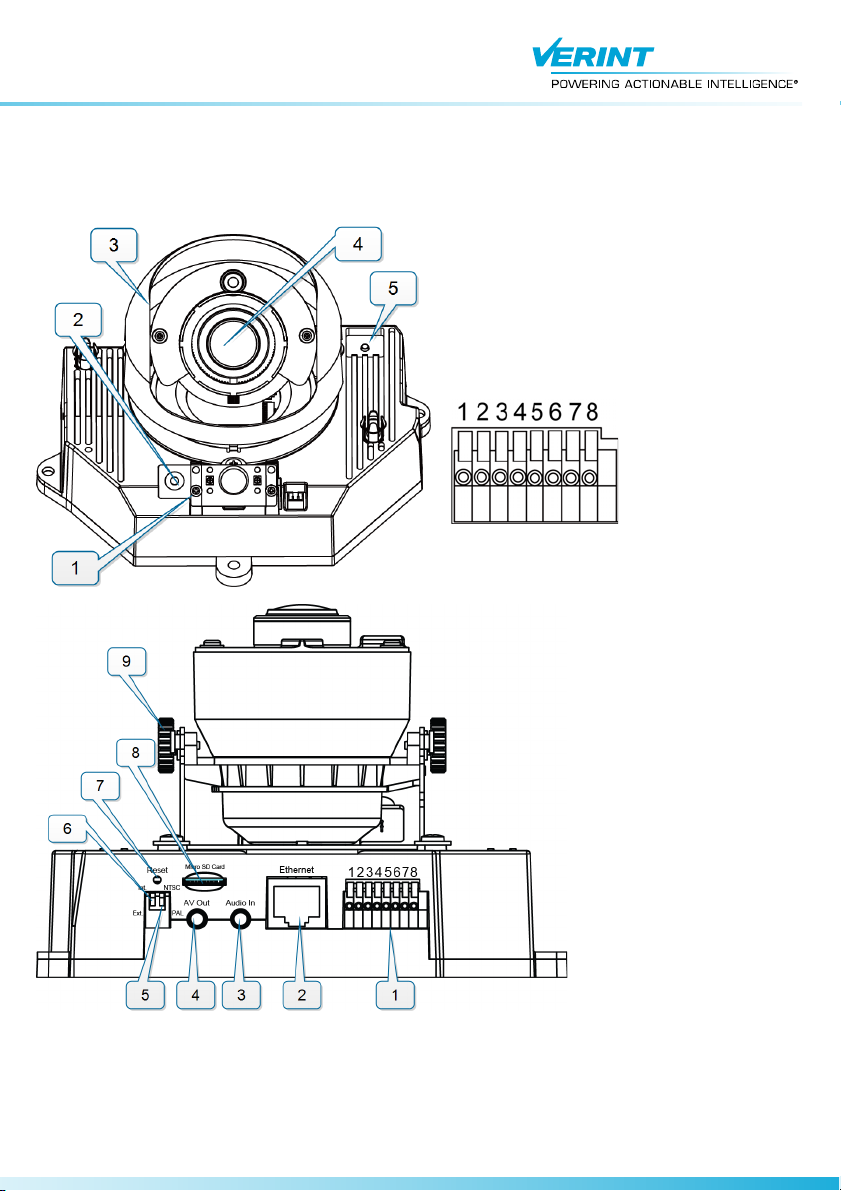
Front View Description:
1. Status LED
2. Built-in microphone
3. Lens hood
4. Lens
5. Auto Focus button
Terminal Block
Description:
1. Ground
2. 12V DC input
3. 24V AC input
4. 24V AC input
5. Ground
6. Dry contact input
Rear View Description:
1. Terminal Block
2. RJ-45 ethernet connector
3. Audio In
4. Audio/Video Out
5. NTSC/PAL switch
6. Microphone internal/external switch
7. Hardware reset button
8. Micro SD/SDHC Card slot
9. Tilt Adjustment Screw
7. Relay output
8. 12V DC output
Setting the Video Standard
The Nextiva S5100 series IP cameras can run in one of two video standards (NTSC or PAL).
► Perform the following:
1. On the back of the device move the DIP switch to NTSC or PAL.
1
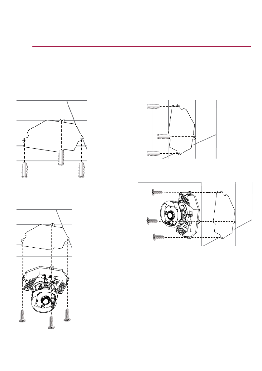
Installing the Nextiva S5100FD Models
The Nextiva S5100FD has a sophisticated 3-axis mechanism design that offers a flexible and easy hardware
installation for either ceiling or wall mount.
CAUTION: Verint will not be held liable for damages to persons or property due to the improper installation of
the Nextiva S5100 series IP cameras.
► To install on the ceiling:
1. Remove the dome cover using the supplied
screwdriver.
2. Attach the supplied alignment sticker to the wall.
3. Drill three pilot holes through the three circles on
the sticker into the wall.
4. Hammer the supplied plastic anchors into the
holes.
5. Insert the supplied three screws on each side of
the camera base.
6. Secure the camera to the ceiling with a
screwdriver.
► To install on the wall:
1. Remove the dome cover using the supplied
screwdriver.
2. Attach the supplied alignment sticker to the wall.
3. Drill three pilot holes through the three circles on
the sticker into the wall.
4. Hammer the supplied plastic anchors into the
holes.
5. Insert the supplied three screws on each side of
the camera base.
6. Secure the camera to the wall with a screwdriver.
2
 Loading...