

Verint Nextiva S4200-BZ, Nextiva S4200-AS-2V-BZ, Nextiva S4200-2V-BZ, Nextiva S4200-AS-BZ User Manual

Nextiva S4200 Series User
Guide
Covering the S4200-BZ, S4200-2V-BZ,
S4200-AS-2V-BZ, S4200-AS-BZ
Firmware Release 5.30
April 2009

© 2009 Verint Systems Inc. All Rights Reserved Worldwide.
Unauthorized use, duplication, or modification of this document in whole or in part
without the written consent of Verint Systems Inc. is strictly prohibited. By providing
this document, Verint Systems Inc. is not making any representations regarding the
correctness or completeness of its contents and reserves the right to alter this document
at any time without notice. Features listed in this document are subject to change.
Verint Systems Inc. does not warrant, guarantee or make any representation regarding
the use or the results of the use of the information, links, tools, and materials in terms
of the accuracy, reliability, quality, validity, stability, completeness, currentness, or
otherwise of its content or products. The entire risk as to the use, results and
performance of information, links, tools and materials provided or referenced herein is
assumed by the user. Verint Systems Inc. shall not be liable for damages resulting from
the use, misuse or unlawful use of the information, links, tools, and materials contained
or referenced herein.
The Verint Systems Inc. products are protected by one or more of the following U.S.,
European or International Patents: USPN 5,659,768; USPN 5,689,442; USPN 5,790,798;
USPN 6,278,978; USPN 6,370,574; USPN 6,404,857; USPN 6,510,220; USPN
6,724,887; USPN 6,751,297; USPN 6,757,361; USPN 6,782,093; USPN 6,839,667;
USPN 6,952,732; USPN 6,959,078; USPN 6,959,405; USPN 7,047,296; USPN
7,149,788; USPN 7,155,399; USPN 7,203,285; USPN 7,216,162; USPN 7,219,138;
USPN 7,254,546; USPN 7,281,173; USPN 7,284,049; USPN 7,325,190; USPN
7,466,816; USPN 7,478,051; USPN RE40,634; and other provisional rights from one or
more of the following Published US Patent Applications: US 11/394,408; US 11/771,499;
US 11/396,514; US 11/772,440; US 11/565,943; US 11/565,946; US 11/565,948;
US 11/540,739; US 11/540,086; US 11/541,313; US 11/541,252; US 11/540,282;
US 11/529,947; US 11/540,785; US 11/540,736; US 11/540,904; US 11/540,353;
US 11/608,340; US 11/608,350; US 11/608,358; US 11/567,808; US 11/692,983;
US 11/693,933; US 11/693,923; US 11/693,828; US 11/567,852; US 11/608,440;
US 12/015,621; US 11/540,322; US 11/924,201; US 11/616,490; US 11/621,134;
US 11/752,458; US 11/712,933; US 11/824,980; US 11/729,185; US 11/804,748;
US 11/831,260; US 11/395,992; US 11/359,319; US 11/359,195; US 11/359,357;
US 10/832,509; US 11/742,733; US 11/831,257; US 11/831,250; US 11/691,530;
US 11/479,267; US 11/529,942; US 11/768,349; US 11/540,281; US 10/633,357;
US 11/693,899; US 11/479,056; US 11/529,132; US 11/540,320; US 11/037,604;
US 11/529,842; US 11/540,171; US 11/478,714; US 11/529,946; US 11/868,656;
US 11/776,659; US 11/090,638; US 11/410,004; US 10/771,315; US 10/771,409;
US 11/540,900; US 11/528,267; US 12/118,781; and other U.S. and International
Patents and Patents Pending.
VERINT, the VERINT logo, ACTIONABLE INTELLIGENCE, POWERING ACTIONABLE
INTELLIGENCE, WITNESS ACTIONABLE SOLUTIONS, STAR-GATE, RELIANT, VANTAGE,
X-TRACT, NEXTIVA, ULTRA, AUDIOLOG, WITNESS, the WITNESS logo, IMPACT 360, the
IMPACT 360 logo, IMPROVE EVERYTHING, EQUALITY, CONTACTSTORE, and
CLICK2STAFF are trademarks or registered trademarks of Verint Systems Inc. or its
subsidiaries. Other trademarks mentioned are the property of their respective owners.
www.verint.com/videosolutions
Publication date: April 2, 2009
Publication revision: C

Contents
Preface ................................................................................................................ v
Chapter 1 Overview ..........................................................................................1
About the S4200 Series .....................................................................................2
Key Features ................................................................. ........................... ..2
Security .....................................................................................................3
Frame Rate and Performance ........................................................................3
Installation Kit ................... ............................ .. .. .. ........................... ... .. .. ..........6
Hardware Overview ..........................................................................................7
Hardware Dimensions and Mounting Angles .........................................................8
Chapter 2
Available Frequency Bands and Channels ...................................... .. .. .. ...............13
Wireless Cells ..................................... ............................ .. .. ...........................16
802.11 Support ..............................................................................................17
System Planning ............................................................................................18
Colocated Cells .............................................................................................. 25
RF Planning ...................................................................................................31
Chapter 3
Configuring the Wireless System ...................................................................... 35
Installing the Wireless System ......................................................................... 44
Chapter 4
Installing or Upgrading ActiveX Controls ............................................................ 56
System and RF Planning .................................................................12
2.4 GHz Band ........................................................................................... 13
4.9 GHz Band ........................................................................................... 13
5 GHz Band ..............................................................................................15
Point-to-Multipoint Application ............ ........................................................18
Using IP Cameras with the S4200 ............................................................ .. . 19
Compatibility Issues ..................................................................................21
Video Bit Rate and Data Throughput ............................................................ 22
TPC ......................................................................................................... 24
DFS ........................................................................................................ 24
Distance Limitations ......................... ............................ .. .. .. .......................25
4.9 GHz Band in the United States ..............................................................26
5 GHz Band in North America and 2.4 GHz ................................................... 27
5 GHz Band in Europe ................................................................................28
Location Evaluation ................................................................................... 31
Antenna Requirements ..............................................................................33
RF Exposure Considerations .......................................................................33
Configuring and Installing the Device .............................................34
Supplied Cables ........................................................................................35
Setting Parameters ...................................................................................36
Performing a Point-to-Point Connection ........................................................ 42
Installing the Transmitter ........................................................................... 44
Installing an External Antenna ....................................................................49
Connecting the RS-422/485 Serial Port .......................................... .............. 50
Configuring the I/Os ..................................................................................52
Using the Web Interface .................................................................55
Verint Video Intelligence Solutions iii

Contents
Viewing the Quick Status .................................................................................58
Configuring the Device ....................................................................................60
Configuring the Serial Port ..........................................................................60
Configuring Access Management .................................................................61
Viewing the System Status .........................................................................64
Configuring the Network .............................................................................65
Configuring Wireless Communication ...........................................................66
Configuring Video ......................................................................................76
Looking at Video Status ................................... .. .. ............................ .. .. .. ....82
Configuring VSIP .......................................................................................83
Configuring Audio ......................................................................................84
Configuring System Time ...........................................................................86
Configuring HTTP (Webserver) ....................................................................88
Viewing Live Video ..........................................................................................89
Configuring Live Video ...............................................................................89
Manipulating the PTZ Camera .....................................................................93
Maintaining the Device ....................................................................................94
Chapter 5
Maintaining and Troubleshooting the Device ...................................97
Updating the Firmware ....................................................................................98
Losing Connection to a Camera .........................................................................98
Finding a “Lost” S4200 ....................................................................................98
Performing a Reset .........................................................................................99
Recognizing the Status LEDs ............................................................................99
Using the Command Line Interface ............................ .. ............................ .. .. ....101
Accessing the CLI ....................................................................................102
Configuring Quality of Service ...................................................................103
Creating a Serial Connection in UDP ...........................................................103
Appendix A
Appendix B
Factory Default Configuration......................................................105
DHCP Support and APIPA ............................................................108
Appendix C Surge Protection..........................................................................110
12V/24V Power ............................................................................................111
External Antenna ..........................................................................................111
Video and Serial ...........................................................................................111
Ethernet Port .......................... .. .. .................................................................111
Appendix D
Reducing Wireless Interference ..................................................114
Interference from External Sources .................................................................115
Interference from Nextiva Devices ..................................................................115
Performing a Site Survey ..........................................................................116
Respecting Minimum Distances .................................................................120
Appendix E
Technical Specifications...............................................................123
Glossary ........................................................................................................... 126
Index ...............................................................................................................131
Compliance ......................................................................................................136
USA ............................................................................................................ 137
Canada .......................................................................................................139
Mexico ........................................................................................................141
Europe ........................................................................................................ 143
RoHS Declaration of Compliance .....................................................................145
iv Verint Video Intelligence Solutions

Preface
The Nextiva S4200 Series User Guide presents the information and procedures for
installing, configuring, and using the Nextiva® S4200 series wireless video systems.
Audience
This guide has been prepared for the following audience:
Managers
IT system administrators
Engineers
Technicians
This guide assumes that you are familiar with:
Installation and manipulation of electronic equipment
General use of computers
Local area networks (LANs) and basic IP data communication concepts and practices
Radio frequency (RF) platforms
801.11 networks if the 802.11 MAC mode is used
Web browsers
Microsoft Windows operating systems
Reference
In addition to this guide, the following documentation is also available:
Nextiva S4200 Series Installation Guide
Verint SConfigurator User Guide
Nextiva S4X00 Release Notes
A paper copy of the installation guide is included with your order.
How to Contact Us
The following Web sites and e-mail addresses provide information and support for Verint
Video Solutions and the Nextiva Intelligent Edge Device product line.
Find general information on Verint Video Solutions, including marketing material and
product information at www.verint.com/videosolutions
Download the documentation of the Intelligent Edge Devices at www.verint.com/manuals
Download firmware from the Verint Video Solutions partner extranet at
http://vvs.verint.com
Verint Video Intelligence Solutions v
.
.
.

Preface
Send your questions or comments on the current document, or any other Nextiva user
documentation, to our documentation feedback team at
documentationfeedback@verint.com.
Find contact information for the Verint Customer Service team, by phone or e-mail, or fill
out a Web request for support with a specific issues at www.verint.com/videoservice
. For
immediate assistance, contact the Customer Service team:
Location Telephone E-mail
USA and Canada 1-888-747-6246 vissupport@verint.com
Central and Latin
America
Europe, Middle East,
and Africa
Asia/Pacific
Hong Kong
Singapore
+1-631-962-9202 vissupport@verint.com
+44 (0) 845-843-7333 customersupport.emea@verint.com
+49 (0) 4321-269 81 36 mobilesupport@verint.com
(Transit applications only)
APAC_VIS_Services@verint.comp
+852 2797 5678
+65-68266099
vi Verint Video Intelligence Solutions
Overview
The S4200 series allows digital video transmission over license-free and licensed bands. It
delivers dual-stream video over local and wide area networks (LANs and WANs). Many
compression modes (also called codecs—coder/decoder) are available: a proprietary
MPEG-4-based mode called SM4, the MPEG-4 ISO 14496-2 comp liant mode, and MJPEG
(Motion JPEG). This wireless edge device is built on open standards to provide long-term
investment protection.
Combined with a Nextiva S4300 multipurpose outdoor wireless device or a commercial
802.11 access point, the S4200 series enables analog CCTV extension over the enterprise’s
network at a cost lower than that of laying new cables. The S4200 series also allows the
migration of analog CCTV cameras to an IP network.
Note: The S4200 series edge devices require professional installation.
The overview covers the following:
About the S4200 Series
Installation Kit
Hardware Overview
Hardware Dimensions and Mounting Angles
Verint Video Intelligence Solutions 1

1: Overview
About the S4200 Series
The S4200 series devices are outdoor multiband encoders/transmitters covering the
2.4GHz and 5GHz frequency bands in the 2.4GHz and 5GHz frequency bands in America
(United States, Canada, and Mexico) and Europe, and the 4.9 GHz public safety band in
America.
Key Features
The S4200 series offers many models to cover your system needs:
Device Number of
Video Inputs
S4200 1 2
S4200-2V 2 1
S4200-AS 1
S4200-AS-2V 2
1
The analytics license is not included. The analytics capabilities can be used with a Nextiva
IntelliView solution, version 5.1 or higher . Camer a tampering detection and analytics run on
the first video input of the devices. For details, refer to your Verint representative.
2
The second encoder of each input can be used for analytics or to encode video. The
second encoder gives better video encoding performances than the first one.
You can also purchase each device for the 4.9 GHz public safety band (the suffix -49 is
added to the product name, for example S4200-2V-49).
Unless otherwise specified, the word S4200 refers to any of these devices.
The S4200 offers the following additional key features:
Integration of a multiband radio, video encoder, and antenna into small outdoor rated
enclosures, for convenient, discreet, secure, and reliable installation in real-world video
security applications
Integrated antenna covering the 2.4 GHz (8.5 dBi gain), 4.9 GHz (12 dBi gain), and
5GHz (12dBi gain) bands
Video analytics capabilities on the S4200-AS and S4200-AS-2V models. In the Nextiva
IntelliView Analytics Rule Builder, the -AS models support a maximum of five active
rules and six views. For more information, refer to the documentation set of the Nextiv a
enterprise video management platform.
Camera tampering detection on the S4200-AS and S4200-AS-2V models, to
automatically monitor video images captured by a camera and provide alerts whenev er
specific characteristic of these images have changed
Number of
Video Encoders
per Input
2
2
2
2
Alarm and Audio
(with Optional
Cable)
3
33
Analytics and
Camera
Tampering
Detection
3
1
2 Verint Video Intelligence Solutions

Nextiva S4200 Series User Guide
Specific design for wireless video security applications (integrated video, bidirectional
audio, data, and I/Os)
Codec optimization for typical outdoor video surveillance scenes, to reduce the required
bit rate without impacting video quality
Wireless MAC/protocol enhancements specific to wireless video security applications
Resolution of limitations of standard WiFi technology for wireless video security
applications (hidden nodes, latency, range, and QoS)
Low-latency communication to avoid problems such as PTZ over control
12V DC or 24V AC input power
MPEG-4 ISO 14496-2 compliant and MJPEG support
RTC (Real-Time Clock) and NTP (Network Time Protocol) support
Dual encoding on the S4200, S4200-AS, and S4200-AS-2V models
Ethernet port for configuring the device or connecting an IP camera
Web interface for easy configuration and live viewing
Default serial port settings compatible with the most popular camera data port
configuration (4800 baud, 8 data bits, no parity, 1 stop bit)
Security
Every S4200 device comes with the following security features:
SSL —Every edge device comes with a unique SSL (Secure Sockets La yer) certificate for
securing its IP link. SSL is a commonly used protocol for managing the security of IP
message transmission. If enabled, the SSL protocol secures the VSIP communication
data. It does not apply to audio and video transmission.
SPCF (SmartSight Point Coordination Function)—This proprietary MAC (Media Access
Control) protocol using AES encryption (with key rotation) over the wireless link to
secure communication between the devices and resolve “hidden node,” quality of
service, range, and problems inherent to 802.11 wireless networking products. SPCF
secures VSIP communication as well as audio, video, and serial data.
Frame Rate and Performance
The available video frame rates of each encoder of the transmitter are:
NTSC—1 to 7, 10, 15, or 30 frames per second (fps)
PAL—1 to 6, 8, 12, or 25 fps
Verint Video Intelligence Solutions 3

1: Overview
On the S4200, S4200-AS, and S4200-AS-2V devices, the composite signal of a video input
is sent to two separate encoders. You can customize each encoder to meet your system
needs, for instance in terms of frame rate and resolution. Here are typical scenarios
regarding encoder use:
Scenario Encoder 1 Encoder 2
point-to-point point-to-point unused
unused point-to-point
point-to-point and web interface web viewing at rate A point-to-point at rate B
web viewing and
unused
point-to-point at rate C
video management software view at rate D record at rate E
Note: You should not use the web interface and a video management software at the
same time to avoid configuration conflicts.
The video resolutions supported by the S4200 device are:
Resolution Number of Columns Number of Lines
NTSC/PAL NTSC PAL
QCIF 176 128 144
CIF 352 240 288
2CIF 704 240 288
4CIF 704 480 576
All lines 352 480 576
2/3 D1 480 480 576
VGA 640 480 480
The following performances can be achieved using single-stream encoding. For dual
encoding values, refer to the Nextiva Intelligent Edge Devices Single-Dual Stream
Performance document, available on the extranet (Community Links > Technical Briefs >
Nextiva Intelligent Edge Devices).
Each performance value includes:
A video resolution
A frame rate expressed in frames per second (fps) using the NTSC/PAL format
4 Verint Video Intelligence Solutions

Nextiva S4200 Series User Guide
A bit rate expressed in kilobits per second (kbps)
The recommended performances for each video encoder of an S4200 and S4200-2V are:
Codec S4200 S4200-2V
Input 1 Input 2
SM4 4CIF, 30/25 fps,
3000 kbps (low to
2CIF, 30/25 fps,
2000 kbps
CIF, 30/25 fps,
800 kbps
medium motion scene)
MPEG-4 ISO 4CIF, 15/12 fps,
2000 kbps
MJPEG 4CIF, 15/12 fps,
20 kBytes
2CIF, 15/12 fps,
1500 kbps
4CIF, 15/12 fps,
20 kBytes
CIF, 30/25 fps,
800 kbps
CIF, 30/25 fps,
10 kBytes
The recommended performances for each video encoder of an S4200-AS and S4200-AS-2V
are:
Codec S4200-AS S4200-AS-2V
Input 1 Input 2
SM4 4CIF, 30/25 fps,
With analytics functionality:
4000 kbps
4CIF, 10/8 fps,
2000 kbps
CIF, 30/25 fps,
800 kbps
Without analytics functionality:
4CIF, 30/25 fps,
4000 kbps
2CIF, 30/25 fps,
2000 kbps
MPEG-4 ISO 4CIF, 30/25 fps,
With analytics functionality:
3000 kbps
2CIF, 30/25 fps,
2000 kbps
CIF, 30/25 fps,
800 kbps
Without analytics functionality:
4CIF, 30/25 fps,
4000 kbps
MJPEG 4CIF, 15/12 fps,
20 kBytes
Verint Video Intelligence Solutions 5
4CIF, 15/12 fps,
20 kBytes
2CIF, 30/25 fps,
2000 kbps
CIF, 30/25 fps,
10 kBytes

1: Overview
Installation Kit
The package contents are:
Item Description
Transmitter S4200, S4200-AS, S4200-2V, or S4200-AS-2V; includes
an integrated antenna
Mounting assembly set One set for installation on a wall or pole
Cable for video, serial port,
and power
Printed material The Nextiva S4200 Series Installation Guide
Options
High-gain antenna One external antenna; the available antennas vary
CABAA cable One cable for alarm or audio
CABET-25 cable An 82-foot (25-meter) outdoor Ethernet cable with a
CABET-50 cable A 164-foot (50-meter) outdoor Ethernet cable with a
CABPV cable A cable for video, serial port, and power
PS2440 power supply An indoor-only 24V AC power supply
Note: You must use on ly antennas certified by Verint. Doing so ensures that the combined
transmission power of the device and antenna does not exceed the maximum value
established by your country’s regulations. For more information, see page 28 and
page 136.
One cable for the S4200 and S4200-AS, two cables for the
S4200-2V and S4200-AS-2V
depending on the frequency band and the country.
weatherproof connector
weatherproof connector
6 Verint Video Intelligence Solutions
Nextiva S4200 Series User Guide
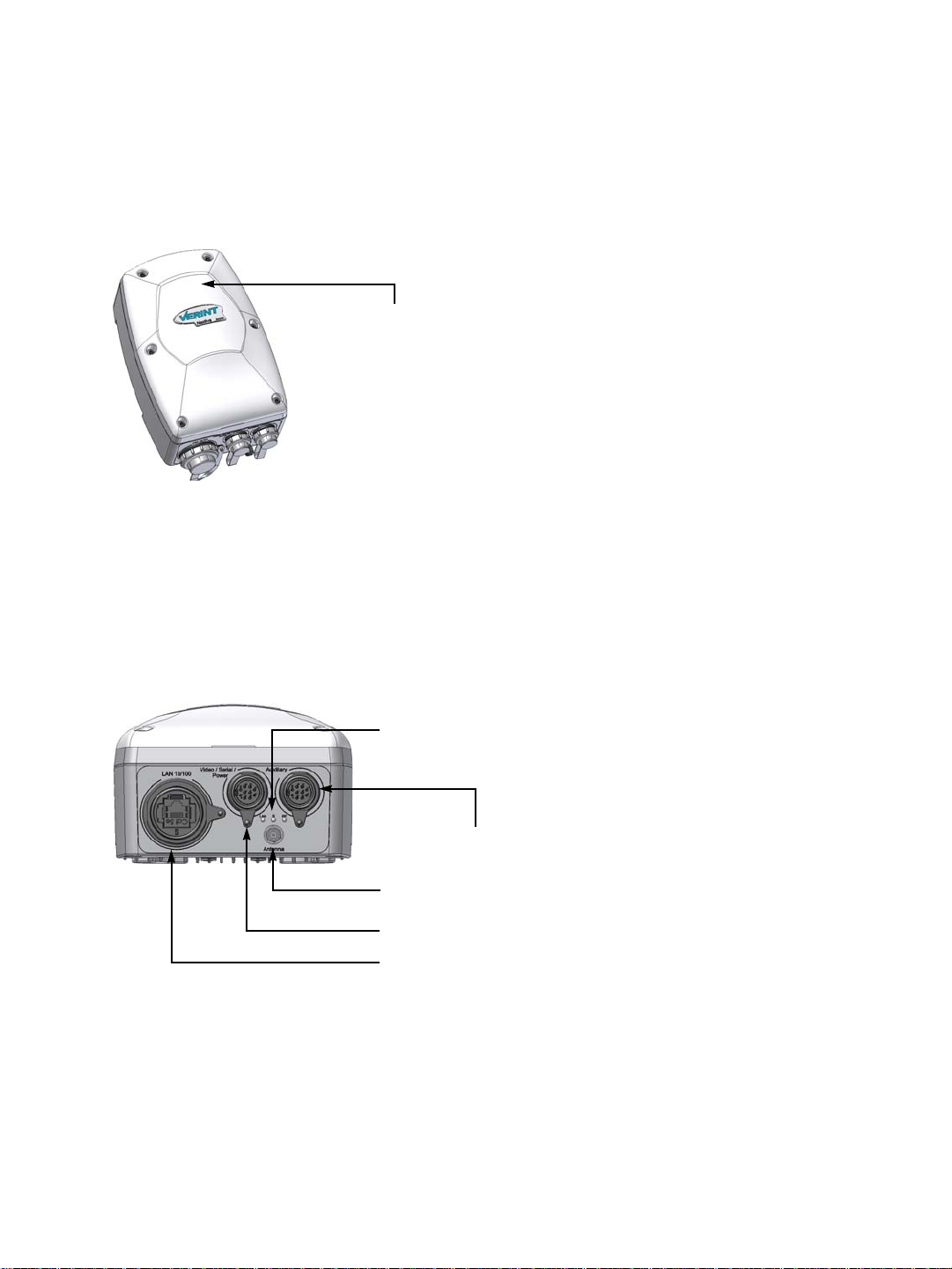
Integrated antenna
Auxiliary connector: either video 2 and serial port or
alarm and audio
Main connector for video 1, serial port, and power
Network (RJ-45) connector
LEDs
External SMA antenna connector
Hardware Overview
The S4200 electronics are enclosed in a weather-tight cast aluminum module with an
integrated wide-band antenna located in the top of the casing. All cable entries are
mounted on the underside of the module to maintain its weatherproof properties.
The underside consists of:
A network (RJ-45) connector
A main connector for video 1, serial port, and power
An auxiliary connector for video 2 and serial port (on -2V devices) or alarm and audio
(on S4200 and S4200-AS devices)
An external SMA antenna connector
Three LEDs
Verint Video Intelligence Solutions 7
1: Overview
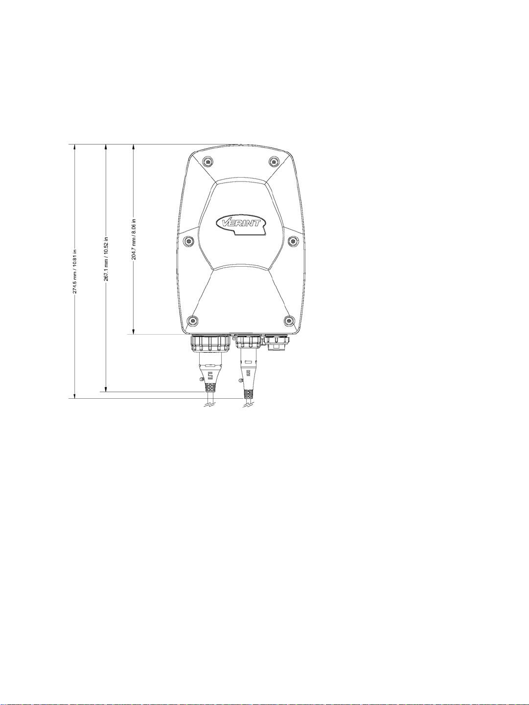
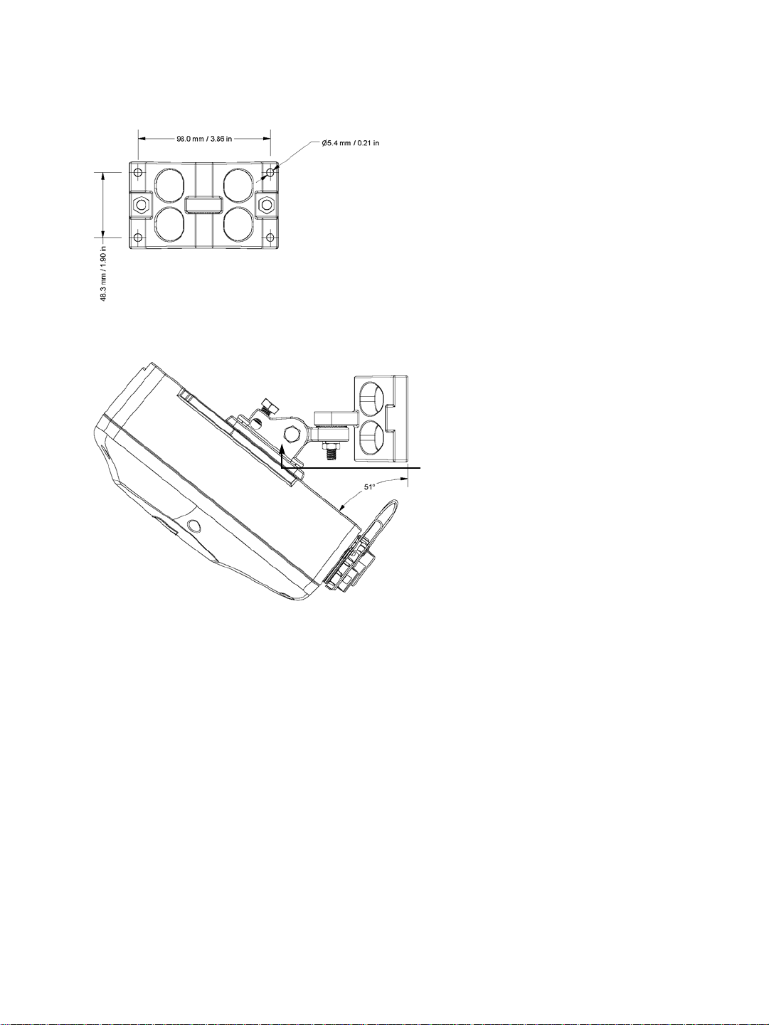
Hardware Dimensions and Mounting Angles
The top view dimensions of the S4200 are:
8 Verint Video Intelligence Solutions
Nextiva S4200 Series User Guide
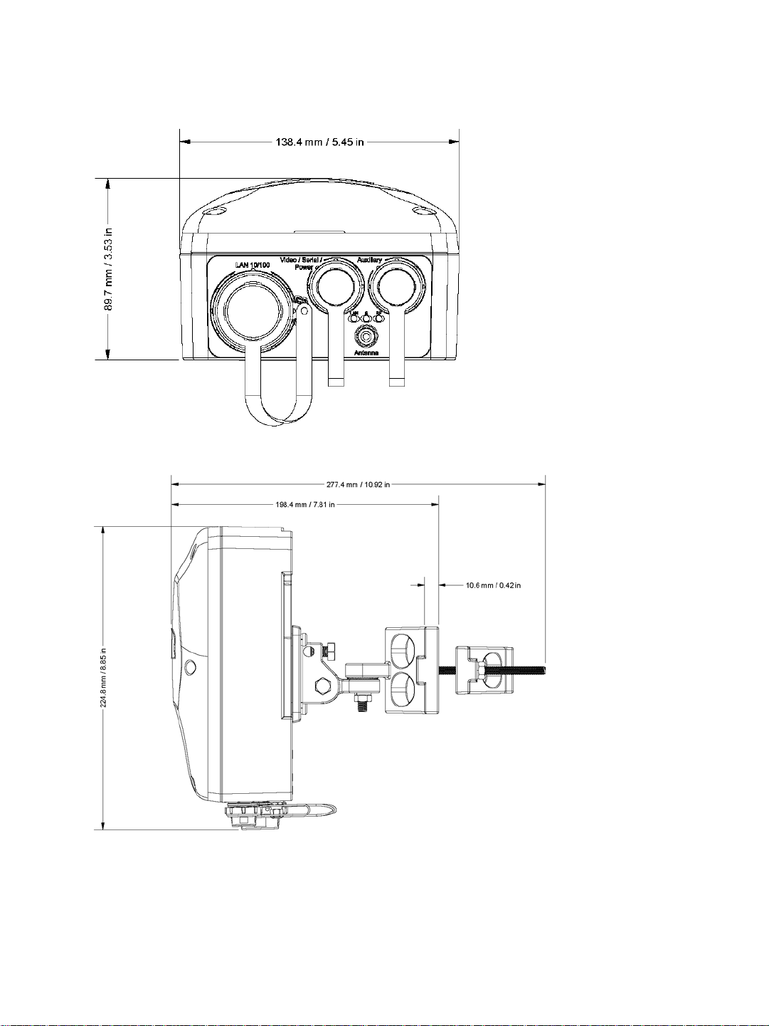
The back view dimensions are:
The side view dimensions with the mounting assembly installed are:
Verint Video Intelligence Solutions 9
1: Overview
Mounting bracket
The dimensions of the wall pivot mount are:
The maximum angular positions allowed by the mounting bracket vary depending on the
cables and the mounting structure (pipe, wall, and so on). Here is a downward tilt:
To cover more installation possibilities, you can install the mounting bracket upside down in
order to flip all the angles; for instance, to provide a downward tilt the same maximum
angle as an upward tilt. For more information about the mounting procedure, see
“Installing the Wireless System” on page 44.
10 Verint Video Intelligence Solutions
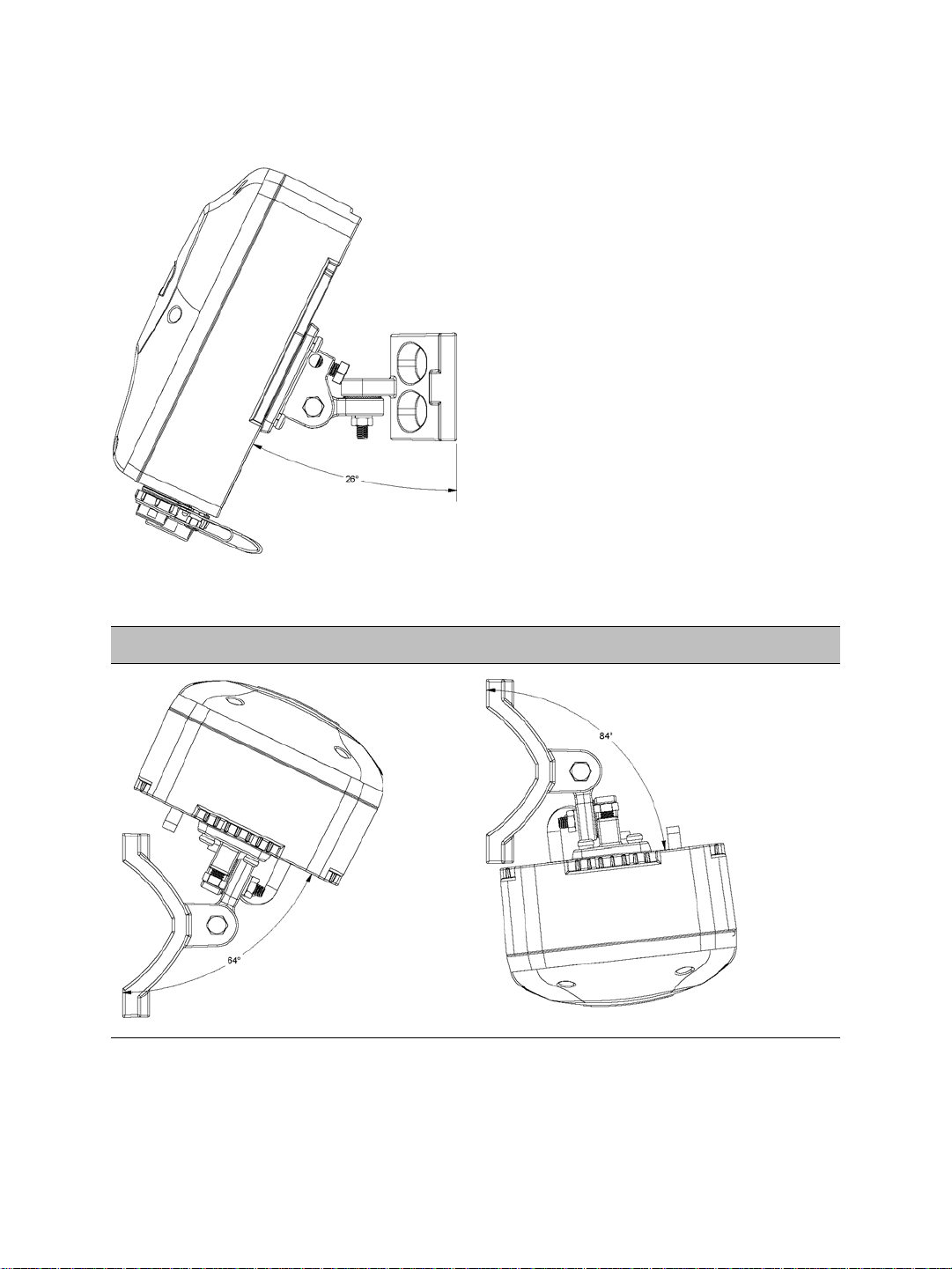
An upward tilt is:
Nextiva S4200 Series User Guide
Finally, here are rotation examples:
Left Rotation Right Rotation
Verint Video Intelligence Solutions 11

System and RF Planning
To allow optimal configuration, you must properly plan your network, especially
configuration layout and RF (radio frequency). Planni ng is especially required i f you want
to install many systems in the same area, in order to prevent radio interference
between the colocated devices and to select the appropriate antennas. In all cases, follow
the recognized RF installation practices.
To help you with your planning, you may consult the Verint Video Intelligence Solutions
extranet:
The Wireless System Margin Calculator is a tool based on an Excel spreadsheet
designed to simplify the creation of RF systems. It is located under Tools.
The Nextiva Wireless Devices Primer provides standardized information about the
design, features, and benefits of the Nextiva wireless devices. It is located under
Community Links > Technical Briefs > Nextiva Intelligent Edge Devices.
The system and RF planning tasks cover the following topics:
Available frequency bands and channels
Wireless cells
802.11 support
System planning
Colocated cells
RF planning
Verint Video Intelligence Solutions 12

Nextiva S4200 Series User Guide
Available Frequency Bands and Channels
The S4200 supports communications in the following frequency bands in America and
Europe:
2.4 GHz OFDM, also known as 802.11g
4.9 GHz OFDM, a public safety band available in the United States and Canada only
5 GHz OFDM, also known as 802.11a
To meet local regulations, you must use only antennas that conform to the requirements
specified in the “Compliance” appendix on page 136.
2.4 GHz Band
The 2.4 GHz band provides 11 channels in the United States, Canada, and Mexico, and 13
in Europe. In these two regions, only channels 1, 6, and 11 are independent (that is,
non-overlapping); in most countries, they can be used indoors or outdoors. For more
information on the availability of these channels depending on the countries, see the
“Compliance” appendix on page 136. The center frequencies of the channels are:
Channel Frequency (GHz) Channel Frequency (GHz)
1 2.412 8 2.447
2 2.417 9 2.452
3 2.422 10 2.457
4 2.427 11 2.462
5 2.432 12 2.467 (Europe only)
6 2.437 13 2.472 (Europe only)
72.442
4.9 GHz Band
The 4.9 GHz band is a licensed band for entities providing public safety services focused on
the protection of life, health, or property in the United States, Canada, and Mexico. This
band provides license holders with an interference-free, secure channel for robust and
secure broadband technologies, including wireless video surveillance systems.
Verint Video Intelligence Solutions 13

2: System and RF Planning
For more detailed information concerning the regulations governing licensing and use of
frequencies in the 4.9 GHz band:
United States—See Subpart Y of the FCC document, Memorandum Opinion and Order
and Third Report and Order at:
http://hraunfoss.fcc.gov/edocs_public/attachmatch/FCC-03-99A1.pdf
Canada—See the document SP-4940 (Spectrum Utilization Policy, Technical and
Licensing Requirements for Broadband safety in the band 4940-4990) at:
http://strategis.ic.gc.ca/epic/site/smt-gst.nsf/en/sf08667e.html
Mexico—The use of the 4.9 GHz in Mexico is subject to a special approval from
COFETEL.
The 4.9 GHz band has a width of 50 MHz (4940 to 4990 MHz). Since the standard channel
width is 20 MHz, only two independent channels can co-exist in the band. However, the
S4200 supports channel fragmentation, allowing narrower channels of 5 MHz and 10 MHz.
You can have up to four independent channels with a 10 MHz width, and up to 10 with a
5 MHz width. All these channels are for indoor or outdoor use.
The available channels are:
Channel Frequency (GHz) Channel Width
3 4.9425 5 MHz
6 4.9475 5 MHz
7 4.9525 5 MHz or 10 MHz
7 4.950 20 MHz
8 4.9575 5 MHz
9 4.9625 5 MHz or 10 MHz
10 4.9675 5 MHz
11 4.9725 5 MHz or 10 MHz
11 4.970 20 MHz
12 4.9775 5 MHz
13 4.9825 5 MHz or 10 MHz
16 4.9875 5 MHz
14 Verint Video Intelligence Solutions

Nextiva S4200 Series User Guide
5 GHz Band
In the 5 GHz band, the number of available channels and sub-bands vary depending on the
country of operation.
Most European countries adhere to the DFS (Dynamic Frequency Selection) and TPC
(Transmit Power Control) regulations established by the European Telecommunications
Standards Institute (ETSI); these regulations apply to the 5 GHz frequency band only. To
know which bands are available in your country of operation and whether your country
adheres to DFS and TPC, see the “Compliance” appendix on page 136.
In the United States and Canada, five channels are available in the 5 GHz band, all
independent and for indoor or outdoor use. The center frequencies of these channels are:
Channel Frequency (GHz)
149 5.745
153 5.765
157 5.785
161 5.805
165 5.825
In Mexico, the following channels are available, all independent and for indoor or outdoor
use:
Channel Frequency (GHz) Channel Frequency (GHz)
36 5.18 64 5.32
40 5.2 149 5.745
44 5.22 153 5.765
48 5.24 157 5.785
52 5.26 161 5.805
56 5.28 165 5.825
60 5.30
Verint Video Intelligence Solutions 15
2: System and RF Planning
S4300
S4200
In Europe, the 11 independent channels, for indoor or outdoor use, are:
Channel Frequency (GHz) Channel Frequency (GHz)
100 5.50 124 5.62
104 5.52 128 5.64
108 5.54 132 5.66
112 5.56 136 5.68
116 5.58 140 5.70
120 5.60
Wireless Cells
A wireless network is designed such that information can travel back and forth between two
points without the need for wires. For the S4200, this information consists of digitized
video, audio, and PTZ data sent to and from the wired network via an outdoor wireless
access point—either the Nextiva S4300 device or a commercial 802.11 access point.
A wireless cell consists of a group of wireless devices that communicate together on the
same frequency channel and that share the same wireless passkey. For example:
You can colocate many wireless cells if you respect certain conditions (see page 31).
Devices in a wireless cell can have two MAC (Media Access Control) roles, master or slave:
A master device controls the access over the wireless medium. It takes care of channel
selection and slave authentication to provide access to the wireless network. Finally , the
master allocates bandwidth among all connected slaves.
Slave devices need a master to access the wireless medium to transfer data, through a
polling mechanism. The S4200 devices are always slaves.
16 Verint Video Intelligence Solutions

Nextiva S4200 Series User Guide
802.11 Support
The S4200 devices can use commercial 802.11-compliant access points in all frequency
bands (2.4 GHz, 4.9 GHz, and 5 GHz).
It is assumed that the network administrators wanting to add S4200 transmitters to their
802.11 wireless network are knowledgeable about this protocol. In the remaining of this
user guide, the access point will be a Nextiva S4300.
The S4200 in the 802.11 mode supports the following security mechanisms:
No security—Not recommended
WEP—Not recommended
WPA and WPA2 (also known as 802.11i) in personal mode (PSK)
WPA and WPA2 in Enterprise mode, with an 802.1X authentication server
Note: WPA and WPA2 are not available with the proprietary SPCF MAC mode.
The supported authentication methods for WPA and WPA2 are:
Method Authentication
Means
PSK—Pre-Shared Key
(personal)
EAP-TLS (Enterprise) certificate Uses mutual authentication. The most secure
EAP-TTLS (Enterprise) login/password
PEAP (Enterprise) login/password
For more information about the TLS (Transport Layer Security) protocol, refer to RFC 2246
at http://www.ietf.org/rfc/rfc2246.txt
The supported encryption methods are:
WEP
passphrase A passphrase is required to connect to an
and certificate
and certificate
Remarks
access point and therefore access the
network.
option available.
Creates a secure TLS tunnel. Supports
MSCHAPv2 (the Microsoft version of the
Challenge Handshake Authentication protocol)
to validate logins and passwords. A certificate
is required on the server side.
Creates a secure TLS tunnel. Supports
MSCHAPv2 (the Microsoft version of the
Challenge Handshake Authentication protocol)
to validate logins and passwords. A certificate
is required on the server side.
.
AES-CCMP
Verint Video Intelligence Solutions 17
2: System and RF Planning
S4300
S4200
TKIP
Auto-select—The device automatically chooses the best available encryption scheme.
The wireless parameters associated to 802.11 differ from those of the SPCF mode. For
more information about these parameters, refer to the Verint SConfigurator User Guide.
Be aware of the following limitations in using S4200 devices in a 802.11 environment:
The S4200 will not be able to connect to an S4300.
The inherent problems with 802.11 wireless network products, such as the “hidden
node” and quality of service issues, will be present. Furthermore, the ranges of the
equipment will be lower than with the SPCF protocol.
System Planning
When installing many wireless systems in the same area, you have to carefully plan their
positions in order to prevent radio interference and select the appropriate antennas.
The grouping of devices in each wireless cell is determined by their respective locations
with respect to one another and by the available outdoor wireless access points. As a rule of
thumb, there should be a clear RF line of sight between each S4200 device and the access
point in each cell. However, the S4200 devices can be completely hidden from one another.
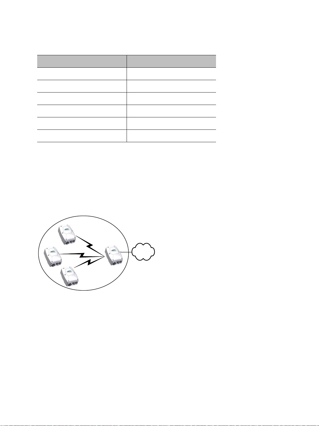
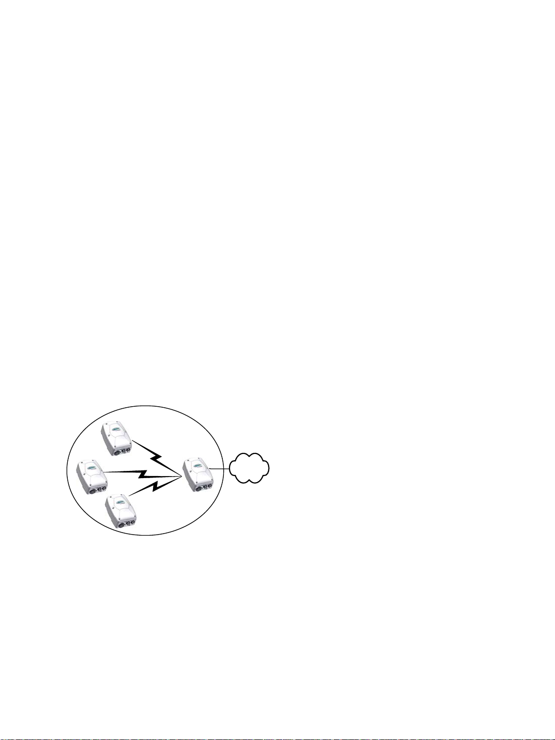
Point-to-Multipoint Application
A point-to-multipoint application is a wireless cell made up of an S4300 access point (the
master) and several S4200 transmitters (the slaves). Here is a typical point-to-multipoint
system:
For example, to associate three S4200 devices to one access point, you need to:
1. Assign the same wireless passkey to the S4200 devices and the S4300 access point.
The wireless passkey must be different from that of other colocated cells, if any.
2. Assign a frequency channel to the S4300 device. The associated S4200 devices will
automatically use their master’s channel.
3. Install the S4200 devices such that each one has a clear RF line of sight with the S4300
access point.
For the configuration and installation procedure, see page 34.
18 Verint Video Intelligence Solutions

Nextiva S4200 Series User Guide
Using IP Cameras with the S4200
The Ethernet port on the S4200 and the optional two-camera models provide new
configuration possibilities. Although video data from more than a single camera can be
transmitted from one S4200 transmitter, you must take several factors into account: the
total throughput available from the S4200, the available bandwidth for the wireless cell,
and the total amount of bandwidth used by each link in the cell.
If using a single S4200 for multiple camera transmission, it is important to remember that
the onboard processor has a finite amount of processing power available. F or instance, you
can achieve 4CIF resolution at 30 fps with a single analog camera connected to an S4200
transmitter; however, if an IP camera is connected to the Ethernet port of the S4200, some
processing power is required to transport the data stream of the IP camera from the
Ethernet port out to the radio for transmission to the S4300 access point.
The S4200 processor has the ability to forward an Ethernet stream equal to the maximum
available bandwidth on the wireless link. Obviously, using the maximum available
bandwidth only for the Ethernet port leaves no bandwidth for the video streams from the
encoders. Also, to attain good encoding performance for the analog cameras connected to
the S4200, the maximum amount of Ethernet traffic from the Ethernet port should not
exceed 2 Mbps; exceeding this value will seriously affect the performance of the encoders.
If maximum encoder performance is required (4CIF 30 fps), the total amount of Ethernet
traffic being sent from the S4200 should not exceed 4 Mbps.
For example, consider a wireless cell with four cameras using two S4200 transmitters. If
this system is designed such that the distances dictate a channel data rate of 12 Mbps, the
total amount of video bandwidth for the entire wireless cell will be 9.5 Mbps at distances of
less than 3.1 miles (5 km).
The SPCF MAC protocol divides this video bandwidth equally between the two transmitters,
therefore providing 4.75 Mbps for each pair of cameras in the wireless cell. This equates to
a total of 2.4 Mbps per camera, which can accommodate the following resolution and frame
rate (NTSC/PAL) combinations, with either two analog cameras or a combination of one
analog and one IP camera using MPEG-4 encoding:
4CIF at 15/12 fps
2CIF at 30/25 fps
CIF at 30/25 fps
As the number of multicamera links increases, the video bandwidth available for each
camera reduces. With the previous example and four transmitters instead of two, the
bandwidth available for each camera is 1.2 Mbps (9.5 Mbps divided by four transmitters
divided by two cameras per transmitter).
If an IP camera is used with MJPEG compression, you must be careful in ensuring that the
combination of frame rates and resolutions from both the IP and analog cameras do not
exceed the maximum video bandwidth available.
As link distances increase, the total available video bandwidth will decrease due to free
space loss and other attenuating factors. If this is not taken into account in the design
phase, problems will surface which will have a detrimental effect on the total system
performance.
Verint Video Intelligence Solutions 19

2: System and RF Planning
To help you plan your system, here are typical scenarios, where:
The maximum number of analog cameras is connected on the device (one for the
S4200 and two for the S4200-2V).
The compression mode is MPEG-4 or SM4.
There is a single stream per camera.
There is clear RF line of sight, with an RF margin of 15 dB or better to maintain the data
rate specified.
The video performances supplied include a video resolution, a frame rate expressed in
frames per second (fps), and bit rate expressed in kilobits per second (kbps).
The first scenario proposes a channel data rate of 6 Mbps and a maximum available video
bandwidth of 5.1 Mbps:
Analog Cameras IP Camera on S4200 IP Camera on S4200-2V
1 camera at 4CIF, 30/25 fps,
3Mbps
2 cameras at 4CIF,
1 IP camera at CIF,
30/25 fps, 1 Mbps
N/A Available bandwidth is
30/25 fps, 6 Mbps
1 camera at 4CIF, 15/12 fps,
2Mbps
2 cameras at 4CIF,
1 IP camera at CIF,
30/25 fps, 1 Mbps
N/A 1 IP camera at CIF,
15/12 fps, 4 Mbps
1 camera at 2CIF, 30/25 fps,
2Mbps
2 cameras at 2CIF,
1 IP camera at 2CIF,
30/25 fps, 2 Mbps
N/A 1 IP camera at CIF,
30/25 fps, 4 Mbps
1 camera at CIF, 30/25 fps,
1Mbps
2 cameras at CIF, 30/25 fps,
1 IP camera at 4CIF,
15/12 fps, 2 Mbps
N/A 1 IP camera at 2CIF,
2Mpbs
0 camera 1 IP camera at 4CIF,
30/25 fps, 4 Mbps
N/A
exceeded
N/A
30/25 fps, 1 Mbps
N/A
30/25 fps, 1 Mbps
N/A
30/25 fps, 2 Mbps
N/A
20 Verint Video Intelligence Solutions

Nextiva S4200 Series User Guide
The second scenario proposes a channel data rate of 54 Mbps and a maximum available
video bandwidth of 28.1 Mbps. Th ere are two transmitters in the wireless cell with exactly
the same combination of analog and IP cameras:
Analog Cameras IP Camera on S4200 IP Camera on S4200-2V
1 camera at 4CIF, 30/25 fps,
3Mbps
2 cameras at 4CIF,
30/25 fps, 6 Mbps
1 camera at 4CIF, 15/12 fps,
2Mbps
2 cameras at 4CIF,
15/12 fps, 4 Mbps
1 camera at 2CIF, 30/25 fps,
2Mbps
1 camera at CIF, 30/25 fps,
1Mbps
2 cameras at CIF, 30/25 fps,
2Mpbs
0 camera 7 IP cameras at 4CIF,
The creation and transmission of analytics metadata on the S4200-AS and S4200-AS-2V, in
conjunction with the use of an IP camera or a high bit rate Ethernet stream on the Ethernet
port, will reduce the capabilities of the video encoders. Since applications vary, you must
perform tests to determine the maximum performance of these devices when using IP
devices generating data streams in excess of 2 Mbps.
1 IP camera at CIF,
30/25 fps, 1 Mbps
N/A Not enough processing
1 IP camera at 4CIF,
15/12 fps, 2 Mbps
N/A 1 IP camera at CIF,
1 IP camera at 4CIF,
15/12 fps, 2 Mbps
1 IP camera at 4CIF,
30/25 fps, 4 Mbps
N/A 1 IP camera at 4CIF,
30/25 fps, 4 Mbps
N/A
power
N/A
30/25 fps, 1 Mbps
N/A
N/A
15/12 fps, 2 Mbps
N/A
Compatibility Issues
When planning your wireless systems, you have to take into account the firmware versions
of the involved devices. It is recommended that the S4200 transmitters have the same
firmware versions as their associated S4300 master. Furthermore, you can use the S4200
with an S3100 access point at firmware version 4.12 or higher.
In a wireless cell, the order in which you configure the devices (either the first time or later
when they are installed in the field) or update their firmware is critical if you do not want to
lose access to them. You should then:
Update the devices starting with the farthest (in terms of number of RF hops) from the
computer running the procedure.
One step at a time, get closer to the computer.
Verint Video Intelligence Solutions 21
2: System and RF Planning
S4300 3
S4300 2
S4200 2
S4200 1
S4300 1
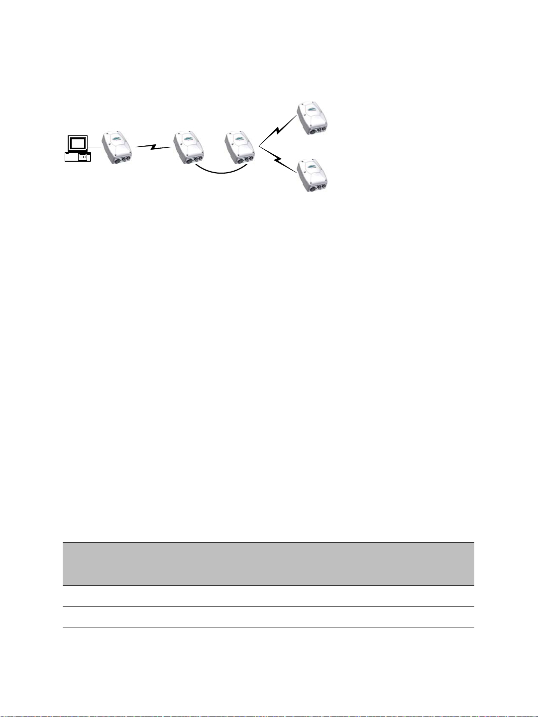
For example, consider the following setup:
You should update the devices in the following order:
1. S4200 1—You then lose contact with S4200 1.
2. S4200 2—You then lose contact with S4200 2.
3. S4300 1—You can then reach all devices.
4. S4300 2—You then lose contact will all devices except master S4300 3.
5. S4300 3—You can then reach all devices.
For the complete firmware update procedure, refer to the documentation of the Verint
software you are using.
Video Bit Rate and Data Throughput
You can theoretically connect up to 24 S4200 devices to a master access point in a wireless
cell. In practice however, video quality , frame r ate, and system lay out can limit the number
of devices that a single master access point can support.
Available video data throughput can be evaluated using the Wireless System Margin
Calculator that you can find on the Verint extranet. Available video data throughput
depends on the transmission (tx) bit rate used by each slave on the wireless network.
Video quality and frame rate influence the required data throughput. Therefore, you need
to carefully plan the number of cameras that will work on a link.
The following figures were measured in typical setup situations. They may vary depending
on your configuration. The total data throughput in a unidirectional UDP link setup varies
depending on the frequency channel width: 20 MHz in all available bands, or 5 MHz and
10 MHz in the 4.9 GHz frequency band.
The throughput for a 20 MHz channel is:
Physical Bit
Rate
6 Mbps 5.1 Mbps 5.1 Mbps 5.0 Mbps
9 Mbps 7.3 Mbps 7.3 Mbps 7.2 Mbps
Throughput for a
3-Mile (5 km)
Distance
Throughput for a
9.3-Mile (15 km)
Distance
Throughput for a
15.5-Mile (25 km)
Distance
22 Verint Video Intelligence Solutions

Nextiva S4200 Series User Guide
Physical Bit
Rate
Throughput for a
3-Mile (5 km)
Distance
Throughput for a
9.3-Mile (15 km)
Distance
Throughput for a
15.5-Mile (25 km)
Distance
12 Mbps 9.5 Mbps 9.5 Mbps 9.4 Mbps
18 Mbps 13.4 Mbps 13.3 Mbps 13.1 Mbps
24 Mbps 16.8 Mbps 16.7 Mbps 16.4 Mbps
36 Mbps 22.0 Mbps 22.0 Mbps 21.9 Mbps
48 Mbps 26.3 Mbps 25.5 Mbps 25.0 Mbps
54 Mbps 28.1 Mbps 27.1 Mbps 26.0 Mbps
The throughput for a 10 MHz channel is:
Physical Bit
Rate
Throughput for a
3-Mile (5 km)
Distance
Throughput for a
9.3-Mile (15 km)
Distance
Throughput for a
15.5-Mile (25 km)
Distance
3 Mbps 2.3 Mbps 2.3 Mbps 2.3 Mbps
4.5 Mbps 3.8 Mbps 3.7 Mbps 3.7 Mbps
6 Mbps 5.0 Mbps 4.9 Mbps 4.9 Mbps
9 Mbps 7.2 Mbps 7.1 Mbps 7.1 Mbps
12 Mbps 9.3 Mbps 9.3 Mbps 9.2 Mbps
18 Mbps 12.9 Mbps 12.8 Mbps 12.6 Mbps
24 Mbps 16.0 Mbps 15.8 Mbps 15.5 Mbps
27 Mbps 17.2 Mbps 16.9 Mbps 16.7 Mbps
The throughput for a 5 MHz channel is:
Physical Bit
Rate
Throughput for a
3-Mile (5 km)
Distance
Throughput for a
9.3-Mile (15 km)
Distance
Throughput for a
15.5-Mile (25 km)
Distance
1.5 Mbps 1.3 Mbps 1.3 Mbps 1.3 Mbps
2.25 Mbps 2.0 Mbps 2.0 Mbps 2.0 Mbps
3 Mbps 2.5 Mbps 2.5 Mbps 2.5 Mbps
4.5 Mbps 3.7 Mbps 3.6 Mbps 3.6 Mbps
Verint Video Intelligence Solutions 23

2: System and RF Planning
Physical Bit
Rate
6 Mbps 4.7 Mbps 4.6 Mbps 4.6 Mbps
9 Mbps 6.8 Mbps 6.7 Mbps 6.7 Mbps
12 Mbps 8.5 Mbps 8.5 Mbps 8.4 Mbps
13.5 Mbps 9.5 Mbps 9.4 Mbps 9.3 Mbps
The S4200 automatically adjusts the transmission speed with the current RF conditions.
Throughput for a
3-Mile (5 km)
Distance
Throughput for a
9.3-Mile (15 km)
Distance
Throughput for a
15.5-Mile (25 km)
Distance
TPC
If the country of operation of the S4200 device requires conformity to the TPC (Transmit
Power Control) rules, the maximum EIRP (effective isotropic radiated power) is reduced by
3 dBm from the allowed maximum value; for example, if the maximum EIRP is 30 dBm in
the band and region of operation, the maximum EIRP in the device will be set to 27 dBm.
The combined transmission power of the device and its antenna must not exceed this
maximum value. For that reason, you must specify the antenna gain during configuration;
the device will automatically take it into account and adjust its own transmission power
accordingly at startup. This adjustment is done in all wireless devices (masters and slaves).
To meet local regulations, you must use only antennas that conform to the requirements
specified in the “Compliance” appendix on page 136.
DFS
In countries following the DFS (Dynamic Frequency Selection) regulations, frequency
channel selection is performed by the master S4300 device. Frequency channel selection
can be automatic (default) or manual; manual selection allows a better RF planning.
Note: DFS is required only in the 5 GHz band.
The radar detection mechanism (including channel availability check and non-occupancy
period) can be performed on all wireless devices (master and slave); it also allows for
RF planning and optimal wireless network performance.
regardless of the type of frequency channel selection.
Note: To minimize the false radar detection problem in colocated systems using adjacent
frequency channels, see page 29.
You should start the master first, then power the slave when the other device is in normal
operation.
24 Verint Video Intelligence Solutions
The procedure is the same
better

Nextiva S4200 Series User Guide
1
2
3
Device initialization (3 seconds)
Roaming (2-25 seconds)
Normal operation
Radar detected?
yes
no
4
Step 2 in
master
sequence
The boot sequence of slave devices is:
1. The device goes through the standard startup procedure.
2. The device roams through the channels in the available frequency bands to locate its
master; it does not transmit any data.
3. When the master is located, the slave runs normally on the selected frequency channel.
4. If the slave detects a radar on the channel during normal operation, it informs the
master then stops operation. Upon reception of this message, the master starts its
radar detection process.
Radar detection on slave devices can be disabled; for more information, see page 29.
Colocated Cells
You can operate many wireless cells in the same location, provided you follow guidelines
relative to frequency channel, wireless passkey, and distance.
The wireless passkeys of colocated cells must be different from one another, regardless of
their frequency channels.
Distance Limitations
The distance limitations between devices in colocated cells are:
The minimum distance between two devices is 3 feet (1 meter), regardless of the band
or channel used.
To avoid material damages, you must never power any two devices while their
antennas are facing one another with a distance of less than 10 feet (3 meters).
To reduce radio interference, separate as much as possible devices sharing the same
pole or installed on the same roof, even if they do not use adjacent channels.
If using adjacent channels, see page 120 for the recommendations on the minimum
distances to respect.
Verint Video Intelligence Solutions 25

2: System and RF Planning
4.9 GHz Band in the United States
Depending on the channel width (20, 10, or 5 MHz), you can colocate 2, 4, or 10 wireless
cells respectively. For the available channels in each of the three scenarios, see page 14.
The following example presents three wireless cells with 10-MHz channels. To install such a
system, you have to:
1. In each cell, assign the same wireless passkey to the S4200 devices and the S4300
access point. The wireless passkey must be different from that of the other cells.
2. Assign a different frequency cha nnel to each S4300 device; the associated S4200
devices will automatically use their master’s channel:
Device Cell Channel Wireless Passkey
S4300_A A 7 ertynmbvcxzapoiu
S4200_A1 A 7 ertynmbvcxzapoiu
S4200_A2 A 7 ertynmbvcxzapoiu
S4200_A3 A 7 ertynmbvcxzapoiu
S4300_B B 13 PUK98rewq4123qzx
S4200_B1 B 13 PUK98rewq4123qzx
S4200_B2 B 13 PUK98rewq4123qzx
S4200_B3 B 13 PUK98rewq4123qzx
S4300_C C 11 987123jkl456wert
S4200_C1 C 11 987123jkl456wert
S4200_C2 C 11 987123jkl456wert
S4200_C3 C 11 987123jkl456wert
3. In each cell, install the S4200 devices such that each one has a clear RF line of sight
with its associated S4300 access point.
26 Verint Video Intelligence Solutions

Nextiva S4200 Series User Guide
B
A
C
S4300
S4300
S4300
This application can be illustrated this way, where the three cells are in the same location:
5 GHz Band in North America and 2.4 GHz
In the 2.4 GHz band in North America and Europe, you can use the three independent
channels (channels 1, 6, and 11) to colocate wireless cells. In the 5 GHz band, all channels
are independent.
A typical colocation example is three wireless cells. To install such a system, you have to:
1. In each cell, assign the same wireless passkey to the S4200 devices and the S4300
access point. The wireless passkey must be different from that of the other cells.
2. Assign a different frequency cha nnel to each S4300 device; the associated S4200
devices will automatically use their master’s channel. For example, in the 5 GHz band:
Device Cell Channel Wireless Passkey
S4300_A A 149 ertynmbvcxzapoiu
S4200_A1 A 149 ertynmbvcxzapoiu
S4200_A2 A 149 ertynmbvcxzapoiu
S4200_A3 A 149 ertynmbvcxzapoiu
S4300_B B 165 PUK98rewq4123qzx
S4200_B1 B 165 PUK98rewq4123qzx
S4200_B2 B 165 PUK98rewq4123qzx
Verint Video Intelligence Solutions 27

2: System and RF Planning
Device Cell Channel Wireless Passkey
S4200_B3 B 165 PUK98rewq4123qzx
S4300_C C 157 987123jkl456wert
S4200_C1 C 157 987123jkl456wert
S4200_C2 C 157 987123jkl456wert
S4200_C3 C 157 987123jkl456wert
3. In each cell, install the S4200 devices such that each one has a clear RF line of sight
with its associated S4300 access point.
An illustration of this application is on page 27, where the three cells are in the same
location.
5 GHz Band in Europe
The variety of supported colocalization setups is limited in Europe because of:
DFS regulations, mainly with the automatic channel selection that forces the master
devices to see each other.
False radar detection that can happen when using adjacent channels. By default, only
half the frequency channels are available, therefore ensuring that no adjacent channels
are used; however, you can make all channels available (for more information, see
page 29).
It is suggested to limit the number of colocated cells to six in the 5.40–5.725 GHz band. By
respecting the following steps, you can assume that the cells will not share the same
frequency channel, making the complete bandwidth available for each one:
1. Assign a different wireless passkey to each cell.
2. Ensure that all masters “see” one another. For more information, refer to the “RF
Contact between Masters” appendix in the Nextiva S4300 Series User Guide.
This step is mandatory if automatic frequency channel selection is selected, and
strongly suggested for manual selection.
3. Position the devices so that there is at least 3 feet (1 meter) between each antenna.
4. If automatic channel selection is used, set a different starting order in each master
device: 1 for the first device, 2 for the device next to it, 3 for the third one, and so on.
Installing more than six cells in the 5.40–5.725 GHz band requires the use of adjacent
channels. This situation demands greater distances between the antennas to reduce
potential radio interference and false radar detection. Therefore, you should contact the
customer service team for assistance.
28 Verint Video Intelligence Solutions

Nextiva S4200 Series User Guide
False Radar Detection
The design of wireless systems in a DFS context becomes difficult because not only can the
master devices cause an interference, but the slaves on an adjacent channel can also
generate interferences that can cause false radar detection. Therefore, to reduce the
possibility of false radar detection, it is strongly suggested to:
Limit the number of colocated cells to six.
Decrease the tx power of the wireless links that have a good RF margin (15 dB or
more). This way, the interference generated by the device is reduced.
Separate as much as possible devices sharing the same pole or installed on the same
roof.
In a context of adjacent channels, ensure that the signal level of a potentially
interfering device on the first adjacent channel does not exceed -50 dB, -36 dB on the
second channel, and -32 dB on the third channel. For example, if you use channel 100,
104 is the first adjacent channel, 108 the second channel, and 112 the third channel.
Manually select a frequency channel, to reduce the use of adjacent channels.
In addition, the following features help reduce the possibility of false detection events:
Half channel selection—This feature eliminates the possibility of using adjacent
channels. Enable this feature on all masters in a new installation to avoid the potential
conflict of having two masters on adjacent channels; in the web interface, the
parameter is called DFS/TPC Adjacent Channel Removal. By default this feature is
enabled.
If this feature is enabled, the channel list becomes:
100(DFS), 108(DFS), 116(DFS), 124(DFS), 132(DFS), 140(DFS), 254(Auto DFS/TPC)
The full channel list is:
100(DFS), 104(DFS), 108(DFS), 112(DFS), 116(DFS), 120(DFS), 124(DFS), 128(DFS),
132(DFS), 136(DFS), 140(DFS), 254(Auto DFS/TPC)
Slave radar detection management— This feature allows you to disable radar detection
on slave devices; in the web interface, the parameter is called Enable Radar Detection
on Slave. In a typical DFS environment, the slave can detect a radar and alert its
master to change the frequency channel. This situation can cause a major problem
because it increases the number of nodes that can detect false radar events caused by
adjacent channel interferences.
The default value is Disabled, meaning that the slave does not detect radars; in this
case, the slave EIRP is reduced from 30 to 23 dBm and the Tx power is automatically
reduced to meet the new maximum EIRP requirement.
Verint Video Intelligence Solutions 29

2: System and RF Planning
S4300 S4300
S4100 S4100
S4300
S4200
S4300S4300
Repeater
Master
Slave
Preferred Setups
In the 5.40–5.725 GHz band, the following colocated systems are the only ones supported
when automatic frequency channel selection is enabled, since the master devices must see
each other. In the manual channel selection mode, safe setups are:
T wo access point applications, in which the transmitters from one system do not see the
transmitters from the other cell. Both master devices see each other.
A point-to-multipoint repeater. Both master devices see each other.
30 Verint Video Intelligence Solutions

Nextiva S4200 Series User Guide
S4300
1
4
32
S4300
Risky Setup
In the 5 GHz band in Europe, the following colocated system is not supported if the
automatic frequency channel selection is enabled, or is risky with manual selection mode if
a radar is detected:
Access point applications with hidden masters. In this context, the two S4300 masters
do not see each other, while transmitters 2 and 3 do.
RF Planning
Successful operation of a wireless link depends on proper RF path planning and antenna
installation. You have to install the devices in such a way that there is a clear RF line of
sight between the two antennas. The factors to take into account are:
Location evaluation
Antenna requirements
RF exposure
Location Evaluation
The path between the two antennas must be free of obstacles that could disturb
propagation. For very short link distances—less than 500 feet (152 meters)—you may be
able to establish a working link despite partial path obstruction. However, radio waves will
be in part absorbed and in part diffracted by the obstacles, therefore affecting link
reliability. Because the reliability of such an installation is highly unpredictable, Verint does
not recommend it. A path free of any obstacle is called an RF line-of-sight path.
T o establish an RF line-of -sight path, you must take into account the sph erical nature of the
radio signal transmitted between the two antennas. This spherical signal spreads out from
both ends of the communication path and creates a three dimensional elliptical area
immediately surrounding the visual line of sight. This elliptical area varies in width
depending on the length of the line of sight; the longer the length, the thicker the elliptical
area becomes.
Verint Video Intelligence Solutions 31

2: System and RF Planning
Visual line of sight First Fresnel zone (F1)
The region outlined by this elliptical area is known as the first Fresnel zone. The Fresnel
zone is always thicker at the mid-point between the two antennas. Therefore what appears
to be a perfect line-of-sight path between the base and a remote station may not be
adequate for a radio signal; this is the difference between "visual" and "RF" line of sight.
In practice, it has been determined that a radio path can be considered an RF line-of-sight
path if it has a clear opening through 60% of the first Fresnel zone (or 0.6 F1). Here are
values for 0.6 F1 for various signal path distances and frequency bands:
Distance Values for 60% of the First Fresnel Zone Earth
Curvature
2.45 GHz 4.9 GHz 5.3 GHz 5.8 GHz
Effect
mile km ft m ft m ft m ft m ft m
1 1.6 14 4.2 9.8 3.0 9.5 2.9 8.9 2.7 0 0
4 6.5 27 8.4 19.5 5.9 18.7 5.7 18 5.5 2 0.6
7 11.3 37 11 25.8 7.9 25 7.6 23.6 7.2 6 1.8
15 24 53 16 37.8 11.5 36.4 11.1 35 10.6 29 8.8
For distances under 7 miles, the earth curvature effect is negligible. However, for greater
distances, you need to consider it in your calculations; for instance, for a 15-mile link in the
2.4 GHz band, the two antennas must be located 82 feet higher than the highest obstacle
in the RF line of sight between them (that is, 53 feet for the Fresnel zone plus 29 feet for
the earth curvature effect). Consult the customer service team for assistance.
A common problem encountered in the field and related to the 0.6 F1 clearance rule is
building obstruction. The proposed visual path may just barely clear a building but the RF
line of sight will not. In such a case, the signal will be partially absorbed and diffracted.
Increasing the height of the two antennas or the gain of the antennas are the only
alternatives to improve the link quality.
Note: At 2.4, 4.9, and 5 GHz, radio waves are highly attenuated by dense foliage. A link
established in the fall or winter season may be adversely affected in the spring and
summertime, if it is established below tree level.
32 Verint Video Intelligence Solutions

Nextiva S4200 Series User Guide
Antenna Requirements
Verint offers many antennas to meet various distance requirements. You need to consider
many factors when choosing an antenna, including the distance to cover, the RF bit rate,
the radiated power (EIRP), and the frequency band. For systems located in North America
on the 5 GHz band, you can use the Wireless System Margin Calculator located on the
Verint Video Intelligence Solutions extranet (under Tools).
You must use only antennas certified by Verint. They meet the local regulations regarding
the maximum antenna gain allowed. The certified antennas are listed in the “Compliance”
appendix on page 136.
To ensure that the device meets the maximum EIRP in the region of operation, enter the
antenna gain in the device (in the SConfigurator Wireless pane or the Wireless
Communication page of the web interface); the device will automatically take it into
account and adjust its own transmission power accordingly at startup.
For fixed point-to-point applications in the 5.725 GHz–5.850 GHz in USA and Canada,
19 dBi and 23 dBi antennas can be used without transmission power reduction. It is the
responsibility of the installer to ensure that the system is used exclusively for fixed
point-to-point operation.
Note: Connecting an antenna with a gain higher than the value for which the device is
certified for the frequency band and region of operation is prohibited. It is your
responsibility to ensure that you respect the regulations in place.
Antenna installation must be performed by certified professionals.
RF Exposure Considerations
In order to comply with the RF exposure requirements of CFR 47 part 15 in North America,
the devices must be installed in such a way as to allow a minimum separation distance of
12 inches (30 cm) between antennas and persons nearby.
Other countries may have different regulations. Please consult with local regulations prior
to installation.
Verint Video Intelligence Solutions 33

Configuring and
Installing the Device
The steps required to prepare your S4200 device for operation are:
Basic configuration
Physical installation in its final location
Alarm and audio configuration, if required
Verint Video Intelligence Solutions 34

Nextiva S4200 Series User Guide
Mating connector
Power wires
BNC video connector
RS-422/485 wires
Configuring the Wireless System
The configuration steps to execute are:
Set a series of parameters
If required, establish a point-to-point connection between the transmitter and a
receiver
Note: Prior to deployment in the field, this wireless device requires configuration and
testing.
Device configuration requires the use of the proprietary SConfigurator tool. Its late st
version is included on the Verint web site (www.verint.com/manuals
executable file (SConfigurator.exe) to the hard disk of your computer.
The minimum hardware and software requirements for the host computer needed to
configure the edge device are:
An Ethernet network card
Internet Explorer 6.0 or higher
Microsoft DirectX 8.1 or higher
). You need to copy its
Windows 2000 Service Pack 2 or higher, or Windows XP Service Pack 2 or higher
Supplied Cables
Your S4200 shipment comes with the following cables:
One or two video/serial/power cables (two cables for a -2V model)
Verint Video Intelligence Solutions 35

3: Configuring and Installing the Device
Mating connector
Alarm wires
Audio wires
One alarm/audio cable (CABAA), if the alarm and audio option was selected
Setting Parameters
Before installing a wireless system in its final location, you need to:
1. Prepare the wireless system.
2. Set network parameters.
3. Select the device name and country of operation.
4. Set wireless network parameters.
5. Check proper communication with the corresponding S4300 outdoor wireless access
point.
The first step in configuring an S4200 device is to provide a typical initial configuration of its
network parameters (including its IP address) to ensure compatibility with an existing
network.
Note: T o work properly, devices on the same network must have unique IP addresses. The
device will not prevent you from entering a duplicate address. However, its system
status LED will turn to flashing red (1-second interval); then the device will use its
default address. You then need to configure it with a proper IP address.
To prepare the wireless system:
1. In a lab, unpack the transmitter and the S4300 access point and place them on a table.
2. Write down the serial number of the device in a safe place.
3. Configure the access point for a point-to-multipoint application.
For the detailed procedure, refer to the Nextiva S4300 Installation Guide.
4. If required, connect an external antenna on the S4200; for the procedure, see page 49.
5. Plug an Ethernet cable between the network (RJ-45 ) connector of the S4200
transmitter and a computer.
6. Plug the supplied video/serial/power cable on the main connector of the S4200
transmitter.
36 Verint Video Intelligence Solutions

Nextiva S4200 Series User Guide
7. Power the device using the red and black wires of the video/serial/power cable.
Warning: To avoid material damages, you must never power any two devices while
their antennas are facing one another with a distance of less than 10 feet
(3 meters).
On an S4200-2V or S4200-AS-2V, do not use the red and black wires of the
second video/serial/power cable.
Note: CE and FCC compliance testing has been performed with the MTA572415 (CE
24V AC) and MA572416 (24V AC North America) power supplies respectively.
They correspond to the PS2440 power supply offered as an option by Verint.
Power supplies other than the approved ones require verification of operation
with the S4200 before use.
If you are using a power supply other than the one supplied by V erint, y ou need
to ensure that it has a minimum capacity of 1.6A (for 12V DC) or 25 VA (for
24V AC).
a. In 12V DC, connect each power wire of the power cable to the corresponding wire
of the power supply: the red wire to the input (+) wire and the black wire to the
ground wire (-). For more information, refer to the power supply documentation.
b. In 24V AC, connect each power wire of the supplied cable to a wire on the power
supply. Both wires are used for power.
c. Connect the electrical plug into the outlet.
To set the initial network parameters:
à
1. Start SConfigurator by double-clicking SConfigurator.exe on your hard disk. The
SConfigurator window appears.
2. In the General tab, click Program Options. The Program Options window appears.
Verint Video Intelligence Solutions 37

3: Configuring and Installing the Device
3. Check Detect All Units on LAN.
4. Ensure that the VSIP Port is 5510; otherwise, click Default.
5. Ensure that the Discovery IP Address is 255.255.255.255; otherwise, click Reset to
Broadcast.
6. Click OK.
7. Select the Units tab, then click Discover.
A device of type “Unknown” with a 169.254.X.Y IP address appears in the list; it
corresponds to your new device. This default IP address is based on the APIPA
(Automatic Private IP Addressing) addressing scheme.
X and Y are relative to the MAC
(Media Access Control) address of the device; for more information about APIPA, see
page 108.
8. Select the unknown device, then click Configure.
9. In the Reconfigure unit? confirmation window, click Yes. The New Network
Configuration window appears.
10. If you have a DHCP (Dynamic Host Configuration Protocol) server on your network,
check Use DHCP. Otherwise, enter the IP address, subnet mask, and gateway of the
device, as provided by your network administrator. For more information about DHCP,
see page 108.
11. Click OK. The device reboots with its new network configuration.
12. In the Units tab, click Discover to update the list of devices. The new S 4200 device
appears.
38 Verint Video Intelligence Solutions

Nextiva S4200 Series User Guide
13. Select the device, then click Configure.
The Unit Configuration window appears.
To set the device name and country of operation:
1. In the parameter tree of the Unit Configuration window, click Unit.
2. In the Unit Name box, assign a meaningful name to the device.
3. In the Country list, select the country of operation of the device.
You must assign the proper country of operation to the device, so that it will comply to
the DFS/TPC regulations, if applicable, respect the maximum EIRP, and use the proper
set of frequency channels.
4. In the confirmation window that appears, click Yes.
Verint Video Intelligence Solutions 39

3: Configuring and Installing the Device
To set the wireless parameters:
1. In the parameter tree, expand the Network node, then click Wireless.
2. In the Band list, select the frequency band to use.
3. If necessary in the 4.9 GHz band, change the bandwidth in the Channel Bandwidth
list.
4. In the Antenna Selection list, specify the type of antenna that will be used on the
device. Select External if you installed a high-gain antenna on the device; leave
Integrated otherwise.
5. If you are using an external antenna, enter its gain in the Antenna Gain box. If you
use the integrated antenna, check that the proper value for the selected band is
displayed; the gain is 8.5 dBi in the 2.4 GHz band and 12 dBi in the 4.9 GHz and 5 GHz
bands.
Note: Providing a gain lower than the actual gain of the antenna you are using is
prohibited.
40 Verint Video Intelligence Solutions

6. Click Set Wireless Security.
The Set Wireless Security window appears.
Nextiva S4200 Series User Guide
7. In the Format list, select the format of the passkey: Text (ASCII) or Hexadecimal.
8. In the Passkey box, enter the new passkey (case-sensitive).
The user-supplied passkey must be unique and have exactly 16 characters if the format
is Text, or 32 digits if Hexadecimal. For the wireless connection to be secure, do no
enter a known name (like a street name), but instead use a mix of digits and letters. Do
not disclose the passkey. The connection security is based on the secrecy and
uniqueness of the passkey.
9. In the Confirmation box, enter again the passkey.
10. To set the wireless passkey to its default value, click Reset.
11. Click OK.
12. In the Unit Configuration window, click OK.
13. In the Warning! window that appears, click Yes to save the new parameters.
14. In the confirmation window that appears, click OK. The device reboots with its new
wireless configuration.
15. Unplug the Ethernet cable from the S4200 device, then put back the dust cap on the
network (RJ-45) connector.
To check communication with the S4300 access point:
1. In the SConfigurator Units tab, the S4200 should be hierarchically positioned under the
S4300.
2. In the Link Status pane of the S4300, the S4200 should be in the Clients/Slaves list.
Verint Video Intelligence Solutions 41

3: Configuring and Installing the Device
Transmitter ReceiverAccess point
3. Ensure that there is end-to-end video transmission in the lab before installing the
devices in their final location.
The initial configuration is now complete for the two devices.
Performing a Point-to-Point Connection
A point-to-point connection is the association of a transmitter and a receiver to view video
coming from an analog camera on an analog monitor. The Nextiva receivers are the
S1970e-R and S1504e-R. You can connect each of these receivers to up to four
transmitters, to create a maximum of four different point-to-point connections. Here is a
single connection:
You can also use a point-to-point connection to transfer audio, input/output, or serial port
data, if the transmitter and receiver have these features.
Typically, both devices sit on the same IP subnet as SConfigurator and have the same VSIP
port; to access other devices, refer to the device discovery section in the Verint
SConfigurator User Guide.
To associate a transmitter and a receiver in a point-to-point connection:
1. Start SConfigurator.
2. In the Units tab, discover the desired devices. The discovered devices appear in the
Units box.
3. Select the Connections tab, then click Add. The Connection Creator window appears.
42 Verint Video Intelligence Solutions

Nextiva S4200 Series User Guide
4. Select a transmitter in the left column and a receiver in the right one.
In the Transmitters column, you have access to the two encoders of each input; the
video stream is the same for both. Encoder1 is always reserved for viewing live video
with the web interface, therefore you should use Encoder2 for point-to-point
connections; however, you can use the same encoder for both functions if you want the
same resolution and frame rate.
5. In the Video list, select the desired transmission mode for video data. The available
values are:
RTP/UDP—A video mode using RTP (Real Time Transport Protocol, RFC 3550) over
UDP. It is the preferred mode for LAN environments; however, it does not guarantee
proper reception of packets. (default)
VSIP/UDP—A legacy mode, using the proprietary VSIP video protocol over UDP. The
preferred UDP mode is RTP/UDP.
RTP/TCP—A video mode using RTP (Real Time Transport Protocol, RFC 3550) over
TCP. It can be useful over WANs, Internet, or LANs needing more robust or secure
connections. This mode guarantees proper reception of packets, but could slow
down the effective frame rate to a level which is not acceptable.
VSIP/TCP—A legacy mode, using the proprietary VSIP video protocol over TCP. The
preferred TCP mode is RTP/TCP.
6. If you are not transferring I/O data (typically alarms) between the two selected
devices, clear Forward I/O.
7. If you are not transferring serial port data (like PTZ commands), clear Forward Serial
Port Data.
Tip: The serial connection is automatically performed with the TCP protocol, which
may induce lag time on a slow wireless connection. If it is the case, change the
protocol to UDP. For the procedure, see page 105.
8. To enable audio between the devices, ensure that Enable Audio is checked, then select
the audio mode. The available modes are:
Full Duplex—Audio data is transferred in both directions simultaneously.
PTT/PTL—Push-to-talk/push-to-listen is a half-duplex mode that allows you to
control audio communication by using a button to switch from voice reception to
transmission mode. Audio data will be transmitted only if the PTT or PTL buttons
are pressed.
Note: On a receiver, you can activate audio on a single connection only. The active
audio connection is the last that was performed.
The audio connection will remain the same even if the S1970e-R is in guard tour
mode, that is, the receiver will not switch between the audio streams of its four
connected transmitters. For more information, refer to the Nextiva S1900e
Series User Guide.
9. Click Connect.
10. In the SConfigurator confirmation window, click OK.
Verint Video Intelligence Solutions 43

3: Configuring and Installing the Device
You should now have video on the analog monitor connected to the receiver. Audio, I/O,
and serial port data can also be transferred.
Installing the Wireless System
After successfully configuring your wireless system, you are ready to install it. To optimize
your system radio performance, carefully review the site planning information presented in
Chapter 2 on page 12. For more information about the installation procedure of your
outdoor wireless access point, refer to the Nextiva S4300 Installation Guide.
Installing a system includes:
Installing the transmitter
If required, installing an external high-gain antenna
If required, connecting the RS-422/485 serial port
Installing the Transmitter
You can install an S4200 on a wall or pole using a mounting assembly set that is included in
your shipment. The mounting assembly set includes:
A mounting bracket
A pole/wall pivot mount
A pole clamp
Two stainless steel straps
Note: You must install the mounting assembly on the S4200. It is required to properly
mount and securely ground the wireless device.
The following fasteners are also part of the set:
Item Description Scale Drawing
1 Lock washers for the pole clamp (2) and the
pole/wall mount pivot (2)
2 Lock washers for the mounting bracket (4)
3 Nuts for the pole clamp (2) and the
pole/wall mount pivot (2)
44 Verint Video Intelligence Solutions

Nextiva S4200 Series User Guide
Item Description Scale Drawing
4 Hex screws (7/16 inch) for the pole/wall
mount pivot (2)
5 Hex screws (7/16 inch) for the pole clamp
(2)
Not a scale drawing. Real length is
3.5 inches (89 mm).
6 Hex screw (0.5 inch) for the ground lug (1)
7 Screws (Phillips) for the mounting bracket
(4)
To install the mounting assembly, you need the following equipment:
Phillips #2 screwdriver
Slotted screwdriver
0.5-inch (13-mm) wrench
7/16-inch (11-mm) wrench
Four screws if the device is installed on a wall
The pole diameter can vary from 1.0 to 6.5 inches (2.55 to 16.5 cm).
Warning: When installing colocated wireless systems, you have to take into account the
distance limitations listed on page 25.
Always mount the device with the mating connectors pointing downwards.
Note: If you are not installing a high-gain antenna, position the device so that its
integrated antenna has a clear RF line of sight with the antenna of its S4300 access
point.
Verint Video Intelligence Solutions 45

3: Configuring and Installing the Device
Mounting bracket
Screw (item 7)
Lock washer (item 2)
Pole/wall pivot mount
Screw (item 4)
Screw (item 4)
Nut (item 3)
Lock washer (item 1)
Mounting hole
Mounting hole
To mount an S4200 on a pole or wall:
1. Install the mounting bracket on the rear of the device with a Phillips screwdriver, using
the four screws (item 7) and the four lock washers (item 2). The recommended torque
is 23 lbf-inch (2.6 N-m).
2. Attach the pole/wall pivot mount to the mounting bracket with a 7/16-inch (11-mm)
wrench, using the two screws (item 4), two lock washers (item 1), and two nuts
(item 3). The recommended torque is 70 lbf-inch (7.9 N-m).
3. To install the device on a w all, use four screws (not supplied) in the four mounting holes
located at the ends of the pole/wall pivot mount.
46 Verint Video Intelligence Solutions

Nextiva S4200 Series User Guide
Pole clamp
Screw (item 5)
Nut (item 3)
Lock washer (item 1)
Pole clamp
Screw (item 5)
Nut (item 3)
Lock washer (item 1)
Pole clamp
Stainless steel strap
Ground lug
Lug screw (item 6)
Cable
4. To install the device on a small pole (1–2.25 inch, or 2.55–5.7 cm diameter), position
the device and the pcole clamp the following way, then use a 7/16-inch (11-mm)
wrench to put in place the two screws (item 5) with two nuts (item 3) and two lock
washers (item 1). The recommended torque is 70 lbf-inch (7.9 N-m).
5. To install the device on a pole with a 2.25–3.25 inch diameter (5.7–8.25 cm), position
the device and the pole clamp the following way , then use a 7/16-inch (11-mm) wrench
to put in place the two screws (item 5) with two nuts (item 3) and two lock washers
(item 1). The recommended torque is 70 lbf-inch (7.9 N-m).
6. To install the device on a pole with a 4.5–6.5 inch diameter (11.4–16.5 cm), use the
supplied stainless steel straps and a slotted screwdriver.
7. Connect the device to the ground by inserting a copper cable into the ground lug, then
screw in the lug screw (item 6) using a 0.5-inch (13-mm) wrench. Use a large diameter
wire (minimum AWG 10; maximum AWG 1), and make it as short as possible. Then
ground the cable.
Verint Video Intelligence Solutions 47

3: Configuring and Installing the Device
8. Remove the dust caps from the main (Video/Serial/Power) and optionally the auxiliary
connectors.
9. Connect the video/serial/power cable to the main connector of the S4200 device. To
properly install the cable connector on the device, use your hands and turn until it
blocks. Do not use pliers.
10. Plug the BNC video connector of the video/serial/power cable on the analog camera
associated to the first input (video 1).
Note: Video analytics is only available on the first input of the device. Therefore, on
the S4200-AS-2V, you must connect the camera for which analytics is required
on the main connector of the device.
11. Perform the serial connection to the analog camera (see page 50).
12. If your device is a -2V model:
a. Connect the second video/serial/power cable to the Auxiliary connector of the
S4200 device.
b. Plug the BNC video connector of the second video/serial/power cable on the analog
camera associated to video 2.
c. Perform the serial connection to the analog camera (see page 50).
13. If you purchased the alarm/audio option, plug the supplied alarm/audio cable into the
Auxiliary connector of the device.
14. If required, install an external antenna (see page 49).
Tip: If you are installing the S4200 equipment in a lightning prone environment or in a
site where large AC mains power fluctuations are a common occurrence, add external
surge protection to secure your equipment.
Tip: For easy maintenance, it is strongly recommended to plug an outdoor Ethernet cable
on the device and to run it down the pole. Tie the cable to the pole 2 feet (0.7 meter)
or less below the device, while ensuring that there is no tension between the device
and the tie point. Insert the other end of the cable in a waterproof electrical box for
outdoor applications. Add external surge protection near the device to protect the
Ethernet port.
For more information about surge protection, see Appendix C on page 110.
Tip: If the S4200 is directly exposed to the sun in an environment likely to reach 122°F
(50°C), install a sun shield. Otherwise, reduce the maximum operating temperature
by 18°F (10°C) to protect the equipment; that is, without a sun shield, the maximum
temperature should be 104°F (40°C).
48 Verint Video Intelligence Solutions

Nextiva S4200 Series User Guide
15. To properly fuse the power supplied to the wireless device, install a fuse between the
power source and the power cable. The fuse must have the following ratings: UL Listed,
250V, 2.5A, Fast-Acting.
16. Power up the S4200 device (see page 37).
Note: Power supplies other than the approved ones (PS2440) require verification of
operation with the S4200 before use.
If you are using a power supply other than the one supplied by V erint, y ou need
to ensure that it has a minimum capacity of 1.6A (for 12V DC) or 25 VA (for
24V AC).
17. To improve the signal level between the devices, use the antenna alignment utility from
SConfigurator.
Installing an External Antenna
If you bought a high gain antenna, install it after the S4200 is in place.
Note: You can only use antennas certified by Verint. For the list, see the “Compliance”
appendix on page 136.
The antenna requires professional installation.
The installer must enter the proper antenna gain in the device so that the
transmission power is automatically adjusted. It is the responsibility of the installer
to ensure that the proper antenna gain is configured. For fixed point-to-point
applications in the 5.725 GHz–5.850 GHz in USA and Canada, 19 dBi and 23 dBi
antennas can be used without transmission power reduction. It is the responsibility
of the installer to ensure that the system is used exclusively for fixed point-to-point
operation.
An omni-directional antenna (ANT-WP8-49/5x product code) is available for installation on
a master device that requires a 360º coverage. Use it if the following conditions are met:
There is a short distance between the master and slave devices (less than
0.6 mile/1 km). A typical use is in parking lots.
At least three slaves are connected to the master.
The antennas of the slaves point towards the omni-directional antenna and are in its
vertical coverage zone (vertical beamwidth of 14º).
The omni-directional antenna is installed vertically, without any tilt.
To install an external antenna:
1. Install the antenna above the S4200 device. If you bought your antenna from Verint,
use the supplied pole mount bracket.
2. Remove the cap from the antenna connector on the S4200.
Verint Video Intelligence Solutions 49

3: Configuring and Installing the Device
3. Screw the SMA connector of the antenna cable to the antenna connector on the S4200
and tighten it with a 0.25-inch (0.6 centimeter) wrench.
Warning: Do not over-tighten to avoid damaging the connector. The recommended
torque is 8 lbf-inch (100 N-cm). You could use a calibrated SMA torque
wrench (for instance, from the Pasternack company, available at
www.pasternack.com).
Never leave the antenna connector without either the cap or the SMA
connector. The antenna connector must be terminated to avoid damaging the
device radio.
4. Apply two or three layers of electrical tape around all RF connections.
The antenna cable and connectors are weather-tight; however, vibration caused by the
wind will over time loosen the connectors and reduce the efficiency of the gaskets. The
electrical tape will prevent this situation.
5. With SConfigurator , enter the new antenna gain and change the antenna selection from
Integrated to External (see page 40).
6. Carefully align the antennas of the S4200 and access point so that they have a clear RF
line of sight.
7. To improve the signal level between both devices, use the antenna alignment utility
from SConfigurator.
Connecting the RS-422/485 Serial Port
The Nextiva edge devices support only the RS-422 and RS-485 asynchronous protocols. For
any other protoco l, you may need a converter.
On an S4200-2V transmitter, you can transmit serial data to two PTZ cameras if the
protocol is RS-485. The corresponding PTZ keyboard must be able to reference each
camera individually. In this context, perform the serial connections on both cables.
RS-422 allows you to have one PTZ camera and one fixed camera.
Use the video/serial/power cable to properly connect the device to a serial peripheral. Here
is the wiring scheme for the four-wire RS-422 or RS-485 protocol:
Cable Peripheral
Signal Name Wire Pair Wire Color Signal Name
Rx+
green/black
Rx- black RxTx+
yellow/black
Tx- black Tx-
green Rx+
yellow Tx+
50 Verint Video Intelligence Solutions

Nextiva S4200 Series User Guide
Signal ground
(brown and black)
Coax cable
BNC barrel
connector
Target device (PTZ)
Power (red and black)
Tx+ / Tx(yellow and black)
Rx+ / Rx(green and black)
Rx+ / Rx-
Signal ground
Cable Peripheral
Signal Name Wire Pair Wire Color Signal Name
Signal ground
brown Signal ground
brown/black
Signal ground black Signal ground
For example, here is an S4200 transmitter connected to a PTZ camera in an RS-422 2-wire
context:
For a two-wire, half-duplex RS-485 connection:
1. Use the following wiring scheme:
Cable Peripheral
Signal Name Wire Pair Wire Color Signal Name
Data+
green Data+
green/black
Data- black DataSignal ground
brown Signal ground
brown/black
Signal ground black Signal ground
2. Set the operating mode to RS-485 2 Wires (see page 60).
Verint Video Intelligence Solutions 51

3: Configuring and Installing the Device
Input 1 Ground Relay Relay
Alarm
Input 1
Alarm
Ground
Alarm Out+ Alarm Out-
Event sensor Event sensor
S1970e-R
S4300
S4200
Configuring the I/Os
You can progr am alarms (or events) or use the audio features of devices with a single video
input, using the supplied alarm/audio cable (CABAA).
The S4200 supports two alarm inputs, one alarm output, one audio input, and one audio
output. Each signal has a dedicated purpose:
Signal Color Purpose
Alarm Input 1 yellow/black An alarm link in a point-to-point configuration or with a
video management software
Alarm Input 2 white/black Push-to-talk (PTT) audio transmission mode
Alarm Output red/black Relay for the input 1 signal in point-to-point alarm mode
Audio Input green/black Connection to the line-out plug of a pre-amplifier
Audio Output blue/black Connection to a speaker
You cannot program PTT audio and alarms at the same time, since alarm input 1 is used in
both contexts.
Since the S4200 transmitters are mostly used with a video management software, you will
perform most configuration and activation steps in it. Otherwise, in a point-to-point
connection, use SConfigurator for setup.
Alarms
The S4200 device can generate and receive alarms. Typically, an alarm is generated on a
transmitter and acknowledged on a receiver (for instance, an S1970e-R). To generate an
alarm on an S4200 transmitter, you have to short the alarm input 1 and alarm ground pins.
The output relay on the receiver is configured to close the contact between the two alarm
output pins (up to 48V at 100 mA) upon alarm activation. For example, with an S1970e-R
receiver:
52 Verint Video Intelligence Solutions

Nextiva S4200 Series User Guide
Audio In
signal
PTT
In 2 and Gnd
signals
Audio Out
signal
Audio In
connector
Audio Out
connector
PTT
In 2 and Gnd
terminals
S1970e-R
S4300
S4200
With SConfigurator, you activate the alarm process by checking the Forward I/O box in the
Connection Creator window.
Audio
Two transmission modes for audio data are available, provided audio is supported
everywhere in your system:
Full duplex—Data is transferred in both directions simultaneously. The I/Os are
available for alarms.
PTT—The push-to-talk mode is a half-duplex mode that allows you to control audio
communication between two devices by using a button to transmit.
When creating a point-to-point connection between an S4200 transmitter and an S1970e-R
receiver in SConfigurator, you set the transmission mode in the Connection Creator window.
To activate the audio transmission channel, you must trigger an activation switch (for
example, a button) that is based on the short ing of the al arm input 2 and alarm ground
pins. If the PTT switches of both the transmitter and receiver are activated at the same
time, the receiver will have precedence: Audio will be transferred from the receiver to the
transmitter.
Here is a typical PTT application in a point-to-point context:
The S4200 device supports the line-in input type. With SConfigurator, ensure that the input
type in the Audio tab reflects this value.
Regardless of the transmission mode, the connections for the audio equipment are:
You plug the audio input signal of the device to the Line-out connector on a
pre-amplifier. Then you plug a microphone on the pre-amplifier.
You plug the audio output signal of the device to the Line-in connector on an amplifier.
Then you plug a speaker on the amplifier.
Verint Video Intelligence Solutions 53

3: Configuring and Installing the Device
The audio input/output specifications are:
Mode Gain Impedance Frequency Range
Input -20 to -3 dBV 30 kohm
300–3600 Hz
Output -45 to -3 dBV 8 ohms min.
54 Verint Video Intelligence Solutions

Using the Web Interface
In addition to SConfigurator, another tool is available to interact with the device: the web
interface. The web interface allows you to:
View a quick status of the device
Configure the device
View live video and control a PTZ camera
Perform maintenance operations
To provide this access, the S4200 must be connected to an Ethernet network or to its
access point through a wireless network.
The web interface is only available with Microsoft Internet Explorer 6.0 or later. You may
have to install or upgrade ActiveX controls when accessing the web interface for the first
time or after updating your device from a previous firmware release.
Depending on user account and security settings, you may have to provide a user name
and password when logging into the web interface or accessing it in secure mode. For more
information, see the Security parameters on page 62.
Verint Video Intelligence Solutions 55

4: Using the Web Interface
Navigation pane
Installing or Upgrading ActiveX Controls
The first time you access the web interface or after updating your device from a previous
firmware release, you need to install or upgrade the ActiveX controls for live viewing and
firmware update.
To install or upgrade the ActiveX controls:
1. Open a Microsoft Internet Explorer window.
2. Select Tools > Pop-up Blocker > Turn Off Pop-up Blocker.
3. If you upgraded the firmware of the device:
a. Select Tools > Internet Options.
b. In the Temporary Internet files box of the General tab, click Delete Files.
c. In the Delete Files window, check Delete all offline content, then click OK.
d. In the C:\Windows\Downloaded Program Files folder on your computer, delete the
SnPlayer Control and FwuEngineAx Class files.
4. In the Address box, enter the IP address of the device using the http://IP_address
format.
5. Select Tools > Internet Options > Security to lower the security level in your web
browser to enable the ActiveX components to install. Select Trusted sites, then click
Sites to add the IP address of the device in the trusted sites list.
56 Verint Video Intelligence Solutions

Nextiva S4200 Series User Guide
6. In the navigation pane, click Live Video. A yellow information bar appears below the
Address box.
7. Click the information bar.
8. In the contextual window that appears, select Install ActiveX Control.
9. If your environment is Windows XP Service Pack 2 with Internet Explorer 6, click Live
Video again in the navigation pane of the web interface.
10. In the Internet Explorer - Security Warning window, click Install.
The ActiveX is installed. You can now see live video.
11. If you do not see live video, clear the Enable YUV Support box (see page 91).
12. In the navigation pane, click Maintenance; then in the Maintenance pane, click
Update. A yellow information bar appears below the Address box.
13. Click the information bar.
14. In the contextual window that appears, select Install ActiveX Control.
15. If your environment is Windows XP Service Pack 2 with Internet Explorer 6, click
Maintenance in the navigation pane, then the Update button.
16. In the Internet Explorer - Security Warning window, click Install.
The ActiveX is installed.
17. Select Tools > Pop-up Blocker > Turn On Pop-up Blocker.
Verint Video Intelligence Solutions 57

4: Using the Web Interface
Navigation pane
Main pane
Product type
Device name IP address
Firmware version
Uptime
Viewing the Quick Status
The Quick Status pane presents a summary of the device. It is the default view when you
access the web interface. You may need to provide some of these internal parameters to
customer service specialists for troubleshooting purposes. For a more complete view of
internal parameters, look at the system status (described on page page 64).
To access the web interface:
1. Open a Microsoft Internet Explorer window.
2. In the Address box, enter the IP address of the device using the http://IP_address
format. The web interface window appears.
The web interface is composed of the following graphical elements:
Product type—The type of the device.
Device name—The descriptive name of the device. Go to page 83 to change it.
IP address—The IP address of the device.
Navigation pane—The types of information that are available in the web interface.
Main pane—The area where to configure the device, view data, and perform
maintenance tasks.
Firmware version—The current firmware version of the main processor of the
device. The latest firmware files are available on the Verint Video Intellige nc e
Solutions extranet.
58 Verint Video Intelligence Solutions

Nextiva S4200 Series User Guide
Uptime—The time since the device has been rebooted, using the following format:
x days hh:mm:ss; the “days” portion does not appear if the uptime is less than one
day. The uptime is not automatically refreshed; press F5 to update it.
To view the quick status of the device:
1. In the navigation pane, click Quick Status. Basic information appear in the main pane.
The quick status information contains:
Device Type—The type of the device. This information is also displayed on the top
banner of the web interface.
Serial Number—The serial number of the device.
Build Date—The date the firmware has been generated.
Firmware Version—The current firmware version of the device. This information is
also displayed on the bottom banner of the web interface.
Uptime—The time since the device has been rebooted. This information is also
displayed on the bottom banner of the web interface.
IP—The IP address of the device. This information is also displayed on the top
banner of the web interface.
Memory—The available internal memory in the device.
Verint Video Intelligence Solutions 59

4: Using the Web Interface
Configuring the Device
The following parameter categories are available for configuration on the device:
Serial port Wireless communication Audio
Access management Video System time
System status Video status HTTP (Webserver)
Network VSIP
Configuring the Serial Port
The device has one serial port, RS-422/485, for communicating with serial equipment (for
example, PTZ cameras). For more information about the serial port settings of the specific
product with which you want to interface, refer to its user guide or contact your product
manufacturer.
To configure the serial port:
1. In the navigation pane, expand Configuration, then click Serial Port. The serial port
parameters appear.
2. In the Bit Rate box, enter the transmission speed of the target equipment. Possible
values range from 1200 to 230,400 bits per second.
3. In the Parity list, select the parity check. Parity is used for error detection. Possible
values are Odd, Even, or None.
4. In the RS-422/485 Operating Mode list, select the way the RS-422/485 equipment
will interface with the device. Possible values are RS-422 4 Wires, RS-485 4 Wires, and
RS-485 2 Wires.
5. In the Stop Bits list, select the number of stop bits in each transmission. Possible
values are 1 or 2 bits.
60 Verint Video Intelligence Solutions

Nextiva S4200 Series User Guide
6. In the Data Bits list, select the number of bits in transmitted data. Possible values are
7 or 8 bits.
7. To continue the configuration process, select another parameter category in the
navigation pane. Otherwise, click Apply to save the changes in the device. Depending
on the changes you made, a reboot may be required; follow the on-screen instructions
in the Device Configuration Submittal pane.
Configuring Access Management
Access management takes care of user accounts and device security.
User Accounts
You can protect the configur ation of the device by restricting the access to its command line
interface (CLI) and web interface with a user name and a password. You activate user
accounts with the Use Telnet Accounts and Use Web Client Accounts parameters in the
Security page (see page 62).
Two types of users are available:
Administrator—Has all rights and is automatically available when user accounts are
activated.
Web client—Only has access to live video and quick status in the web interface. Five
web clients are available.
To configure the user accounts:
1. In the navigation pane, expand Configuration > Access Management, then click
User Accounts. The user account parameters appear.
2. In the Administrator User Name box, enter the alphanumeric string identifying the
administrator user.
3. In the Administrator Password box, enter the alphanumeric string protecting the
access to the device for the administrator user.
Verint Video Intelligence Solutions 61

4: Using the Web Interface
4. In the Web Client x User Name box, enter the alphanumeric string identifying a web
client user.
5. In the Web Client x Password box, enter the alphanumeric string protecting the
access to the device for a web client user.
6. In the Web Client x list, indicate whether the web client number x is enabled.
7. If required, repeat the web client configuration steps for all web client users. Up to five
web clients are available.
8. To continue the configuration process, select another parameter category in the
navigation pane. Otherwise, click Apply to save the changes in the device. Depending
on the changes you made, a reboot may be required; follow the on-screen instructions
in the Device Configuration Submittal pane.
Security
The security parameters are relative to the protection of the device.
To configure the security parameters:
1. In the navigation pane, expand Configuration > Access Management, then click
Security . The security parameters appear.
2. In the Telnet Session list, indicate whether the access to the CLI of the device with
Telnet is allowed.
3. In the Use Telnet Accounts list, indicate whether the use of user accounts to access
the device with the CLI is enabled. To define user accounts, see page 61.
4. In the XML Report Generation list, indicate whether the generation of an XML report
presenting the current state of the device is allowed.
5. In the IP Firmware Update list, indicate whether firmware updates on the device
through the IP network are allowed.
62 Verint Video Intelligence Solutions

Nextiva S4200 Series User Guide
6. In the HTTP Access list, indicate whether the access to the web interface of the device
in a non-secure context is allowed. If you block this access, you can only set up the
device with SConfigurator or Telnet.
7. In the HTTPS Access list, indicates whether the access to the web interface of the
device in a secure HTTP (HTTPS) context is enabled.
8. In the Use Web Client Accounts list, indicate whether the use of user accounts to
access the device with the web interface is enabled. To define user accounts, see
page 61.
9. In the Global Security Profile list, indicate whether the complete SSL security on the
device is enabled. Once this profile is activated on a device:
You cannot access it anymore with Telnet.
You cannot perform firmware updates through the IP network.
You access its web interface in a secure mode (that is, the HTTPS access mode is
enabled).
10. In the SSL Passkey box, enter a password to secure the connection with the device.
The passkey must be the same for all devices and the software tools to allow proper
secure communication between them.
Tip: You should not change this passkey with the web interface, since there could be
eavesdropping on the network. You can use SConfigurator or a video
management software to change it.
11. To continue the configuration process, select another parameter category in the
navigation pane. Otherwise, click Apply to save the changes in the device. Depending
on the changes you made, a reboot may be required; follow the on-screen instructions
in the Device Configuration Submittal pane.
Verint Video Intelligence Solutions 63

4: Using the Web Interface
Viewing the System Status
The system status information indicates the current values of internal device parameters.
These internal parameters are useful when troubleshooting the device with the assistance
of a customer service specialist.
To view the system status of the device:
1. In the navigation pane, expand Configuration, then click System Status. The system
status parameters appear.
The following information is available:
Firmware Version—The current firmware version of the main processor of the
device. The latest firmware files are available on the Verint Video Intellige nc e
Solutions extranet.
Loader Version—The version of the firmware used to load the device.
Booter Version—The version of the firmware used to boot the device.
PIC Firmware Version— The v ersion of the firmw are used in the PIC (programmable
intelligent controller) microcontroller.
Build Date—The date the firmware has been generated.
CPU Info—The version of the processing unit in the device.
CPU Frequency—The frequency (in Hz) of the processing unit in the device.
Slave CPU Frequency—The frequency (in Hz) of the slave processing unit in the
device. A value of 0 indicates that there is no slave CPU in the device.
Slave Memory Size—The size of the memory block in the slave processing unit, in
bytes. A value of 0 indicates that there is no slave CPU in the device.
64 Verint Video Intelligence Solutions

Nextiva S4200 Series User Guide
Slave CPU Count—The number of slave processing units in the device.
Uptime—The time since the device has been rebooted.
Serial Number—The serial number of the device.
CPLD Version—The version of the complex programmable logic device.
Board Version—The version of the main board in the device.
Internal Value 1—Verint technical information.
Audio Hardware—The indication of whether audio hardware is present on the
device.
Unit Tested (MM-YY)—The date the device was tested by Verint production.
Board Temperature—The temperature of the main board (in degrees Celcius).
Configuring the Network
The network parameters allow communication between the device and its IP network. For
more information about these settings, contact your network administrator.
To configure the network parameters:
1. In the navigation pane, expand Configuration, then click Network. The network
parameters appear.
2. In the DHCP Configuration list, indicate whether DHCP (Dynamic Host Configuration
Protocol) is used to automatically provide a valid network configuration for the device.
You can set this option only if the device is connected to a network that uses a DHCP
server. For more information about DHCP, see Appendix B on page 108.
3. In the Local IP Address box, enter the unique IP address of the device on the
network. The IP address is written as four numbers separated by periods; each number
is in the 0–255 range. Each device on a network must have a unique IP address.
4. In the Subnet Mask box, enter the binary configuration that specifies the subnet in
which the IP address of the device belongs. A subnet is a portion of a network that
shares a common address component. Unless otherwise specified by your network
administrator, it is recommended to use a subnet mask of 255.255.0.0.
Verint Video Intelligence Solutions 65

4: Using the Web Interface
5. In the Gateway box, enter the IP address of the network point that acts as an entrance
to another network. Never use the IP address of the device as the gateway value.
6. In the Host Name box, enter an alias for the IP address of the device, to be used by
the DNS server; this parameter is optional. It is made up of 2 to 24 alphanumerical
characters; the first one must be a character.
Note: It is up to the DHCP server to register the host name in the DNS server.
7. To continue the configuration process, select another parameter category in the
navigation pane. Otherwise, click Apply to save the changes in the device. Depending
on the changes you made, a reboot may be required; follow the on-screen instructions
in the Device Configuration Submittal pane.
Configuring Wireless Communication
The wireless communication parameters are relative to radio frequency (RF) and wireless
security . The parameters vary depending on the MAC mode (SPCF or 802.11). It is assumed
that the network administrators wanting to add S4200 transmitters to their 802.11 wireless
network are knowledgeable about this protocol; for more information on 802.11, see
page 17.
For each MAC mode, there are two sets of parameters: basic and advanced.
Basic Wireless
The S4200 contains standard wireless parameters for the SPCF and 802.11 MAC modes.
66 Verint Video Intelligence Solutions

Nextiva S4200 Series User Guide
To configure the basic wireless parameters for SPCF:
1. In the navigation pane, expand Configuration, then click Wireless Communication.
The basic wireless communication parameters appear.
2. In the MAC Mode list, select SPCF. The available media access control values are:
IEEE 802.11—The standard protocol for using commercial 802.11-compliant access
points.
SPCF—The proprietary protocol that uses AES encryption (with key rotation) over
the wireless link to secure communication between the devices and resolve “hidden
node,” quality of service, range, and problems inherent to 802.11 wireless
networking products.
SDCF—The legacy proprietary protocol not used anymore. It used AES encryption
and resolved the range and security problems of the 802.11 standard, but did not
manage the hidden node issue.
Note: A change to the MAC mode is automatically applied because it has an immediate
impact on other parameters.
3. In the Passkey box, enter a unique user-supplied, case-sensitive identifier enabling
secure and encrypted RF communication in the wireless cell. The passkey must have
exactly 16 characters or 32 hexadecimal digits.
For the wireless connection to be secure, do no enter a known name (like a street
name), but instead use a mix of digits and letters. Do not disclose the passkey. The
connection security is based on the secrecy and uniqueness of the passkey. It is good
practice to change the default passkey during the configuration process.
Verint Video Intelligence Solutions 67

4: Using the Web Interface
4. In the MAC Role list, select the function of the device in the wireless system. The
required value for an S4200 is Slave. The available values are:
Master—A device that controls the access over the wireless medium. It takes care
of channel selection and slave authentication to provide access to the wireless
medium. The master also allocates bandwidth for all connected slaves.
Slave—A device that needs a master to access the wireless medium to transfer
data. A slave can also bridge data.
Note: A change to the MAC role is automatically applied because it has an immediate
impact on other parameters. However, this change will take effect in the device
only after you save the parameter and reboot the S4200.
5. In the RF Band list, select the radio frequency band used by the device. The available
values are:
802.11a (5 GHz OFDM)
802.11g (2.4 GHz OFDM)
Public Safety (4.9 GHz OFD M)
Note: A change to the RF band is automatically applied because it has an immediate
impact on other parameters. However, this change will take effect in the device
only after you save the parameter and reboot the S4200.
6. In the Channel list, select the frequency channel, within the selected band, that the
wireless system will use. It is the master device of the S4200 that selects the channel.
However, you can specify an initial value for the roaming process by which the S4200
will find its access point; be aware that this initial channel may not be the one used by
the access point.
In a 4.9 GHz band context, the list of channels varies depending on the chosen
bandwidth.
7. In the Channel Bandwidth list, select the width of the frequency channel when the
4.9 GHz public safety band is selected. This parameter only appears for the 4.9 GHz RF
band. The values can be 5 MHz, 10 MHz, and 20 MHz (default).
Note: A change to the channel bandwidth is automatically applied because it has an
immediate impact on other parameters. However, this change will take effect in
the device only after you save the parameter and reboot the S4200.
8. In the Tx Bit Rate list, select the data rate at which the device operates. A high bit rate
reduces the effective distance between two functional devices. You can set the bit rate
in slave devices only.
When a slave connects to its master for the first time, it automatically receives the best
possible value (the Auto value), with a default RF margin set to 15 dB (to change the
margin, see page 75).
68 Verint Video Intelligence Solutions

Nextiva S4200 Series User Guide
Once the device is operating properly, Verint strongly recommends to change the
configured bit rate from Auto to the actual bit rate of the connection. This way, the
wireless communication will be more stable in the presence of changing atmospheric
conditions or other RF interferers. To know the actual bit rate of the connection, look in
the Advanced > Communication Status and Statistics > Wireless Status menu of the
CLI. If the quality of the RF link degrades severely, the actual bit rate could be lower
than the manually configured one.
The available bit rates for the S4200 device are:
Band Channel width Bit rates (Mbps)
2.4 GHz 20 MHz 6, 9, 12, 18, 24, 36, 48, and 54
4.9 GHz 5 MHz 1.5, 2.25, 3, 4.5, 6, 9, 12, and 13.5
10 MHz 3, 4.5, 6, 9, 12, 18, 24, and 27
20 MHz 6, 9, 12, 18, 24, 36, 48, and 54
5 GHz 20 MHz 6, 9, 12, 18, 24, 36, 48, and 54
9. In the Antenna Gain box, enter the gain of the antenna on the device (in dBi).
You must enter the gain if you use an external antenna with your device; with this
value, the device will be able to automatically change its transmission power so that the
total power (device and antenna) does not exceed the maximum value established by
your country’s regulations.
With the integrated antenna, you should also validate that the proper value for the
selected RF band is displayed; the gain is 8.5 dBi in the 2.4 GHz band and 12 dBi in the
4.9GHz and 5GHz bands.
Note: Providing a gain lower than the gain of the antenna used by the device is strictly
prohibited.
10. In the Antenna Selection list, select the type of antenna that will be used on the
device. The available values are:
Integrated—To use the tri-band antenna coming with the device.
External—If you installed a high gain antenna.
11. In the Country list, select the proper country of operation to the device, to comply to
the DFS/TPC regulations if applicable, to respect the maximum EIRP, and to use the
proper set of frequency channels.
12. To continue the configuration process, select another parameter category in the
navigation pane. Otherwise, click Apply to save the changes in the device. Depending
on the changes you made, a reboot may be required; follow the on-screen instructions
in the Device Configuration Submittal pane.
Verint Video Intelligence Solutions 69

4: Using the Web Interface
To configure the basic wireless parameters for 802.11:
1. In the navigation pane, expand Configuration, then click Wireless Communication.
The basic wireless communication parameters appear.
2. In the MAC Mode list, select IEEE 802.11. The available media access control values
are:
IEEE 802.11—The standard protocol for using commercial 802.11-compliant access
points.
SPCF—The proprietary protocol that uses AES encryption (with key rotation) over
the wireless link to secure communication between the devices and resolve “hidden
node,” quality of service, range, and problems inherent to 802.11 wireless
networking products.
SDCF—The legacy proprietary protocol not used anymore by the wireless devices. It
used AES encryption and resolved the range and security problems of the 802.11
standard, but did not manage the hidden node issue.
Note: A change to the MAC mode is automatically applied because it has an immediate
impact on other parameters.
70 Verint Video Intelligence Solutions

Nextiva S4200 Series User Guide
3. In the SSID (Service Set ID) box, enter the name of the wireless network; it is a
2–32 character string. It must be the same in the S4200 and in the access point.
4. In the WPA Authentication Method list, select the authentication mechanism to
grant access to the wireless data. The available values are:
WPA-PSK (Wi-Fi Protected Access version 1 in Pre-Shared Key mode, also known as
personal mode)
WPA2-PSK (WPA version 2, also known as 802.11i, in personal mode)
WPA-EAP-TLS (WPA in Enterprise mode with Extensible Authentication Protocol and
Transport Layer Security)
WPA2-EAP-TLS
WPA-EAP-TTLS (MSCHAPv2) (WPA in Enterprise mode with Extensible
Authentication Protocol, Tunneled Transport Layer Security, and the Microsoft
version of the Challenge Handshake Authentication protocol)
WPA2-EAP-TTLS (MSCHAPv2)
WPA-EAP-PEAP (MSCHAPv2) (WPA in Enterprise mode with Protected Extensible
Authentication Protocol, Transport Layer Security, and the Microsoft version of the
Challenge Handshake Authentication protocol)
WPA2-EAP-PEAP (MSCHAPv2)
None—No authentication method
The authentication method must be the same in the S4200 and in the access point.
5. In the Encryption Algorithm list, select the way wireless data is encrypted. The
available values are:
WEP (Wired Equivalent Privacy)—This encryption type is available only when the
WPA authentication method is None.
AES-CCMP (Advanced Encryption Standard-Counter Mode CBC-MAC Protocol)
TKIP (Temporal Key Integrity Protocol)
WPA-AUTO-SELECT—The encryption type is automatically chosen.
None—No encryption algorithm.
The encryption algorithm must be the same in the S4200 and in the access point.
6. In the WPA Passphrase box, enter the identifier (from 8 to 63 characters) used to
secure the RF communication between the S4200 and its access point when the
authentication method is any WPA or WPA2 flavor.
For the wireless connection to be secure, do no enter a known name (like a street
name), but instead use a mix of digits and letters. Do not disclose the passphrase. The
connection security is based on the secrecy and uniqueness of the passphrase. It is a
good practice to change the default passphrase du ring the configuration process.
The passphrase must be the same in the S4200 and in the access point.
7. In the WPA Private Key Passphrase box, enter the case-sensitive identifier (from 0
to 63 characters) used to secure the access to an 802.11 certificate.
8. In the WPA Negotiation Timeout box, enter the maximum time (in seconds) given
for the device to be authenticated.
Verint Video Intelligence Solutions 71

4: Using the Web Interface
9. In the WPA Reauthentication Period box, enter the frequency (i n days) at which the
authentication process will be re-activated with new keys, if a WPA2 authentication
method was selected.
10. In the WPA EAP Login box, enter the case-sensitive identifier (from 0 to
63 characters) used to recognize the device when a TTLS or PEAP authentication
method was selected.
11. In the WPA EAP Password box, enter the case-sensitive password (from 0 to
63 characters) used to secure the authentication process when a TTLS or PEAP method
was selected.
12. In the WEP Key box, enter the case-sensitive identifier used to secure the RF
connection when the authentication method is None. The WEP key must be the same in
the S4200 and in the access point.
13. In the RF Band list, select the radio frequency band used by the device. The available
values are:
802.11a (5 GHz OFDM)
802.11g (2.4 GHz OFDM)
Public Safety (4.9 GHz OFD M)
Note: A change to the RF band is automatically applied because it has an immediate
impact on other parameters.
14. In the Channel list, select the frequency channel, within the selected band, that the
wireless system will use. It is the master device of the S4200 that selects the channel.
However, you can specify an initial value for the roaming process by which the S4200
will find its access point; be aware that this initial channel may not be the one used by
the access point.
In a 4.9 GHz band context, the list of channels varies depending on the chosen
bandwidth.
15. In the Channel Bandwidth list, select the width of the frequency channel when the
4.9 GHz public safety band is selected. This parameter only appears for the 4.9 GHz RF
band. The values can be 5 MHz, 10 MHz, and 20 MHz (default).
Note: A change to the channel bandwidth is automatically applied because it has an
immediate impact on other parameters.
16. In the Tx Bit Rate list, select the data rate at which the device operates. A high bit rate
reduces the effective distance between two functional devices. You can set the bit rate
in slave devices only.
When a slave connects to its master for the first time, it automatically receives the best
possible value (the Auto value), with a default RF margin set to 15 dB (to change the
margin, see page 75).
72 Verint Video Intelligence Solutions

Nextiva S4200 Series User Guide
Once the device is operating properly, Verint strongly recommends to change the
configured bit rate from Auto to the actual bit rate of the connection. This way, the
wireless communication will be more stable in the presence of changing atmospheric
conditions or other RF interferers. To know the actual bit rate of the connection, look in
the Advanced > Communication Status and Statistics > Wireless Status menu of the
CLI. If the quality of the RF link degrades severely, the actual bit rate could be lower
than the manually configured one.
The available bit rates for the S4200 device are:
Band Channel width Bit rates (Mbps)
2.4 GHz 20 MHz 6, 9, 12, 18, 24, 36, 48, and 54
4.9 GHz 5 MHz 1.5, 2.25, 3, 4.5, 6, 9, 12, and 13.5
10 MHz 3, 4.5, 6, 9, 12, 18, 24, and 27
20 MHz 6, 9, 12, 18, 24, 36, 48, and 54
5 GHz 20 MHz 6, 9, 12, 18, 24, 36, 48, and 54
17. In the Antenna Gain box, enter the gain of the antenna on the device (in dBi).
You must enter the gain if you use an external antenna with your device; with this
value, the device will be able to automatically change its transmission power so that the
total power (device and antenna) does not exceed the maximum value established by
your country’s regulations.
With the integrated antenna, you should also validate that the proper value for the
selected RF band is displayed; the gain is 8.5 dBi in the 2.4 GHz band and 12 dBi in the
4.9GHz and 5GHz bands.
Note: Providing a gain lower than the gain of the antenna used by the device is strictly
prohibited.
18. In the Antenna Selection list, select the type of antenna that will be used on the
device. The available values are:
Integrated—To use the tri-band antenna coming with the device.
External—If you installed a high gain antenna.
19. In the Country list, select the proper country of operation to the device, to comply to
the DFS/TPC regulations if applicable, to respect the maximum EIRP, and to use the
proper set of frequency channels.
20. To continue the configuration process, select another parameter category in the
navigation pane. Otherwise, click Apply to save the changes in the device. Depending
on the changes you made, a reboot may be required; follow the on-screen instructions
in the Device Configuration Submittal pane.
Verint Video Intelligence Solutions 73

4: Using the Web Interface
Advanced Wireless
The advanced parameters provide more elaborate features. These parameters are the same
for all MAC modes, with the following exceptions: The Minimum Margin, Enable Radar
Detection on Slave, and DFS/TPC Adjacent Channel Removal parameters appear only for
SPCF.
To configure the advanced wireless parameters:
1. In the navigation pane, expand Configuration > Wireless Communication, then
click Advanced Wireless. The advanced wireless communication parameters appear.
If the MAC mode is SPCF, the parameters are:
If the MAC mode is 802.11, the parameters are:
2. In the Passkey Entry Format list, select the format for the wireless and WEP
passkeys. The available values are String and Hexadecimal.
74 Verint Video Intelligence Solutions

Nextiva S4200 Series User Guide
3. In the Tx Power Scale list, select the level of emitting power of the device radio. The
default level is the maximum allowed in your country for the configured antenna. If
your system operates with a comfortable RF margin (15 dB), you may reduce the
emitting power to lower the noise generated on the other RF systems located nearby.
The available values are:
Maximum—The maximum allowed.
50%—The power is reduced by 3 dB.
25%—The power is reduced by 6 dB.
12.5%—The power is reduced by 9 dB.
4. In the Sensitivity Threshold list, select the minimum signal level perceived by the
radio of the device. Reducing the sensitivity of the radio enables unwanted “noise” to be
filtered out. A safe value is 10 dB below the current received signal level (displayed in
the CLI in the Advanced > Communication Status and Statistics > Wireless Status
menu). The default value, Normal, represents the most sensitive context. You must be
careful not to reduce the sensitivity to a level where the device would not “hear” its
legitimate correspondent. The other available values are -80 dBm, -75 dBm, -70 dBm,
and -60 dBm.
5. In the Minimum Margin box, enter the difference in dB between the actual signal
received by the device and the minimum signal required by a given bit rate to correctly
receive data on the RF link. The default minimum margin is 15 dB. This parameter is
used when the transmission bit rate is set to Auto. It only appears if the MAC mode is
SPCF.
6. In the Enable Radar Detection on Slave list, indicate whether radar detection is
enabled on slave devices in a DFS context; this parameter only appears if the selected
RF band supports DFS and if the MAC mode is SPCF. For more information on radar
detection, see page 29.
7. In the Number of Frames per Burst box, enter the maximum number of data frames
that are sent on the wireless network by a slave device each time its master polls it.
The value range is 1–8. Default is 8. The performance of the wireless network increases
as the number of frames increases.
Typically this value is set on a slave device to configure its connection to its master.
Setting this value on the master limits the maximum number of frames for all slaves
connected to it. If a slave has a lower limit than the value provided by the master, the
lowest limit will be taken.
8. In the Maximum Polling Latency box, enter the maximum delay between two polls
for the same slave, in milliseconds. The value range is 10–255. Default is 255: It
indicates that there is no latency control and provides the maximum performances.
SPCF is a polling protocol. Each slave is polled one after the other. The polling latency
is the time taken to poll all the connected slaves. For delay sensitive applications like
PTZ, it can be useful to have control on this delay. When enabled, polling latency
control will automatically adjust the maximum number of frames per burst for each
slave so that the maximum latency delay is respected. However, doing so reduces the
maximum performances of the wireless network.
9. In the IP Multicast Forward from this Interface list, indicate whether multicast
data coming from the wireless network is allowed to be sent to the Ethernet network.
Verint Video Intelligence Solutions 75

4: Using the Web Interface
10. In the Indoor/Outdoor RF Regulation list, select the regulation regarding the
location of the device; the location depends on the country of operation and frequency
band. The available values are Indoor, Outdoor, or Indoor/Outdoor. The available
frequency channels are different for each location regulation. The default factory value
for most countries is Indoor/Outdoor.
Under the RF regulation, a device programmed to be used only indoors must not be
installed outdoors, and vice versa.
To know which frequency channels are available in your country of operation in each of
the three operation modes, see the “Compliance” appendix on page 136.
11. In the DFS/TPC Adjacent Channel Removal list, indicate whether the available list
of frequency channels is reduced to avoid the use of adjacent channels. For more
information, see page 29. This parameter only appears if the MAC mode is SPCF.
12. To continue the configuration process, select another parameter category in the
navigation pane. Otherwise, click Apply to save the changes in the device. Depending
on the changes you made, a reboot may be required; follow the on-screen instructions
in the Device Configuration Submittal pane.
Configuring Video
The following aspects of the video functions of the device are available for configuration:
General parameters
Encoder
Depending on the model, you have access to one or two (on the -2V models) video inputs.
76 Verint Video Intelligence Solutions

Nextiva S4200 Series User Guide
General Parameters
Some parameters are common to all video functions of each input of the transmitter.
To configure the general video parameters of the device:
1. In the navigation pane, expand Configuration > Advanced, then click Video. On an
S4200-2V or S4200-AS-2V, expand Video, then click the desired Video Input.
2. In the Video Standard list, select the analog display standard. Possible values are:
NTSC—Used in North America, Central America, a number of South American
countries, and some Asian countries, including Japan.
PAL—Used in United Kingdom, much of western Europe, several South American
countries, some Middle East and Asian countries, several African countries,
Australia, New Zealand, and other Pacific island countries.
3. In the Brightness box, enter the total amount of light in a color.
4. In the Contrast box, enter the range of colors in the image.
5. In the Saturation box, enter the intensity of the colors in the image.
6. In the Hue box, enter the relative amounts of red, green, and blue in a color.
7. To continue the configuration process, select another parameter category in the
navigation pane. Otherwise, click Apply to save the changes in the device. Depending
on the changes you made, a reboot may be required; follow the on-screen instructions
in the Device Configuration Submittal pane.
Encoder
The video parameters are the same for the two encoders of each video input in the device.
However, they vary depending on the compression mode: There is one set of parameters
for the SM4 and MPEG4 Compliant Simple Profile modes, and another one for MJPEG.
Verint Video Intelligence Solutions 77

4: Using the Web Interface
Compression
mode
To configure the encoder parameters for the SM4 or MPEG4 Compliant Simple
Profile compression mode:
1. In the navigation pane, expand Configuration > Advanced > Video, then click the
desired Encoder. On an S4200-2V or S4200-AS-2V, expand the desired Video Input
before clicking an Encoder.
2. In the Compression Mode box, select SM4 or MPEG4 Compliant Simple Profile. The
compression mode represents the way the video is compressed. The following codecs
(coders/decoders) are available:
SM4—The proprietary MPEG-4-based mode.
MPEG4 Compliant Simple Profile—The MPEG-4 ISO 14496-2 compliant mode.
MJPEG—The Motion JPEG mode that uses standard JPEG still images.
3. If the previous compression mode was MJPEG, click Apply to save the changes and see
the SM4 or MPEG4 Compliant Simple Profile parameters.
The SM4 or MPEG4 Compliant Simple Profile parameters appear.
4. In the Target Bit Rate box, enter the maximum number of kilobits per second that
you want the device to generate. V alid target bit rates r ange from 9 to 6000 kilobits per
second.
5. In the Target Frame Rate box, enter the maximum number of frames per second
(fps) that will be encoded and transferred by the transmitter. This parameter can be set
to 1 to 7, 10, 15, or 30 fps in NTSC mode and 1 to 6, 8, 12, or 25 fps in PAL mode.
78 Verint Video Intelligence Solutions

Nextiva S4200 Series User Guide
6. In the Minimum Quantizer box, enter the high video quality boundary. The lower the
value, the higher the video quality and the file size. The value range is from 2 to 31.
7. In the Maximum Quantizer box, enter the low video quality boundary. A higher
quantizer value means less video quality but a smaller file size. The value range is from
2 to 31.
8. In the Input Filter Mode list, select the level of filtering applied to the video signal
before it is encoded, helping to remove high frequency noise from lower quality
cameras or noisy video feeds. The available values are Low, Medium, High, or None.
9. In the Noise Reduction Filter Mode list, select the filtering of small variations in
pixels in otherwise motionless sections of the video, to be used in all conditions to
reduce the bit rate. Using this filter also helps reduce the number of false alarms in low
light conditions. The available values are Low (default), Medium, High, and None.
10. In the Resolution list, select the measure of how clear and crisp the video image
appears. Each resolution corresponds to a specific number of pixels (columns * lines)
for each picture of the video sequence. The available resolutions are: QCIF, CIF, 2CIF,
4CIF, All lines, 2/3 D1, and VGA.
11. In the Rate Control Mode list, select the mode controlling the bit rate variation. The
available modes are:
CFR (Constant Frame Rate)—This mode maintains the target frame rate. Video
quality may suffer and the bit rate may exceed the target value.
CBR (Constant Bitrate)—This mode is the most effective to maintain the target bit
rate. Video quality may suffer (frames may be skippe d) and the frame rate may
decrease. This mode should be used when transmitting video over networks that
have very limited bandwidths, and with an intra-interval value of 0.
CSR (Constant Storage Rate)—This is the optimized mode, based on CBR, to be
used for the Nextiva enterprise video management software to make good use of
the storage capacity.
12. In the Web Multicast IP Address box, enter the IP address of the multicast group
from which the web interface will get live video, if the web streaming method is
Multicast UDP (see page 88). This parameter applies to Input 1/Encoder 1 only.
13. In the Web Multicast IP Port box, enter the IP port of the multicast group from which
the web interface will get live video, if the web streaming method is Multicast UDP (see
page 88). This parameter applies to Input 1/Encoder 1 only.
14. In the Intra Interval box, enter the frequency at which a complete video frame (called
I-frame) is sent by the encoder. The available values are in the 0–1000 range. A value
of X means that a complete image refresh will occur every X frames.
Tip: It is not recommended to use a value of 0.
15. In the Frame Format list, select the way the video fields are compressed. The
available values are:
Field over Field—The proprietary mode used by the Nextiva edge devices.
Interlaced Frame—The MPEG-4 compliant mode where the two video fields are
interlaced.
Verint Video Intelligence Solutions 79

4: Using the Web Interface
Deinterlaced Frame—The MPEG-4 compliant mode where the two video fields are
converted to a progressive scan image by a deinterlacing filter. This filter removes
interlaced artifacts for playback on a progressive scan monitor.
16. To continue the configuration process, select another parameter category in the
navigation pane. Otherwise, click Apply to save the changes in the device. Depending
on the changes you made, a reboot may be required; follow the on-screen instructions
in the Device Configuration Submittal pane.
To configure the encoder parameters for the MJPEG compression mode:
1. In the navigation pane, expand Configuration > Advanced > Video, then click the
desired Encoder. On an S4200-2V or S4200-AS-2V, expand the desired Video Input
before clicking an Encoder.
2. In the Compression Mode box, select MJPEG. The compression mode represents the
way the video is compressed. The following codecs (coders/decoders) are available:
SM4—The proprietary MPEG-4-based mode.
MPEG4 Compliant Simple Profile—The MPEG-4 ISO 14496-2 compliant mode.
MJPEG—The Motion JPEG mode that uses standard JPEG still images.
3. Click Apply to save the changes and see the MJPEG parameters.
The MJPEG parameters appear.
4. In the Target Frame Rate box, enter the maximum number of frames per second
(fps) that will be encoded and transferred by the transmitter. This parameter can be set
to 1 to 7, 10, 15, or 30 fps in NTSC mode and 1 to 6, 8, 12, or 25 fps in PAL mode.
5. In the Input Filter Mode list, select the level of filtering applied to the video signal
before it is encoded, helping to remove high frequency noise from lower quality
cameras or noisy video feeds. The available values are Low, Medium, High, or None.
80 Verint Video Intelligence Solutions

Nextiva S4200 Series User Guide
6. In the Noise Reduction Filter Mode list, select the filtering of small variations in
pixels in otherwise motionless sections of the video, to be used in all conditions to
reduce the bit rate. Using this filter also helps reduce the number of false alarms in low
light conditions. The available values are Low (default), Medium, High, and None.
7. In the Resolution list, select the measure of how clear and crisp the video image
appears. Each resolution corresponds to a specific number of pixels (columns * lines)
for each picture of the video sequence. The available resolutions are: QCIF, CIF, 2CIF,
4CIF, All lines, 2/3 D1, and VGA.
8. In the Web Multicast IP Address box, enter the IP address of the multicast group
from which the web interface will get live video, if the web streaming method is
Multicast UDP (see page 88). This parameter applies to Input 1/Encoder 1 only.
9. In the Web Multicast IP Port box, enter the IP port of the multicast group from which
the web interface will get live video, if the web streaming method is Multicast UDP (see
page 88). This parameter applies to Input 1/Encoder 1 only.
10. In the Frame Format list, select the way the video fields are compressed. The
available values are:
Field over Field—The proprietary mode used by the Nextiva edge devices.
Interlaced Frame—The MPEG-4 compliant mode where the two video fields are
interlaced.
Deinterlaced Frame—The MPEG-4 compliant mode where the two video fields are
converted to a progressive scan image by a deinterlacing filter. This filter removes
interlaced artifacts for playback on a progressive scan monitor.
11. In the Rate Control Mode list, select the mode controlling the file size variation. The
available modes are:
CFS (Constant File Size)—The quality of the images may vary, but their size will be
targeted to the value specified by the Target File Size parameter.
VFS (Variable File Size)—The quality of the image is set by the Variable File Size
Quality parameter, but the size of the image will vary, depending of the encoded
image.
12. In the Target File Size box, enter the target size of each image that will be encoded
(in Kbytes), if the rate control mode is CFS. The available values are in the 1–100
range.
13. In the Variable File Size Quality list, select the quality of the encoded images, if the
rate control mode is VFS. The value range is from VFS1 (high quality) to VFS7 (worst
quality).
14. To continue the configuration process, select another parameter category in the
navigation pane. Otherwise, click Apply to save the changes in the device. Depending
on the changes you made, a reboot may be required; follow the on-screen instructions
in the Device Configuration Submittal pane.
Verint Video Intelligence Solutions 81

4: Using the Web Interface
Looking at Video Status
The video status presents the current values of video characteristics for each video
encoder. These internal parameters are useful when troubleshooting the device with the
assistance of a customer service specialist.
To see the video status of the device:
1. In the navigation pane, expand Configuration > Advanced > Video Status, then
click the desired encoder. The video status parameters appear.
The available information is:
Current Frame Rate—The current frame rate of the encoder, in frames per second.
Current Bit Rate—The current number of kilobits per second generated by the
encoder.
Current Quantizer—The current quantizer used by the encoder, multiplied by 100.
Average Frame Rate— The av erage fr ame r ate in the encoder, in frames per second.
It is based on a 2-minute moving average.
Average Bit Rate—The average number of kilobits per second generated by the
encoder. It is based on a 2-minute moving average.
Average Quantizer—The average quantizer, multiplied by 100. It is based on a
2-minute moving average.
Video Input Locked—The indication of whether the input signal is locked.
Video Decoder AGC Value—The automatic gain control value of the video
analog-to-digital converter.
82 Verint Video Intelligence Solutions

Nextiva S4200 Series User Guide
Configuring VSIP
Parameters are available to configure the VSIP proprietary communication protocol.
To configure the VSIP parameters:
1. In the navigation pane, expand Configuration > Advanced, then click VSIP. The
VSIP parameters appear.
2. In the VSIP Port box, enter the communication port used by the device. The default
value of all Nextiva devices is 5510.
Note: VSIP ports 9541, 65500, and those under 1024 are reserved and should not be
used, not even for serial port, video, or audio communication. The maximum
value is 65535.
3. In the VSIP Multicast IP Address box, enter the IP address used by the device to
listen for VSIP queries. The current multicast address is 224.16.32.1 and should not be
changed.
4. In the VSIP Discovery IP Address box, enter the IP address used by the device to
make its presence known with the broadcast method. The broadcast address is
255.255.255.255.
5. In the VSIP Unit Name box, enter the name of the device, as displayed in the top of
the web interface and in the first column of the SConfigurator unit list.
6. To continue the configuration process, select another parameter category in the
navigation pane. Otherwise, click Apply to save the changes in the device. Depending
on the changes you made, a reboot may be required; follow the on-screen instructions
in the Device Configuration Submittal pane.
Verint Video Intelligence Solutions 83

4: Using the Web Interface
Configuring Audio
Audio is available on the S4200 and S4200-AS only. The following aspects of the audio
functions of the device are available for configuration:
General parameters
Audio input
Audio output
To configure the general audio parameters:
1. In the navigation pane, expand Configuration > Advanced, then click Audio. The
general audio parameters appear.
2. In the Audio Mode list, select the audio transmission mode. The available values are:
PTT—A half-duplex mode that allows you to control audio communication between
two devices by using a button to transmit.
Full Duplex—A mode in which is transferred in both directions simultaneously.
The Output Compression parameter presents the transfer mode for the audio data of
the remote device. You cannot change this value.
3. In the Input Compression list, select the transfer mode for converting and
compressing the audio data of the local device. The mode depends on the bandwidth
and desired audio quality. The available values are:
Uncompressed PCM (128 kbps)—There is no audio compression. Audio quality is the
best, at the expense of the bandwidth.
Ulaw (64 kbps)—A North American standard for converting analog data into digital
form using pulse code modulation (PCM).
GSM 6.10 (13 kbps)—The first mobile phone standard. This mode does not work in
the web interface.
4. To continue the configuration process, select another parameter category in the
navigation pane. Otherwise, click Apply to save the changes in the device. Depending
on the changes you made, a reboot may be required; follow the on-screen instructions
in the Device Configuration Submittal pane.
84 Verint Video Intelligence Solutions

Nextiva S4200 Series User Guide
To configure the audio output parameters:
1. In the navigation pane, expand Configuration > Advanced > Audio, then click
Audio Output. The audio output parameters appear.
2. In the Gain box, enter the control for the volume. The available range is from 0 (mute)
to 1000 (loud).
The Overflow parameter is an internal setting that cannot be changed.
3. To continue the configuration process, select another parameter category in the
navigation pane. Otherwise, click Apply to save the changes in the device. Depending
on the changes you made, a reboot may be required; follow the on-screen instructions
in the Device Configuration Submittal pane.
Verint Video Intelligence Solutions 85

4: Using the Web Interface
To configure the audio input parameters:
1. In the navigation pane, expand Configuration > Advanced > Audio, then click
Audio Input. The audio input parameters appear.
2. In the Input Type list, select the type of your audio source. The available value is
Line-In.
3. In the Gain box, enter the control for the volume. The available range is from 0 (mute)
to 1000 (loud).
The Overflow parameter is an internal setting that cannot be changed.
4. To continue the configuration process, select another parameter category in the
navigation pane. Otherwise, click Apply to save the changes in the device. Depending
on the changes you made, a reboot may be required; follow the on-screen instructions
in the Device Configuration Submittal pane.
Configuring System Time
The device can connect to a Network Time Protocol (NTP) server to get the current time.
The main reason to use NTP is to display valid dates in the log files instead of the device
uptime.
The Local Time parameter indicates the current local time if the device is connected to an
NTP server.
86 Verint Video Intelligence Solutions

Nextiva S4200 Series User Guide
To configure the system time parameters:
1. In the navigation pane, expand Configuration > Advanced, then click System Time.
The system time parameters appear.
2. In the NTP Server Usage list, indicate whether Network Time Protocol (NTP) is used to
get the current time. NTP uses GMT to synchronize device clock time.
3. In the NTP Server IP Address box, enter the IP address of the NTP server from which
the device will get the current time.
4. In the NTP Server IP Port box, enter the IP port of the NTP server. Default is 123.
5. In the Local Time Offset box, enter the offset in minutes from the GMT time in the
time zone in which the device operates (for instance, the offset for the Eastern
Standard Time is -300 minutes).
6. To continue the configuration process, select another parameter category in the
navigation pane. Otherwise, click Apply to save the changes in the device. Depending
on the changes you made, a reboot may be required; follow the on-screen instructions
in the Device Configuration Submittal pane.
Verint Video Intelligence Solutions 87

4: Using the Web Interface
Configuring HTTP (Webserver)
A series of parameters help configure the communication between the web page on the
computer and the device.
To configure the HTTP parameters:
1. In the navigation pane, expand Configuration > Advanced, then click HTTP
(Webserver). The HTTP parameters appear.
Note: If you change any of these parameters, you must refresh the web page (for
instance, by pressing F5).
2. In the HTTP Server IP Port box, enter the TCP port number in the device on which the
HTTP requests will be made. Default in all web applications is 80.
3. In the Web Streaming Method list, select the protocol used for transmitting video.
The available values are:
VSIP/UDP—A legacy protocol, using the proprietary VSIP video protocol over UDP.
The preferred UDP mode is RTP/UDP.
VSIP/TCP—A protocol using the proprietary VSIP video protocol over TCP. This
protocol guarantees proper reception of video packets, but could slow down the
effective frame rate to an unacceptable level (default).
Multicast UDP—A protocol using RTP (Real Time T r ansport Protocol, RFC 3550) over
UDP that transfers video to a multicast group. It does not guarantee proper
reception of video packets.
RTP/UDP—A protocol using RTP (Real Time Transport Protocol, RFC 3550) over UDP
that transfers video to a unique recipient. It does not guarantee proper reception of
video packets.
88 Verint Video Intelligence Solutions

Nextiva S4200 Series User Guide
4. In the HTTP Audio Streaming list, indicate whether the transmission of audio data is
enabled.
If you enable audio streaming on your computer, you may experience a click every
10 seconds. To stop it, remove the sound with a Control Panel utility: Open Sounds
and Multimedia; in the Sounds tab, locate the Windows Explorer category, then select
Start Navigation; change its sound to (None).
5. In the HTTP PTZ Controls list, indicate whether the transmission of PTZ data is
enabled. You should set this value to Disabled in the following contexts:
If the connected camera does not offer PTZ capabilities.
If you do not want to see PTZ controls displayed in the Live Video Streaming page
(for more information, see page 93).
To disable any movement on a PTZ dome camera.
6. To continue the configuration process, select another parameter category in the
navigation pane. Otherwise, click Apply to save the changes in the device. Depending
on the changes you made, a reboot may be required; follow the on-screen instructions
in the Device Configuration Submittal pane.
Viewing Live Video
The web interface enables you to view the video stream coming from the first encoder of
the video source connected to each input of the transmitter.
You can also use PTZ controls to manipulate the camera connected to the device.
Configuring Live Video
Before viewing live video on your computer, you may need to configure some parameters.
Note: If you upgraded the firmware of the device or are accessing live video for the first
time, you need to install an ActiveX component prior to viewing live video (for more
information, see page 56).
To configure live video:
1. Ensure that the camera is properly connected to the device.
Verint Video Intelligence Solutions 89

4: Using the Web Interface
Pane separator
2. In the navigation pane, click Live Video. The main web interface pane is split in two,
with the live video portion at the bottom.
90 Verint Video Intelligence Solutions

Nextiva S4200 Series User Guide
3. If needed, resize the two sub-panes by dragging the separator up or down.
Note: If the Web Streaming Method (described on page 88) is VSIP/TCP, the Local
Video IP Port and Local Audio IP Port boxes do not appear.
Unless your setup requires a specific port, it is recommended to keep the
default values in the Local Video IP Port and Local Audio IP Port boxes.
4. In the Local Video IP Port box under Local Settings, enter the port number on your
computer that will receive video.
5. In the Local Audio IP Port box, enter the port number on your computer that will
receive audio.
6. In the Enable YUV Support check box, indicate whether direct YUV rendering will be
performed on the computer; otherwise, RGB is used for video rendering. YUV rendering
is more optimized than the RGB mode. Default is to enable YUV support.
YUV video conversion will be used on the computer, to improve video rendering. If this
parameter is not activated, RGB rendering will be used. Most graphics video cards
support YUV, which is more optimized than RGB.
Verint Video Intelligence Solutions 91

4: Using the Web Interface
7. To view video in a separate window , click Popup Video Window . The separate window
appears on top of the web interface. PTZ controls also appear.
8. To view video directly in the Live Video Streaming pane, click Embedded Video
Window. The video is embedded in the web interface pane. PTZ controls also appear.
9. To close the Live Video Streaming sub-pane, click Close Window.
92 Verint Video Intelligence Solutions

Nextiva S4200 Series User Guide
PTZ controls
Manipulating the PTZ Camera
The PTZ controls that accompany live video allow you to manage the movements of the
connected PTZ camera and to specify zoom values. The available commands vary
depending on the PTZ protocol.
To manipulate the PTZ camera:
1. Ensure that the HTTP PTZ Controls parameter is enabled in the HTTP (Webserver) pane;
for more information, see page 89.
2. Ensure that the serial connection between the device and camera is properly
established.
3. In the Live Video Streaming pane, select one of the two viewing methods (Embedded
Video Window in the illustration). The PTZ controls appear.
4. In the protocol list , select the PTZ protocol used by the camera. Available
protocols are: PelcoP, Kalatel, PelcoD, Infinova, and Vicon.
5. To pan (left or right) or tilt (up or down) the camera, click the desired pan/tilt controls
.
6. To zoom in, click the + button ; to zoom out, click the - button.
7. To specify the pan/tilt speed, enter a value in the Speed box .
8. If the PTZ camera is automated, perform the following preset functions. A preset is a
camera angle that you can quickly select:
To save the current position of the PTZ camera, enter a number in the Preset box
, then click Store Preset .
To use a previously stored preset, enter a number in the Preset box, then click Go
to Preset .
Verint Video Intelligence Solutions 93

4: Using the Web Interface
9. To send a copy of the image to the Windows clipboard, click capture .
Maintaining the Device
The following maintenance tasks are available on the web interface:
Reboot—To restart the device, while keeping its current configuration and saving the
changes.
Load—To assign the factory default settings to the device. You may keep the values of
many network parameters. The default values are listed in Appendix A on page 105.
Update—To upgrade the firmware of the device.
For more information about these tasks and when you should perform them, see the
“Maintaining and Troubleshooting the Device” chapter.
To reboot the device:
1. In the navigation pane, click Maintenance. The maintenance pane appears.
2. Click Reboot. A confirmation window appears.
3. Click OK.
To load the default values of the device:
1. In the navigation pane, click Maintenance. The maintenance pane appears.
2. To keep the following network parameters, ensure that Keep Network Settings is
checked:
DHCP usage Gateway Ping request target Subnet
IP address DNS servers Ping req uest size Host name
Otherwise, you will need to reprogram the device for proper operation within the
network.
94 Verint Video Intelligence Solutions
 Loading...