

Verint NEXTIVA S2800E series User Manual

Nextiva S2800e Series
User Guide
Firmware Release 4.80
April 2009

© 2009 Verint Systems Inc. All Rights Reserved Worldwide.
Unauthorized use, duplication, or modification of this document in whole or in part
without the written consent of Verint Systems Inc. is strictly prohibited. By providing
this document, Verint Systems Inc. is not making any representations regarding the
correctness or completeness of its contents and reserves the right to alter this document
at any time without notice. Features listed in this document are subject to change.
Verint Systems Inc. does not warrant, guarantee or make any representation regarding
the use or the results of the use of the information, links, tools, and materials in terms
of the accuracy, reliability, quality, validity, stability, completeness, currentness, or
otherwise of its content or products. The entire risk as to the use, results and
performance of information, links, tools and materials provided or referenced herein is
assumed by the user. Verint Systems Inc. shall not be liable for damages resulting from
the use, misuse or unlawful use of the information, links, tools, and materials contained
or referenced herein.
The Verint Systems Inc. products are protected by one or more of the following U.S.,
European or International Patents: USPN 5,659,768; USPN 5,689,442; USPN 5,790,798;
USPN 6,278,978; USPN 6,370,574; USPN 6,404,857; USPN 6,510,220; USPN
6,724,887; USPN 6,751,297; USPN 6,757,361; USPN 6,782,093; USPN 6,83 9,667;
USPN 6,952,732; USPN 6,959,078; USPN 6,959,405; USPN 7,0 47,296; USPN
7,149,788; USPN 7,155,399; USPN 7,203,285; USPN 7,216,162; USPN 7,21 9,138;
USPN 7,254,546; USPN 7,281,173; USPN 7,284,049; USPN 7,325,190; USPN
7,466,816; USPN 7,478,051; USPN RE40,634; and other provisional rights from one or
more of the following Published US Patent Applications: US 11/394,408; US 11/771,499;
US 11/396,514; US 11/772,440; US 11/565,943; US 11/565,946; US 11/565,948;
US 11/540,739; US 11/540,086; US 11/541,313; US 11/541,252; US 11/540,282;
US 11/529,947; US 11/540,785; US 11/540,736; US 11/540,904; US 11/540,353;
US 11/608,340; US 11/608,350; US 11/608,358; US 11/567,808; US 11/692,983;
US 11/693,933; US 11/693,923; US 11/693,828; US 11/567,852; US 11/608,440;
US 12/015,621; US 11/540,322; US 11/924,201; US 11/616,490; US 11/621,134;
US 11/752,458; US 11/712,933; US 11/824,980; US 11/729,185; US 11/804,748;
US 11/831,260; US 11/395,992; US 11/359,319; US 11/359,195; US 11/359,357;
US 10/832,509; US 11/742,733; US 11/831,257; US 11/831,250; US 11/691,530;
US 11/479,267; US 11/529,942; US 11/768,349; US 11/540,281; US 10/633,357;
US 11/693,899; US 11/479,056; US 11/529,132; US 11/540,320; US 11/037,604;
US 11/529,842; US 11/540,171; US 11/478,714; US 11/529,946; US 11/868,656;
US 11/776,659; US 11/090,638; US 11/410,004; US 10/771,315; US 10/771,409;
US 11/540,900; US 11/528,267; US 12/118,781; and other U.S. and International
Patents and Patents Pending.
VERINT, the VERINT logo, ACTIONABLE INTELLIGENCE, POWERING ACTIONABLE
INTELLIGENCE, WITNESS ACTIONABLE SOLUTIONS, STAR-GATE, RELIANT, VANTAGE,
X-TRACT, NEXTIVA, ULTRA, AUDIOLOG, WITNESS, the WITNESS logo, IMPACT 360, the
IMPACT 360 logo, IMPROVE EVERYTHING, EQUALITY, CONTACTSTORE, and
CLICK2STAFF are trademarks or registered trademarks of Verint Systems Inc. or its
subsidiaries. Other trademarks mentioned are the property of their respective owners.
www.verint.com/videosolutions
Publication date: April 2, 2009
Publication revision: D
Safety
Read these instructions carefully before operating the device. This will help prevent any
damage from improper use.
The lightening bolt symbol alerts the user to the presence of dangerous voltage that may
present the risk of electric shock. The exclamation point symbol alerts the user to the
presence of important operating and maintenance instructions.
Read Instructions. Read all safety and operating instructions before the product is
operated.
Retain Instructions. Retain all safety and operating instructions for future reference.
Heed Warnings. Pay attention to all product warnings.
Follow Instructions. Follow all operating instructions.
Cleaning. Do not use caustic, abrasive or aerosol cleaners:
For units that can be disconnected from the power source, use a damp cloth for
cleaning.
For units that cannot be disconnected from the power source, use a damp cloth for
cleaning and do not allow moisture or liquids to enter vents.
Attachments. Use only recommended attachments to prevent unit damage and personal
injury.
Water and Moisture. Use only products designed for outdoor environments where they
will be exposed to water or moisture.
Accessories. Do not place the unit on an unstable surface to avoid falling. Use only
recommended mounting accessories.
Ventilation. Do not block ventilating slots and openings as they ensure reliable operation.
Do not place the unit near a heat source or into an enclosure unless recommended by
Verint or Vicon.
Power Sources. The product should only be operated from the recommended power
source. If not specified, consult your Verint dealer or local power company.
Grounding. Only products equipped with a 3-prong grounded plug should be inserted into
a grounded power outlet. Contact an electrician to replace an obsolete outlet. Do not force
a plug into a non-grounded outlet.
Verint Video Intelligence Solutions iii

Safety
Power Cord Protection. Power supply cords should not be routed in trafficked areas or in
tight spaces where they will be pinched or used to bear weight. Allow some slack in the cord
where it enters the unit.
Outdoor Cable Grounding. Use only grounded outdoor cables to protect against voltage
surges and static charges. Section 810 of the National Electrical Code, ANSI/NFPA 70-1984,
provides information on proper grounding of the lead-in wire to an antenna discharge unit,
size of grounding conductors and the requirements of grounding electrodes.
Lightning. Disconnect the product from its power source and cable system when possible
to prevent damage due to lightning and power- line surge s.
Power Lines. Do not locate outside cables over power or utility lines where they can fall
and make direct contact. Contact with power lines can be fatal.
Overloading. Do not overload wall outlets and extension cords to prevent risk of fire and
electric shock.
Object and Liquid Entry. Never probe through, or spill liquid into, enclosure openings to
prevent risk of fire or electric shock.
Servicing. Refer all servicing to qualified service personnel.
Damage Requiring Service. Obtain service when:
The power-supply cord or plug is damaged.
Objects have fallen or liquid has been spilled into the product.
The product is not designed for outdoor use and has been exposed to water or
moisture.
The product does not operate per the operating instructions. Perform recommended
adjustments, modifications, and troubleshooting only to avoid unit damage and
personal injury.
The product has been dropped.
The product shows a significant change in performance.
Replacement Parts. Use only Verint specified replacement parts or an approved
equivalent to prevent unit damage and injury.
Safety Check. Request safety checks to be performed following repair or maintenance to
verify proper operation.
ESD Precaution. Take all normal electrostatic discharge precautions to avoid component
damage during installation and operation.
Verint Video Intelligence Solutions iv

Contents
Safety ................................................................................................................. iii
Chapter 1 • Preface ............................................................................................vii
Chapter 2 • Overview .......................................................................................... 1
About the S2800e Series ..... ...................................................................... ........ 2
Key Features ......................................... ................................................ ..... 3
Frame Rate and Performance........................................................................ 4
Installation Kit.................................. .. .. ............................................................ 5
Hardware Overview........................................................................................... 9
Chapter 3 • Installing and Configuring the S2800e ........................................... 11
Installing the Camera.......................................................................................12
Installing an In-Ceiling Camera....................................................................12
Installing an Indoor Pendant Camera ............................................................17
Installing an Outdoor Pendant Camera..........................................................20
Connecting the Wires to the Interface Board..................................................24
Configuring the Camera....................................................................................29
Setting Network Parameters........................................................................29
Integrating the S2800e with Nextiva........................................... .. ................31
Programming the S2800e............................................................................32
Uninstalling the Camera....................................................................................32
Chapter 4 • Accessing the S2800e..................................................................... 34
Using Nextiva Review......................................... .. .. ......................... .................35
Using the Command Line Interface.............................................. .. .. ...................35
Accessing the CLI.......................................................................................35
Configuring Quality of Service......................................................................37
Using the Web Interface ................ .. .. ......................... .......................... ............37
Chapter 5 • Maintaining and Troubleshooting the S2800e................................. 43
Updating the Firmware.....................................................................................44
Troubleshooting the Camera .............................................................................44
Maintaining the Lower Domes............................................................................44
Appendix A • Factory Default Configuration ...................................................... 46
Appendix B • DHCP Support and APIPA ............................................................. 48
Appendix C • Technical Specifications ............................................................... 50
Glossary............................................................................................................. 54
Index................................................................................................................. 59
Compliance ........................................................................................................ 61
United States Statement for FCC ......................................................................62
Verint Video Intelligence Solutions v

Contents
Industry Canada Statement ....................................................... .......................62
RoHS Declaration of Compliance........................................................................62
Verint Video Intelligence Solutions vi

Preface
The Nextiva S2800e Series User Guide presents the information and procedures on
installing, configuring, and using the Nextiva® S2800e series PTZ IP cameras.
Audience
This guide is intended for the following audience:
Managers
IT system administrators
Engineers
Technicians
This guide assumes that you are familiar with:
Installation and manipulation of electronic equipment
General use of computers
Local area networks (LANs) and basic IP data communication concepts and practices
Pan-tilt-zoom (PTZ) platforms (cameras and keyboards)
Camera configuration
Microsoft Windows operating systems
Reference
In addition to this guide, the following documentation is also available:
Nextiva S2800e Series Programming Guide
Verint SConfigurator User Guide
Nextiva S2800e Series Release Notes
How to Contact Us
The following Web sites and e-mail addresses provide information and support for Verint
Video Solutions and the Nextiva Intelligent Edge Device product line.
Find general information on Verint Video Solutions, including marketing material and
product information at www.verint.com/videosolutions
Download the documentation of the Intelligent Edge Devices at www.verint.com/manuals
Download firmware from the Verint Video Solutions partner extranet at
http://vvs.verint.com
Send your questions or comments on the current document, or any other Nextiva user
documentation, to our documentation feedback team at
documentationfeedback@verint.com
.
.
.
.
Verint Video Intelligence Solutions vii

Preface
Find contact information for the Verint Customer Service team, by phone or e-mail, or fill
out a Web request for support with a specific issues at www.verint.com/videoservice. For
immediate assistance, contact the Customer Service team:
Location Telephone E-mail
USA and Canada 1-888-747-6246 vissupport@verint.com
Central and Latin
America
Europe, Middle East,
and Africa
Asia/Pacific
Hong Kong
Singapore
+1-631-962-9202 vissupport@verint.com
+44 (0) 845-843-7333 customersupport.emea@verint.com
+49 (0) 4321-269 81 36 mobilesupport@verint.com
(Transit applications only)
APAC_VIS_Services@verint.comp
+852 2797 5678
+65-68266099
Verint Video Intelligence Solutions viii

Overview
The Nextiva S2800e series is a partnership between Vicon and Verint. The Verint encoder
installed on the Vicon main board provides IP functionality to the Vicon SurveyorVFT PTZ
cameras. This way, camera users have the benefit of using the Nextiva software, including
its IntelliStream virtual matrix. In addition, by connecting the output relay from the main
Vicon board to the alarm input contact on the IP encoder board, you add one alarm to the
S2800e camera that can be handled with the Nextiva IntelliFlow automated rule engine.
Designed for color or day/night use, the S2800e series delivers dual stream, MPEG-4 video
at up to 4CIF and 30 frames per second in NTSC. The following compression modes (also
called codecs—coder/decoder) are available: a proprietary MPEG-4-based mode called SM4,
the MPEG-4 ISO 14496-2 compliant mode, and MJPEG (Motion JPEG).
Depending on the model, the S2800e series can be installed indoors or outdoors.
The overview of the S2800e series presents:
About the S2800e Series
Installation Kit
Hardware Overview
Verint Video Intelligence Solutions 1

1: Overview
About the S2800e Series
The S2800e series contains a variety of high resolution PTZ IP cameras, providing a wide
selection of camera types and housing styles to fit any system need. The cameras operate
in the NTSC video format. They all use 24V AC power.
The following models are available:
Model Mounting Camera Type Housing Lower Dome Zoom
S2800eN-C22CA In-ceiling Color In-ceiling metal Smoked 22X
S2800eN-P22CA Indoor
pendant
S2800eN-W22CA Outdoor
pendant
S2800eN-C22 In-ceiling Color high
S2800eN-P22 Indoor
pendant
S2800eN-W22 Outdoor
pendant
S2800eN-C23 In-ceiling Day/night with
Color Pendant upper Smoked 22X
Color Environmental Clear 22X
sensitivity, with
ExView
technology
Color high
sensitivity, with
ExView
technology
Color high
sensitivity, with
ExView
technology
wide dynamic
range
In-ceiling metal Smoked 22X
Pendant upper Smoked 22X
Environmental Clear 22X
In-ceiling metal Smoked 23X
S2800eN-P23 Indoor
pendant
S2800eN-W23 Outdoor
pendant
S2800eN-M23 Impact
resistant
outdoor
pendant
Verint Video Intelligence Solutions 2
Day/night with
wide dynamic
range
Day/night with
wide dynamic
range
Day/night with
wide dynamic
range
Pendant upper Smoked 23X
Environmental Clear 23X
Environmental Clear 23X

Nextiva S2800e Series User Guide
Model Mounting Camera Type Housing Lower Dome Zoom
S2800eN-W35 Outdoor
pendant
Day/night with
wide dynamic
Environmental Clear 35X
range and image
stabilization
S2800eN-M35 Impact
resistant
outdoor
pendant
Day/night with
wide dynamic
range and image
stabilization
Environmental Clear 35X
Unless otherwise specified, the word S2800e refers to any of these models.
For any environment subject to moisture, use an outdoor model.
Key Features
The following IP encoder features are the same for all S2800e models:
4CIF resolution at 30 frames per second
NTSC video standard
MPEG-4 ISO 14496-2 and MJPEG compression modes
Dual video encoding
Automated configuration, health monitoring, and diagnostics with the Nextiva software
The PTZ and camera/lens features vary depending on the model:
Feature x22CA x22 x23 x35
PTZ
3333
Externally controlled pan and tilt functions 3333
Programmable autopan function 3333
Autotours (also known as patterns) created in
0222
Nextiva Review
Camera and lens
Variable-speed drive
Four alarm inputs on the camera (local alarms)
3333
3333
and one alarm input for Nextiva (Nextiva alarm)
One relay output on the camera (local relay) and
3333
one relay output for Nextiva (Nextiva relay)
Digital zoom 3333
Verint Video Intelligence Solutions 3

1: Overview
Feature x22CA x22 x23 x35
Image flip
Image freeze 3333
Motion detection 33
Privacy masks 33
33
Frame Rate and Performance
The available video frame rates of each encoder of the camera are 1 to 7, 10, 15, or
30 frames per second (fps).
The composite video signal of the camera is sent to two separate encoders. You can
customize each encoder to meet your system needs, for instance in terms of frame rate and
resolution.
Each video encoder of an S2800e camera can have the following performances:
Resolution Number of
Columns
Number of
Lines
Maximum Frame Rate, in Frames per
Second
MPEG-4 Based MPEG-4 ISO
14496-2 Compliant
MJPEG
QCIF 176 128 30 30 30
CIF 352 240 30 30 30
2CIF 704 240 30 30 30
4CIF 704 480 30 30 30
All lines 352 480 30 30 30
2/3 D1 480 480 30 30 30
VGA 640 480 30 30 30
These performances can be achieved using single-stream encoding. For dual encoding
values, refer to the Nextiva Intelligent Edge Devices Single-Dual Stream Performance
document, available on the extranet (Community Links > Technical Briefs > Nextiva
Intelligent Edge Devices).
Verint Video Intelligence Solutions 4
Nextiva S2800e Series User Guide
Installation Kit
The package contents for the S2800e are:
Item Description
S2800e The selected PTZ IP camera
Scribe A small metal scribe for the in-ceiling models
Anti-seize lubricant For the outdoor models
Strain relief For the in-ceiling models
Terminal block 2-position block for power; 8-position block for alarms;
3-position block for relays
The mounting options are:
Mounting Option Description
V-UCM Ceiling mount for indoor/outdoor
Verint Video Intelligence Solutions 5
1: Overview
Mounting Option Description
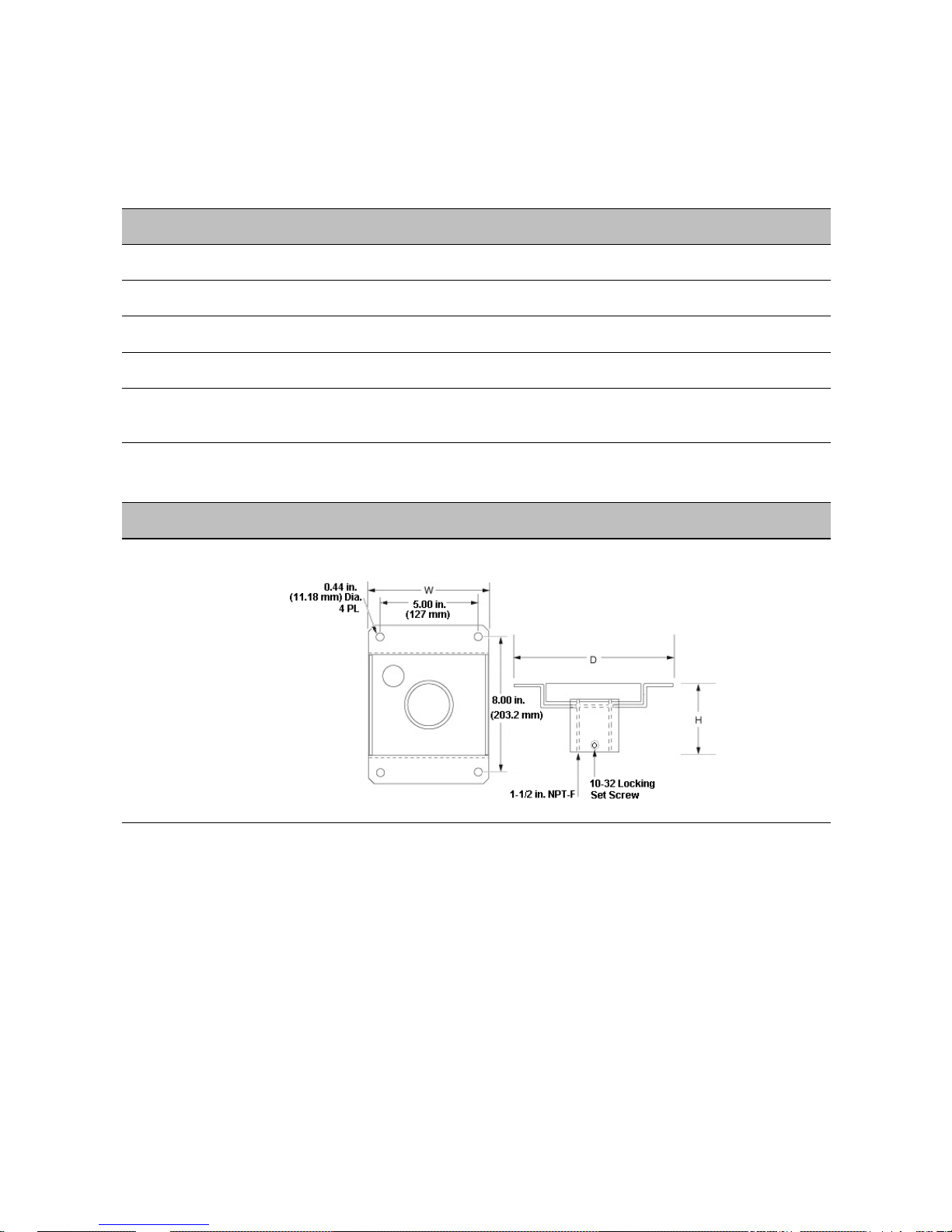
V-UWM Wall mount for indoor/outdoor
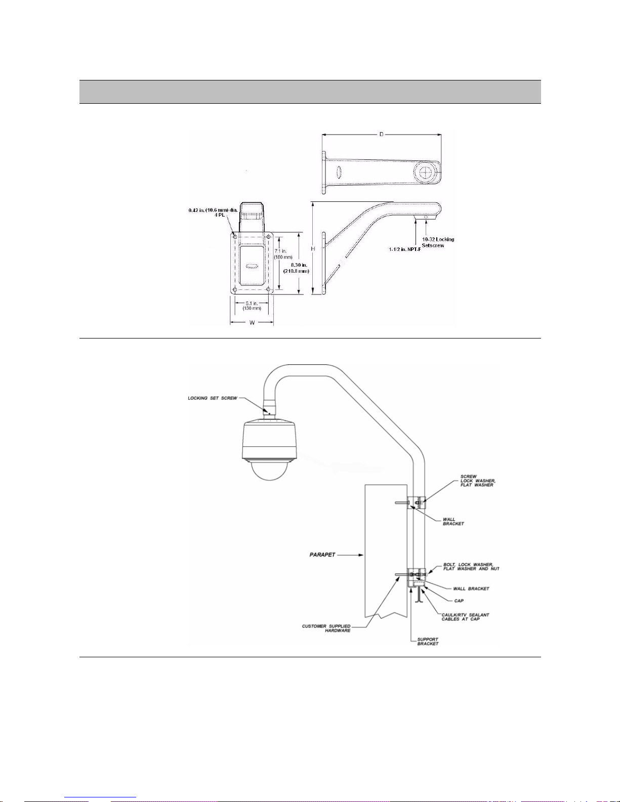
V-UPM-1 Parapet mount for outdoor
Verint Video Intelligence Solutions 6
Mounting Option Description
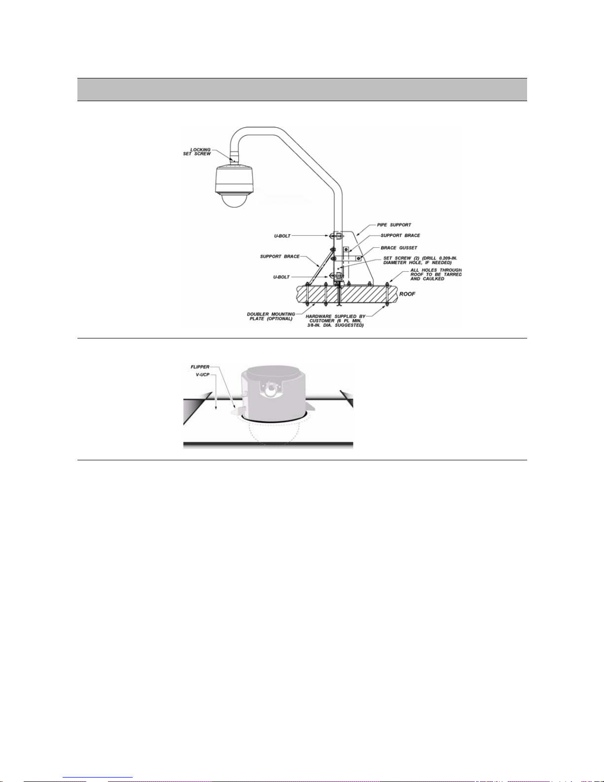
V-URM-1 Roof mount for outdoor
Nextiva S2800e Series User Guide
V-UCP Ceiling panel for indoor
Verint Video Intelligence Solutions 7

1: Overview
Mounting Option Description
V-WM Wall mount, short for indoor/outdoor
V-IC-MKT In-ceiling mount kit for indoor. For the installation instructions, see
page 14.
The following power supplies are optional:
Power Supply Description
S28PS-1 Power supply for a single indoor camera, 28V AC output,
2.15 amps
S28WPS-1 Power supply for a single outdoor camera, 28V AC output,
3amps
The equipment needed for the installation is:
Cable for power
Cables for alarms and relays
Verint Video Intelligence Solutions 8
Nextiva S2800e Series User Guide
Ethernet cable (straight-through or crossover) with an RJ-45 connector
Flexible conduit pipe for in-ceiling cameras (optional)
Hardware Overview
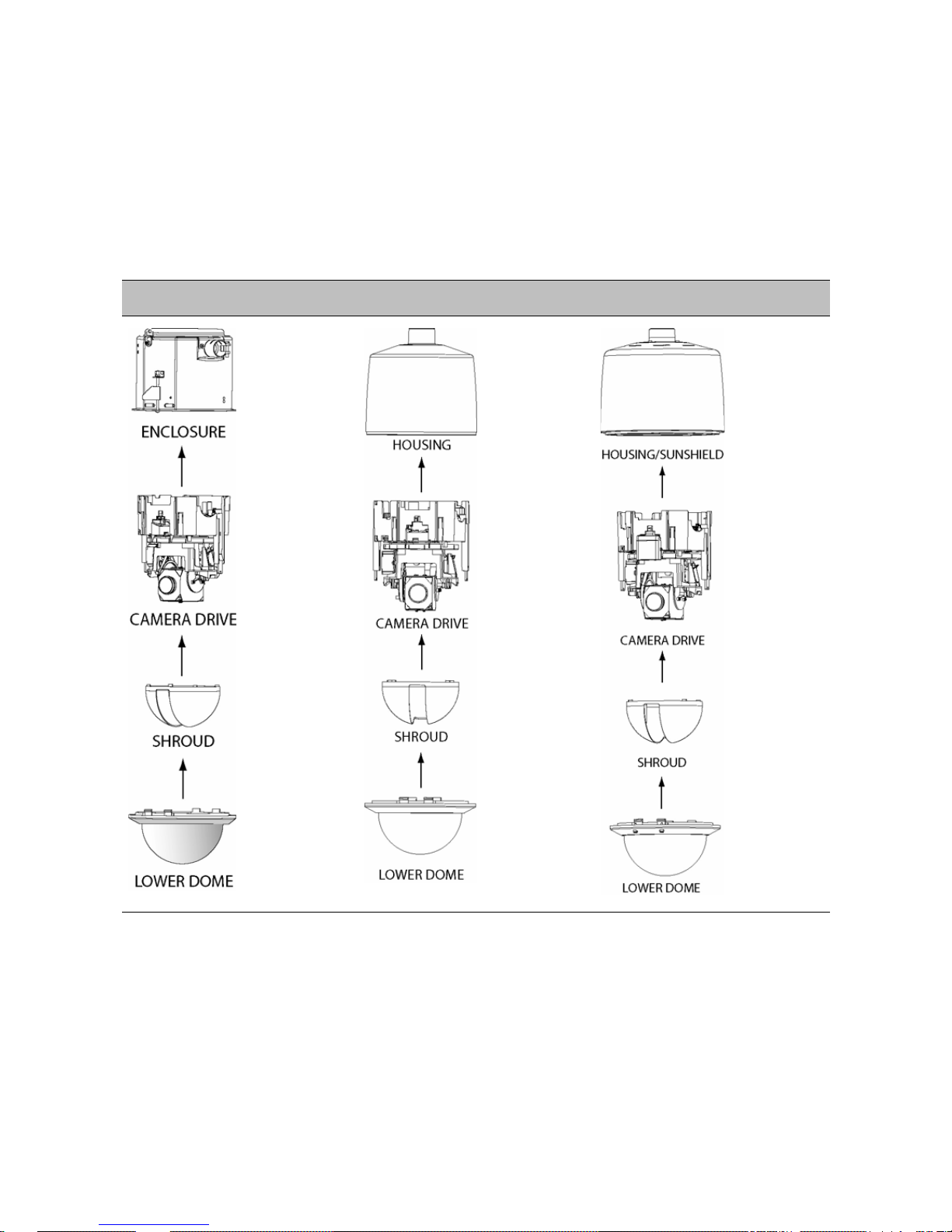
The components of the S2800e vary depending on the mounting type:
In-Ceiling Indoor Pendant Outdoor
The components are:
Enclosure. The enclosure is a metal shell that houses the camera drive for the
in-ceiling models. A safety cord and clip are provided to connect to the camera drive
during installation. In addition, a small hole is provided on the side of the enclosure for
connection of the safety cord of the lower dome. The package includes a removable top
cover, a 0.75-inch (19 mm) conduit fitting, and a pair of rotating flippers that give a
convenient and sturdy connection of the enclosure into the ceiling. For in-ceiling
installations that do not use a conduit pipe, a 0.75-inch (19 mm) strain relief fitting
Verint Video Intelligence Solutions 9

1: Overview
provides solid cable anchoring at the enclosure. The top of the enclosure holds an
interface board that can be unlatched or removed for easy access. All wiring is done to
this board.
Housing. The housing for the S2800e indoor pendant configurations is a molded plastic
protective cover for the camera drive; outdoor pendant configurations have a die-cast
aluminum housing with a sunshield. The housing has a 1.5-inch NPT pipe flange mount.
In addition, it is equipped with a safety cord and clip that are used to suspend the
camera drive during installation. Another safety cord connects the lower dome to the
housing. The top of the housing holds an interface board that can be unlatched or
removed for easy access. All wiring is done to this board.
Sunshield. The sunshield is pre-installed over the housing used on the outdoor
pendant version to minimize the effects of solar radiation.
Camera drive. The camera drive is comprised of an integral camera, pan-and-tilt
drive, and CPU. It is designed for easy “snap-in” installation into the enclosure or
housing. The camera drive quickly and accurately positions the camera in 360° of pan
angle and 95° of tilt angle. There are variations in camera type for zoom and color or
day/night usage. An additional thermostatically-controlled heater is provided for
temperature control on outdoor units.
Shroud. The shroud is a 5.4 inch (137 mm) textured black ABS plastic shell. It has a
1.4 inch (35.6 mm) slotted opening for the camera. This shroud conceals the position of
the camera and snaps onto the camera drive.
Lower dome. The lower dome is an assembly comprised of a 5.98 inch (152 mm)
diameter acrylic plastic shell, a trim ring and a safety cord. The lower domes for indoor
use have a smoked finish. Standard outdoor lower domes are clear and use fo ur screws
for additional support. All lower domes are anchored to the enclosure/housing by a
safety cord.
Verint Video Intelligence Solutions 10

Installing and
Configuring the S2800e
The steps required to prepare the S2800e camera for operation are:
Installing the Camera
Configuring the Camera
Uninstalling the Camera
Verint Video Intelligence Solutions 11
2: Installing and Configuring the S2800e
Installing the Camera
The installation procedure varies depending on the mounting type:
In-ceiling
Indoor pendant
Outdoor pendant
All S2800e models have the same procedure for wiring the interface board.
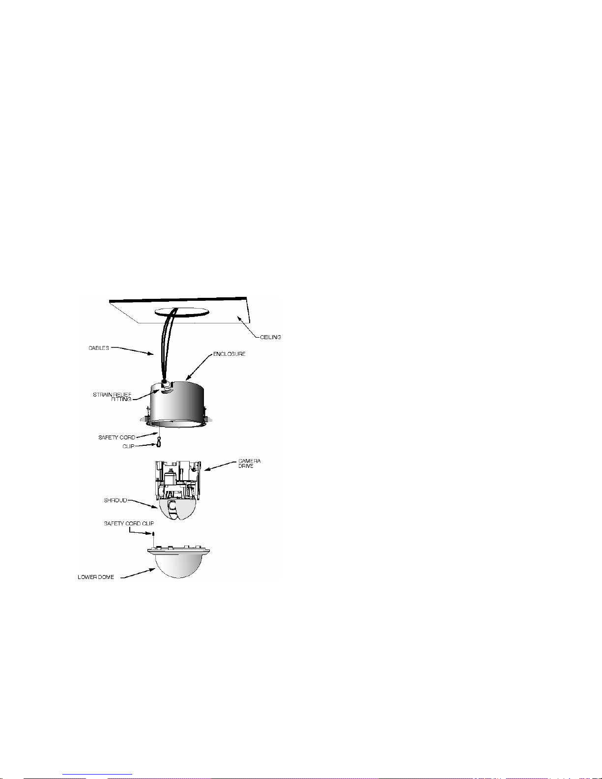
Installing an In-Ceiling Camera
The S2800eN-C22CA, S2800eN-C22, and S2800eN-C23 models mount in the ceiling and
rest on the ceiling material occupying the space between the lower ceiling and upper
building frame. All mounting hardware is provided.
The components to install are:
The ceiling material must provide a surface of suitable strength for a weight of 5.1 lb
(2.3 kg). For installations requiring additional support, see page 14.
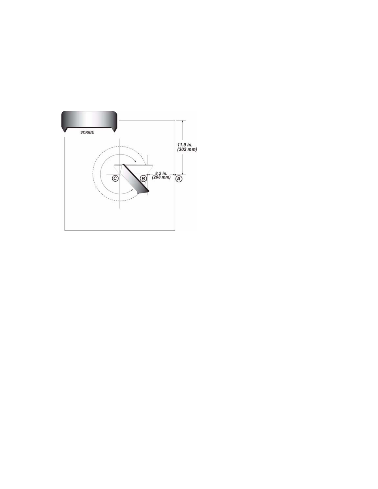
The package includes a small metal scribe to assist in marking an accurate hole size in a
ceiling tile.
The installation procedure involves the following main steps:
1. Marking the hole size with a scribe.
Verint Video Intelligence Solutions 12
Nextiva S2800e Series User Guide
2. Preparing the enclosure.
3. Installing the camera.
To mark the hole size with the scribe:
1. Place a ceiling tile on a large flat surface, face up.
2. Measure and make a small mark at position A from corner (11.9 inch/302 mm).
3. Measure and make a small mark at position B (8.2 inch/208 mm), placing the scribe as
perpendicular to the A-edge as possible.
4. Place the scribe across positions B and C. Rotate the scribe around center C for a full
turn.
To prepare the enclosure for an in-ceiling camera:
1. Using the circle made with the scribe, cut a 7-3/8-inch (187 mm) diameter hole in the
ceiling at the desired location.
Verint Video Intelligence Solutions 13
2: Installing and Configuring the S2800e
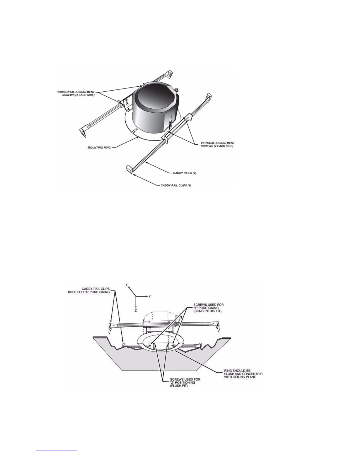
2. If the ceiling requires additional independent support for the S2800e, install the
optional in-ceiling mount kit (V-IC-MKT). It consists of a pre-assembled set of mounting
rails and folding ring:
a. Push the mount kit assembly up through the ceiling hole and unfold it.
b. Position the assembly squarely over the hole and fasten the caddy rail clips to the
existing frame. Remove adjacent tiles to access the clips.
c. Adjust the position of the caddy rail clips along the frame to obtain the best "X"
position.
d. Slide the assembly along the caddy rails to obtain the best concentric "Y" position.
Tighten the horizontal adjustment screws to secure the position.
e. With the ring concentric with the hole, slide the ring vertically along the support
slots to obtain the best flush fit in the ceiling. The ring should be firmly seated
against the tile without warping it.
3. Feed the flexible conduit pipe or cables down through the ceiling hole.
Verint Video Intelligence Solutions 14
 Loading...