

Verint Nextiva S2750eN, Nextiva S2750e Series, Nextiva S2750eP User Manual

Nextiva S2750e Series
User Guide
Covering the S2750eN and S2750eP
Firmware Release 4.80
April 2009

© 2009 Verint Systems Inc. All Rights Reserved Worldwide.
Unauthorized use, duplication, or modification of this document in whole or in part
without the written consent of Verint Systems Inc. is strictly prohibited. By providing
this document, Verint Systems Inc. is not making any representations regarding the
correctness or completeness of its contents and reserves the right to alter this document
at any time without notice. Features listed in this document are subject to change.
Verint Systems Inc. does not warrant, guarantee or make any representation regarding
the use or the results of the use of the information, links, tools, and materials in terms
of the accuracy, reliability, quality, validity, stability, completeness, currentness, or
otherwise of its content or products. The entire risk as to the use, results and
performance of information, links, tools and materials provided or referenced herein is
assumed by the user. Verint Systems Inc. shall not be liable for damages resulting from
the use, misuse or unlawful use of the information, links, tools, and materials contained
or referenced herein.
The Verint Systems Inc. products are protected by one or more of the following U.S.,
European or International Patents: USPN 5,659,768; USPN 5,689,442; USPN 5,790,798;
USPN 6,278,978; USPN 6,370,574; USPN 6,404,857; USPN 6,510,220; USPN
6,724,887; USPN 6,751,297; USPN 6,757,361; USPN 6,782,093; USPN 6,83 9,667;
USPN 6,952,732; USPN 6,959,078; USPN 6,959,405; USPN 7,0 47,296; USPN
7,149,788; USPN 7,155,399; USPN 7,203,285; USPN 7,216,162; USPN 7,21 9,138;
USPN 7,254,546; USPN 7,281,173; USPN 7,284,049; USPN 7,325,190; USPN
7,466,816; USPN 7,478,051; USPN RE40,634; and other provisional rights from one or
more of the following Published US Patent Applications: US 11/394,408; US 11/771,499;
US 11/396,514; US 11/772,440; US 11/565,943; US 11/565,946; US 11/565,948;
US 11/540,739; US 11/540,086; US 11/541,313; US 11/541,252; US 11/540,282;
US 11/529,947; US 11/540,785; US 11/540,736; US 11/540,904; US 11/540,353;
US 11/608,340; US 11/608,350; US 11/608,358; US 11/567,808; US 11/692,983;
US 11/693,933; US 11/693,923; US 11/693,828; US 11/567,852; US 11/608,440;
US 12/015,621; US 11/540,322; US 11/924,201; US 11/616,490; US 11/621,134;
US 11/752,458; US 11/712,933; US 11/824,980; US 11/729,185; US 11/804,748;
US 11/831,260; US 11/395,992; US 11/359,319; US 11/359,195; US 11/359,357;
US 10/832,509; US 11/742,733; US 11/831,257; US 11/831,250; US 11/691,530;
US 11/479,267; US 11/529,942; US 11/768,349; US 11/540,281; US 10/633,357;
US 11/693,899; US 11/479,056; US 11/529,132; US 11/540,320; US 11/037,604;
US 11/529,842; US 11/540,171; US 11/478,714; US 11/529,946; US 11/868,656;
US 11/776,659; US 11/090,638; US 11/410,004; US 10/771,315; US 10/771,409;
US 11/540,900; US 11/528,267; US 12/118,781; and other U.S. and International
Patents and Patents Pending.
VERINT, the VERINT logo, ACTIONABLE INTELLIGENCE, POWERING ACTIONABLE
INTELLIGENCE, WITNESS ACTIONABLE SOLUTIONS, STAR-GATE, RELIANT, VANTAGE,
X-TRACT, NEXTIVA, ULTRA, AUDIOLOG, WITNESS, the WITNESS logo, IMPACT 360, the
IMPACT 360 logo, IMPROVE EVERYTHING, EQUALITY, CONTACTSTORE, and
CLICK2STAFF are trademarks or registered trademarks of Verint Systems Inc. or its
subsidiaries. Other trademarks mentioned are the property of their respective owners.
www.verint.com/videosolutions
Publication date: April 2, 2009
Publication revision: D

Contents
Preface ................................................................................................................ v
Chapter 1 Overview ..........................................................................................1
About the S2750e Series ...................................................................................2
Key Features ................................... .. ............................................. ............2
Security ..................................................................................................... 2
Frame Rate and Performance ........................................................................2
Installation Kit .......................... ......................... .. .. .. .......................... .. .. .. .. ......4
Hardware Overview ..........................................................................................4
Chapter 2
Mounting the Camera ........................................................................................7
Adjusting the Image .......................................................................................12
Configuring the Camera ..................................................................................14
Chapter 3
Installing or Upgrading ActiveX Controls ............................................................ 20
Viewing the Quick Status .................................................................................22
Configuring the Device ....................................................................................24
Viewing Live Video ..........................................................................................39
Maintaining the Device ....................................................................................41
Chapter 4
Updating the Firmware ....................................................................................45
Performing a Reset ......................................................................................... 45
Recognizing the Status LED Conditions .............................................................. 46
Using the Command Line Interface .................................... .. ....................... ...... 47
Mounting and Configuring the IP Camera .........................................6
Preparing the Camera ..................................................................................7
Installing the Camera ..................................................................................9
Setting Network Parameters .......................................................................15
Performing a Point-to-Point Connection ........................................................ 17
Using the Web Interface .................................................................19
Configuring Access Management ................................................................. 24
Viewing the System Status .........................................................................27
Configuring the Network ............................................................................28
Configuring Video ..................................................................................... 29
Looking at Video Status ................................. ......................... .. .. ... ............ 34
Configuring VSIP .......................................................................................35
Configuring System Time ...........................................................................36
Configuring HTTP (Webserver) ....................................................................37
Configuring LED State ............................................................................... 38
Maintaining and Troubleshooting the IP Camera ............................44
Accessing the CLI .....................................................................................47
Configuring Quality of Service .....................................................................48
Appendix A
Appendix B
Appendix C Technical Specifications ................................................................ 54
Verint Video Intelligence Solutions iii
Factory Default Configuration .......................................................50
DHCP Support and APIPA ..............................................................52

Contents
Glossary ............................................................................................................. 57
Index .................................................................................................................62
Compliance ........................................................................................................64
United States Statement for FCC .......................................................................65
Industry Canada Statement ............................. .. .. .. .. .......................... .. .. .. .. ......65
Europe EN 55022 Statement ............................................................................66
RoHS Declaration of Compliance .......................................................................67
iv Verint Video Intelligence Solutions

Preface
The Nextiva S2750e Series User Guide presents the information and procedures on
installing, configuring, and using the Nextiva® S2750e series IP cameras.
Audience
This guide has been prepared for the following audience:
Managers
IT system administrators
Engineers
Technicians
This guide assumes that you are familiar with:
Installation and manipulation of electronic equipment
General use of computers
Local area networks (LANs) and basic IP data communication concepts and practices
Camera configuration
Web browsers
Microsoft Windows operating systems
Reference
In addition to this guide, the following documentation is also available:
Nextiva S2750e Series Installation Guide
Verint SConfigurator User Guide
Nextiva S2750e Series Release Notes
A paper copy of the installation guide is included with your order.
How to Contact Us
The following Web sites and e-mail addresses provide information and support for Verint
Video Solutions and the Nextiva Intelligent Edge Device product line.
Find general information on Verint Video Solutions, including marketing material and
product information at www.verint.com/videosolutions
Download the documentation of the Intelligent Edge Devices at www.verint.com/manuals
Download firmware from the Verint Video Solutions partner extranet at
http://vvs.verint.com
Send your questions or comments on the current document, or any other Nextiva user
documentation, to our documentation feedback team at
documentationfeedback@verint.com
.
.
.
.
Verint Video Intelligence Solutions v

Preface
Find contact information for the Verint Customer Service team, by phone or e-mail, or fill
out a Web request for support with a specific issues at www.verint.com/videoservice. For
immediate assistance, contact the Customer Service team:
Location Telephone E-mail
USA and Canada 1-888-747-6246 vissupport@verint.com
Central and Latin
America
Europe, Middle East,
and Africa
Asia/Pacific
Hong Kong
Singapore
+1-631-962-9202 vissupport@verint.com
+44 (0) 845-843-7333 customersupport.emea@verint.com
+49 (0) 4321-269 81 36 mobilesupport@verint.com
(Transit applications only)
APAC_VIS_Services@verint.comp
+852 2797 5678
+65-68266099
vi Verint Video Intelligence Solutions
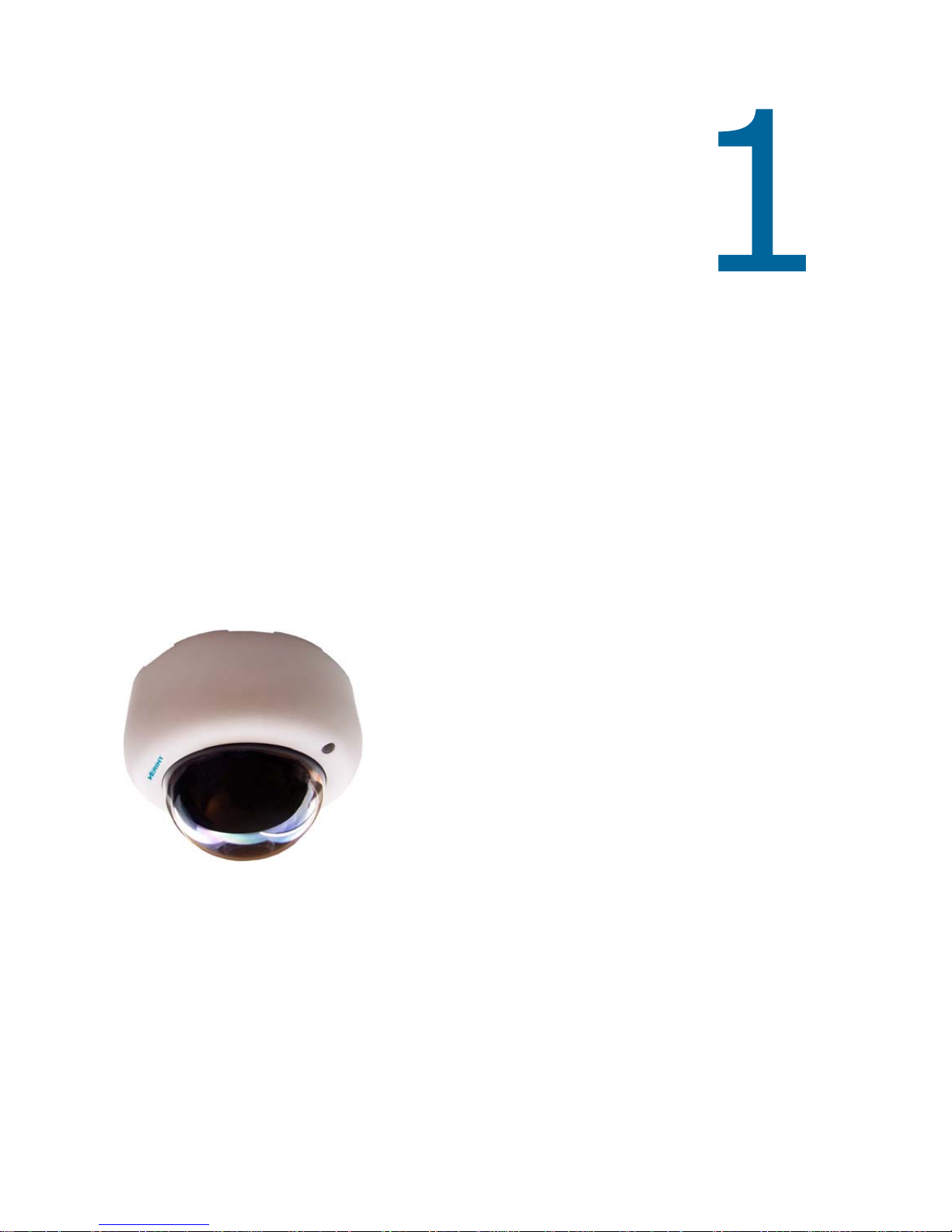
Overview
The Nextiva S2750e series contains IP mini-dome cameras with triple axis lens rotation for
flexible installation. The series offers a high resolution image sensor and an auto-iris
varifocal lens.
The S2750e series delivers dual stream video at up to 30 frames per second in NTSC (25 in
PAL). The following compression modes (also called codecs—coder/decoder) are available:
a proprietary MPEG-4-based mode, the MPEG-4 ISO 14496-2 compliant mode, and MJPEG
(Motion JPEG).
Y ou can use the S2750e series edge devices in point-to-point contexts as well as with video
management and storage applications. Furthermore, they enable configuration, video
viewing, and maintenance from web browsers.
The overview covers:
About the S2750e Series
Installation Kit
Hardware Overview
Verint Video Intelligence Solutions 1

1: Overview
About the S2750e Series
The S2750e series offers many models to cover your system needs:
S2750eN—An IP camera working in the NTSC video standard
S2750eP—An IP camera working in the PAL video standard
Unless otherwise specified, the word S2750e refers to any of these devices.
Key Features
The S2750e offers the following features:
One analog video output for aiming and focusing during installation
The choice of either power over Ethernet (PoE) or 12V DC
Dual video encoding
Up to 30 frames per second with the MPEG-4 and MJPEG codecs
480 TVL, 1/3 inch Sony CCD sensor
4 to 9 mm varifocal lens, with DC auto-iris
Triple axi s lens adjustments
Clear (default) or smoked cover
Integration with the Nextiva enterprise video management solution
Security
Every camera comes with a unique SSL (Secure Sockets Layer) certificate for securing its IP
link. SSL is a commonly used protocol for managing the security of IP message
transmission. If enabled, the SSL protocol secures I/O and proprietary VSIP communication
data. It does not apply to video transmission.
Frame Rate and Performance
The available video frame rates of each encoder IP camera are:
NTSC—1 to 7, 10, 15, or 30 frames per second (fps)
PAL—1 to 6, 8, 12, or 25 fps
The composite video signal of the camera is sent to two separate encoders. You can
customize each encoder to meet your system needs, for instance in terms of frame rate and
resolution. Here are typical scenarios regarding encoder use:
Scenario Encoder 1 Encoder 2
point-to-point point-to-point unused
2 Verint Video Intelligence Solutions
unused point-to-point

Nextiva S2750e Series User Guide
Scenario Encoder 1 Encoder 2
point-to-point and web interface web viewing at rate A point-to-point at rate B
web viewing and
unused
point-to-point at rate C
video management software view at rate D record at rate E
Note: You should not use the web interface and a video management software at the
same time to avoid configuration conflicts.
Each video endoder of an S2750e camera can have the following performances:
Resolution Number of
Columns
Number of
Lines
Maximum Frame Rate, in Frames per
Second Using the NTSC (PAL) Format
NTSC PAL MPEG-4
Based
MPEG-4
ISO 14496-2
MJPEG
Compliant
QCIF 176 128 144 30 (25) 30 (25) 30 (25)
CIF 352 240 288 30 (25) 30 (25) 30 (25)
2CIF 704 240 288 30 (25) 30 (25) 30 (25)
4CIF 704 480 576
30 (25)
2
15 (12.5) 30 (25)
All lines 352 480 576 30 (25) 30 (25) 30 (25)
2/3 D1 480 480 576 30 (25) 30 (25) 30 (25)
VGA 640 480 480 30 (25) 15 (12.5)
1
Without noise and other factors affecting quality.
2
With low motion only.
30 (25)
These performances can be achieved using single-stream encoding. For dual encoding
values, refer to the Nextiva Intelligent Edge Devices Single-Dual Stream Performance
document, available on the extranet (Community Links > Technical Briefs > Nextiva
Intelligent Edge Devices).
1
Verint Video Intelligence Solutions 3

1: Overview
Lens
Dome cover
Outer case
Installation Kit
The package contents are:
Item Description
Camera S2750eN or S2750eP
Video output adaptor A 2.5 mm to BNC video output adaptor (3 foot/1m long)
Rubber cap A rubber cap for the cable entry
Printed material The Nextiva S2750e Series Installation Guide
Options
Power-over-Ethernet
(PoE) kit
12V DC external power
supply
Dome cover A smoked dome cover
An IEEE 802.3af class 3 injector and power cord
A universal power supply
Hardware Overview
The S2750e has been designed for indoor use. It cannot be used outdoors.
The side view of the camera shows the following parts:
The lens
The dome cover
The outer case
4 Verint Video Intelligence Solutions
Nextiva S2750e Series User Guide
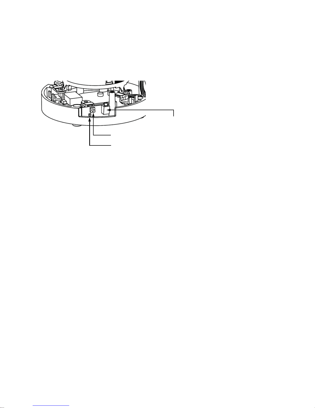
Status LED
Jack for video output
Reset button
The service board contains:
A status LED
An 2.5 mm jack for video output
A reset button
The dome base also includes a network (RJ-45) cable and a power cable.
Verint Video Intelligence Solutions 5

Mounting and
Configuring the IP
Camera
The steps required to prepare your S2750e camera for operation are:
Camera mounting
Image adjustment
Basic configuration
Remember that the S2750e camera is an indoor product that should not be used in an
outdoor environment.
Note: The S2750e series device must be installed by certified professionals.
Verint Video Intelligence Solutions 6

Nextiva S2750e Series User Guide
Mounting the Camera
You can mount the S2750e camera the following ways:
Mounting directly on the ceiling or wall
Mounting on an electrical box (North America box styles only)
The mounting procedure involves the following main steps:
1. Preparation
2. Physical installation
To install the camera, you need the following equipment:
A Phillips screwdriver
Four mounting screws, if the camera goes on the ceiling or wall:
Screw size: #10
Maximum screw head diameter: 0.37 inch (9.5 mm)
Maximum screw head height: 0.14 inch (3.5 mm)
Casing height: 0.9 inch (23 mm)
Two mounting screws, if the camera goes on an electrical box
Note: Select the screw type depending on the material on which the device will be
mounted.
Preparing the Camera
The first step in mounting the camera is preparing the surface and taking the camera apart.
Verint Video Intelligence Solutions 7
2: Mounting and Configuring the IP Camera
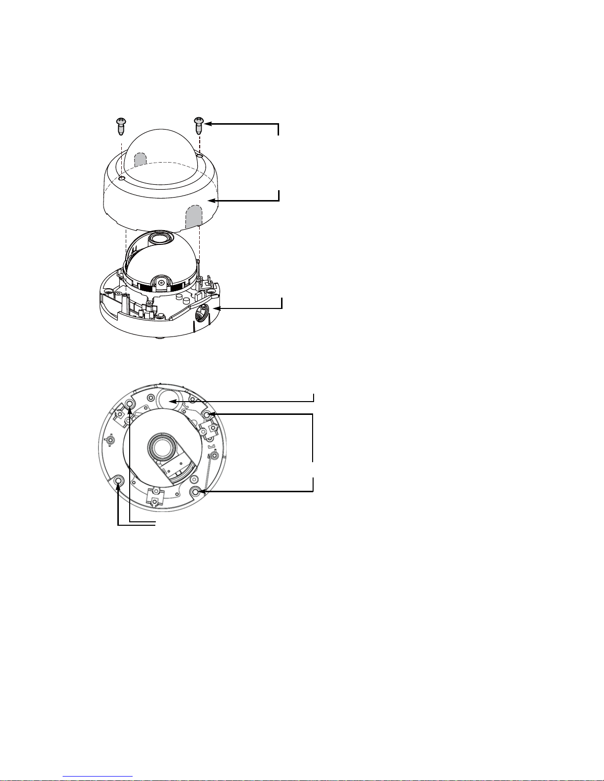
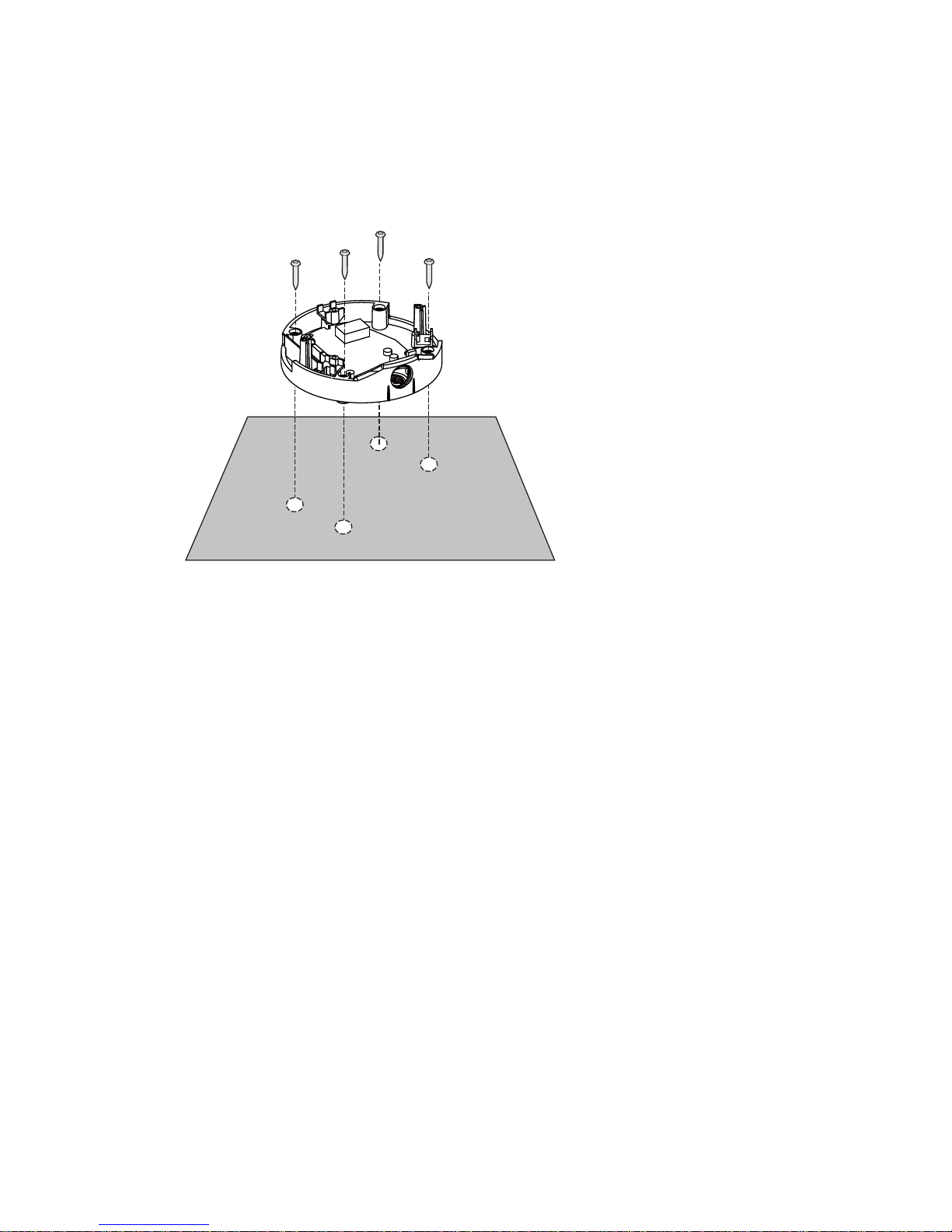
Outer case
Outer case screw
Dome base
Mounting holes
Mounting holes
Base cable entry
To prepare the camera for mounting:
1. Remove the outer case by loosening the two case screws with a Phillips screwdriver.
2. If you are mounting the camera on the ceiling or wall, mark the four positions for fixing
the dome base on the mounting surface, then make the four holes.
If you are mounting the camera on an electrical box, you will use only two of the four
mounting holes on the dome base.
8 Verint Video Intelligence Solutions
Nextiva S2750e Series User Guide
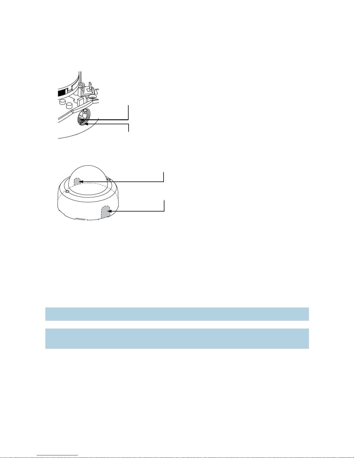
Base cable entry
Side cable entry
0.5 inch side entry
0.75 inch side entry
3. If you are using the base cable entry, replace the plastic cap by the supplied rubber
cap, then make a hole at the desired location on the mounting surface. The size of both
cable entries is 3/4” NPT2.
4. If you are using the side cable entry on the dome base, open the desired hole on the
outer case with pliers. Insert the supplied rubber cap in the dome cable entry.
Installing the Camera
The installation process varies depending on your supply power: PoE or 12V DC.
Power-over-Ethernet (PoE) enables you to power the camera and establish its Ethernet
connection in a single operation. The optional PoE kit sold by Verint contains two items: an
injector and a power cord. The connection procedure may vary if you use another PoE kit;
refer to the PoE kit documentation for more information.
Verint also offers a universal 12V DC power supply as part of your package. For any other
power supply, refer to the manufacturer documentation for the proper wiring scheme.
Warning: Never use PoE and 12V DC at the same time. It may damage the device.
Note: The camera must be powered by a listed power supply that is marked “LPS,”
”Limited Power Source,” or “Class 2”.
To perform a 12V DC power connection with the universal power supply sold by
Verint:
1. If the electrical plug installed on the power supply is the right one for the country of
operation, go to step 4.
2. Remove the installed plug by push in g the PUSH button and keeping it pushed while
turning the plug in the counterclockwise direction.
Verint Video Intelligence Solutions 9
2: Mounting and Configuring the IP Camera
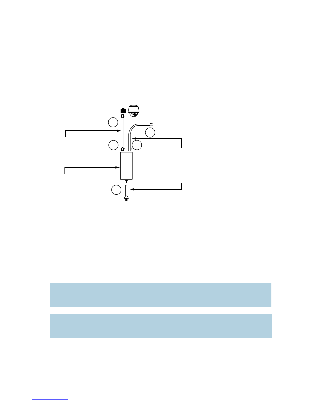
1
2 3
4
J2
DATA
J1
DATA & PWR
5
RJ-45
Power cord
PoE injector
Straight-through
Ethernet cable
Ethernet cable (straight-through or
crossover)
3. Insert the required plug on the power supply then turn it in the clockwise direction until
you hear a click.
4. Tie together the power supply wire with the dashed white lines and the black wire on
the camera using a splice.
5. Tie together the other power supply wire and the red wire on the camera using a splice.
6. Power the camera by connecting the electric plug into the outlet.
To connect the PoE kit sold by Verint:
1. Plug a straight-through Ethernet cable into the network (RJ-45) connector of the
2. Plug the other end of the cable into the DATA & PWR port of the injector.
3. Connect another Ethernet cable (straight-through or crossover) into the DATA port of
4. Connect the other end of the second cable into an Ethernet equipment.
5. Power the device by plugging the power cord between the injector and the outlet.
device.
the injector.
The crossover cable directly connects the IP camera to a computer; use a
straight-through cable to connect the IP camera to a hub or a switch for integration
with the network.
Warning: To avoid damaging your Ethernet equipment, ensure that the cable is
connected into the DATA port of the PoE injector, and not in the DATA & PWR
port.
Note: The combined length of the two Ethernet cables cannot exceed 328 feet
(100 meters). For example, if you used an 82-foot (25m) cable in step 1, the
maximum length of the second cable is 246 feet (75m).
10 Verint Video Intelligence Solutions
Nextiva S2750e Series User Guide
To install the camera:
1. Mount the camera:
On the ceiling or wall, install the dome base on the mounting surface, using four
screws (not supplied); for their specification, see page 7.
On an electrical box, use two screws (not supplied).
6. Feed the cables through the bottom or side hole on the outer case. Ensure that the
cables exit out of the hole without being crushed.
7. If the camera uses 12V DC:
a. Establish its Ethernet connection by plugging a cable (straight-through or
crossover) between the RJ-45 connector at the end of the Ethernet cable and a
device.
The crossover cable directly connects the IP camera to a computer; use a
straight-through cable to connect the IP camera to a hub or a switch for integration
with the network.
b. Tie together the camera power wires to those of the power supply (see page 9).
8. If the camera uses PoE, perform the power and Ethernet connection (see page 10).
Verint Video Intelligence Solutions 11

2: Mounting and Configuring the IP Camera
Adjusting the Image
After installing the camera, adjust the image to point to the location to be monitored and to
control parameters for low light scenes.
You can perform the following adjustment operations:
Direction (every axis can be adjusted at steps of 1.5 degrees):
Pan: 360 degrees
Tilt: 90 degrees
Rotation: 360 degrees
Field angle (zoom)
Focus
Back light compensation (BLC): To compensate in cases where a subject with a large
amount of background light would otherwise be obscured by blooming or silhouetting.
Turbo mode for automatic gain control (AGC): To amplify the video signal more than
with the normal AGC setting; this normal setting is the default in the S2750e camera.
AGC helps maintain a constant video signal even if there are changes in brightness.
To adjust the image:
1. Power the camera.
2. Remove the dome cover by pressing firmly then pulling.
3. To adjust the image using live video, use either an analog test monitor or the live video
feature of the web interface (see page 39):
To use a test monitor, plug its connector into the 2.5 mm video jack on the service
board of the camera, using the supplied video output adaptor.
To view live video using the web interface, establish the Ethernet connection of the
camera.
12 Verint Video Intelligence Solutions
Nextiva S2750e Series User Guide
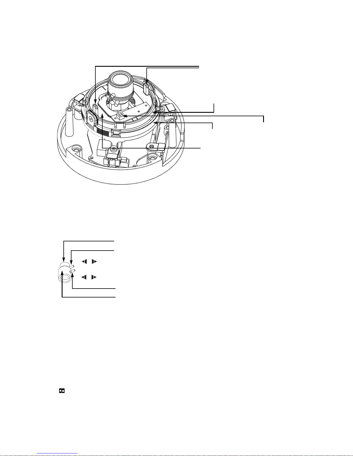
Rotation knobs
Tilt rim
Pan rim
TOP mark
DIP switches for BLC
and AGC
.
7
4
Zoom knob
Zoom adjustment ring
Focus adjustment ring
Focus knob
ON
21
BLC
AGC
4. Adjust the pan angle by turning the pan rim to the right or to the left (360 degrees of
liberty). You will hear clicks as you turn the rim.
5. Adjust the tilt angle by pushing the tilt rim to the right or to the left (90 degrees of
liberty). You will hear clicks as you push the rim.
6. Using the two rotation knobs, position the TOP mark on the sensor module so that the
arrow points towards the top of the image.
7. Adjust the field angle and the focus with the adjustment knobs on the lens:
a. To zoom out to see the full spectrum, move the zoom knob towards the W (wide)
mark.
b. To concentrate on a specific area, move the zoom knob towards the T (telephoto)
mark.
c. To focus on a near object, move the focus knob towards the N (near) mark.
d. To focus on a far object, move the focus knob towards the infinite mark.
8. To activate back light compensation for adjusting the exposure level to allow more
detail to be viewed, put the BLC DIP switch to the ON position.
Verint Video Intelligence Solutions 13
2: Mounting and Configuring the IP Camera
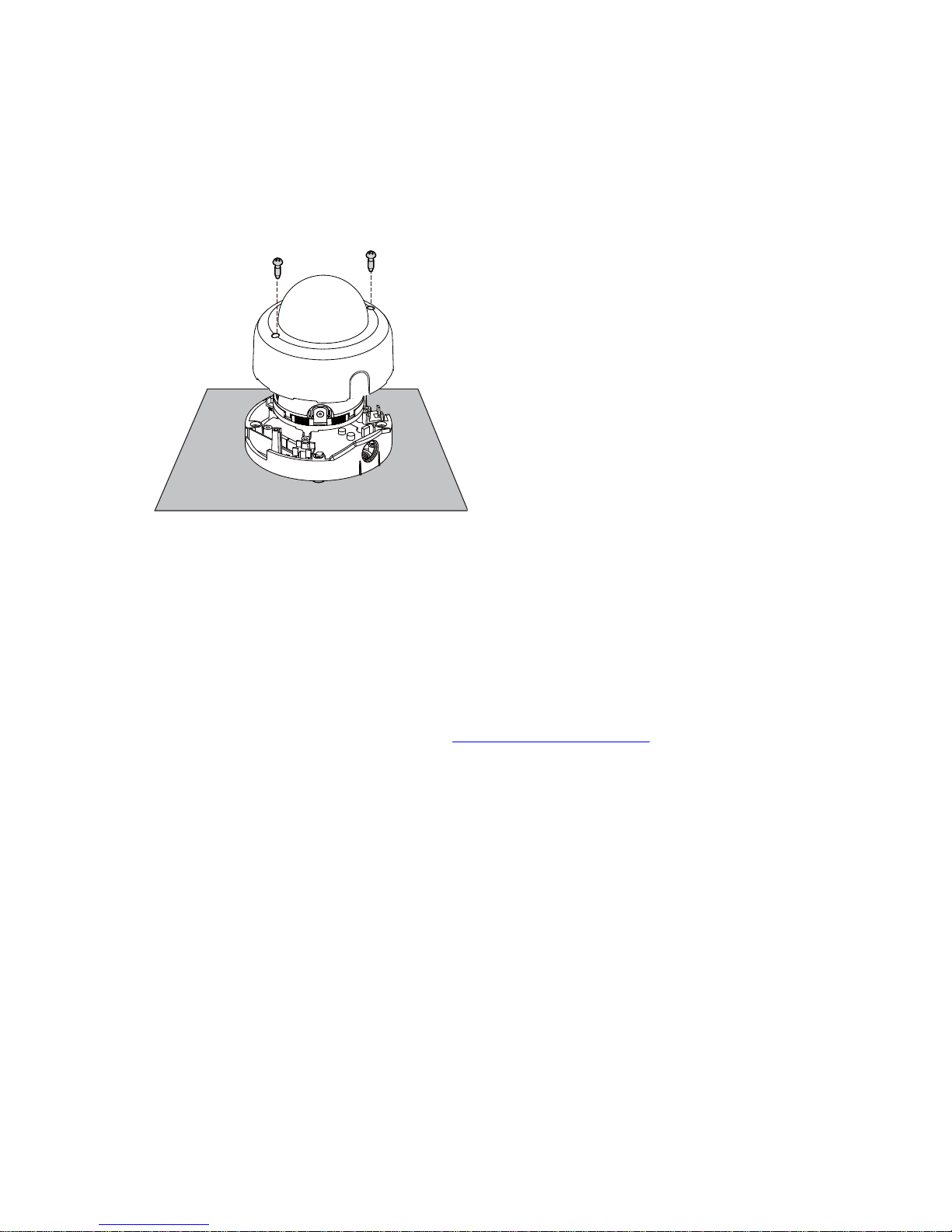
9. To activate the turbo mode of the automatic gain control, put the AGC DIP switch to the
ON position.
10. Put back the dome cover, taking into consideration the lens direction for the cover
opening.
11. Place the outer case back and secure the whole camera.
Configuring the Camera
The configuration steps to execute are:
Setting network parameters
Establishing a point-to-point connection between the camera and a receiver device, if
required
Device configuration requires the use of the proprietary SConfigurator tool. Its latest
version is included on the Verint web site (www.verint.com/manuals
executable file (SConfigurator.exe) to the hard disk of your computer.
The minimum hardware and software requirements for the host computer needed to
configure the edge device are:
An Ethernet network card
Internet Explorer 6.0 or higher
Microsoft DirectX 8.1 or higher
Windows 2000 Service Pack 2 or higher, or Windows XP Service Pack 2 or higher
). You need to copy its
14 Verint Video Intelligence Solutions
Nextiva S2750e Series User Guide
Setting Network Parameters
The first step in configuring is to provide a typical initial configuration of its network
parameters (including its IP address) to ensure compatibility with an existing network.
Note: To work properly , devices on the same network must have unique IP addresses. The
device will not prevent you from entering a duplicate address. However, its system
status LED will turn to flashing red (1-second interval); then the device will use its
default address. You then need to configure it with a proper IP address.
After providing the network settings, you complete the configuration with SConfigurator,
the web interface, or your video management software.
To set the network parameters:
1. Power the camera and establish its Ethernet connection.
Warning: Never use PoE and 12V DC at the same time. It may damage the camera.
2. Start SConfigurator by double-clicking SConfigurator.exe on your hard disk. The
SConfigurator window appears.
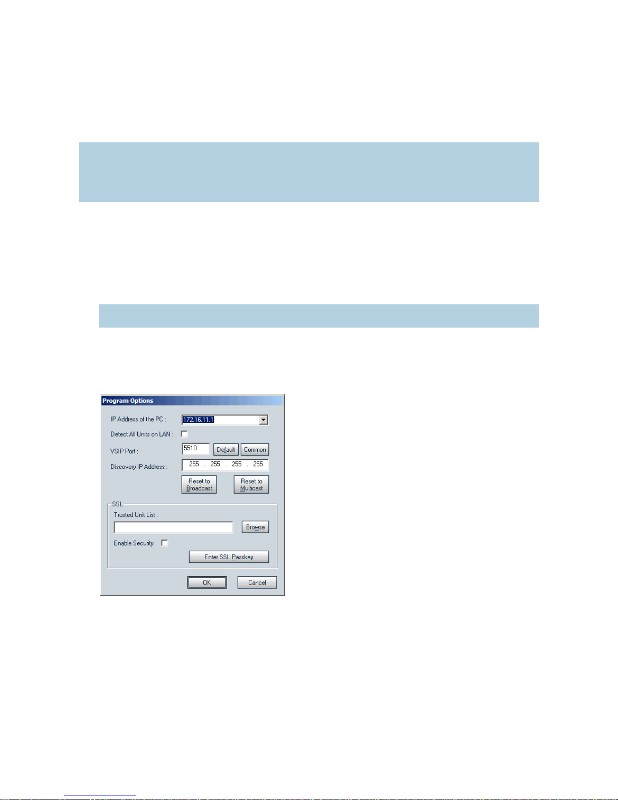
3. In the General tab, click Program Options. The Program Options window appears.
4. Check Detect All Units on LAN.
5. Ensure that the VSIP Port is 5510; otherwise, click Default.
6. Ensure that the Discovery IP Address is 255.255.255.255; otherwise, click Reset to
Broadcast.
7. Click OK.
Verint Video Intelligence Solutions 15
2: Mounting and Configuring the IP Camera
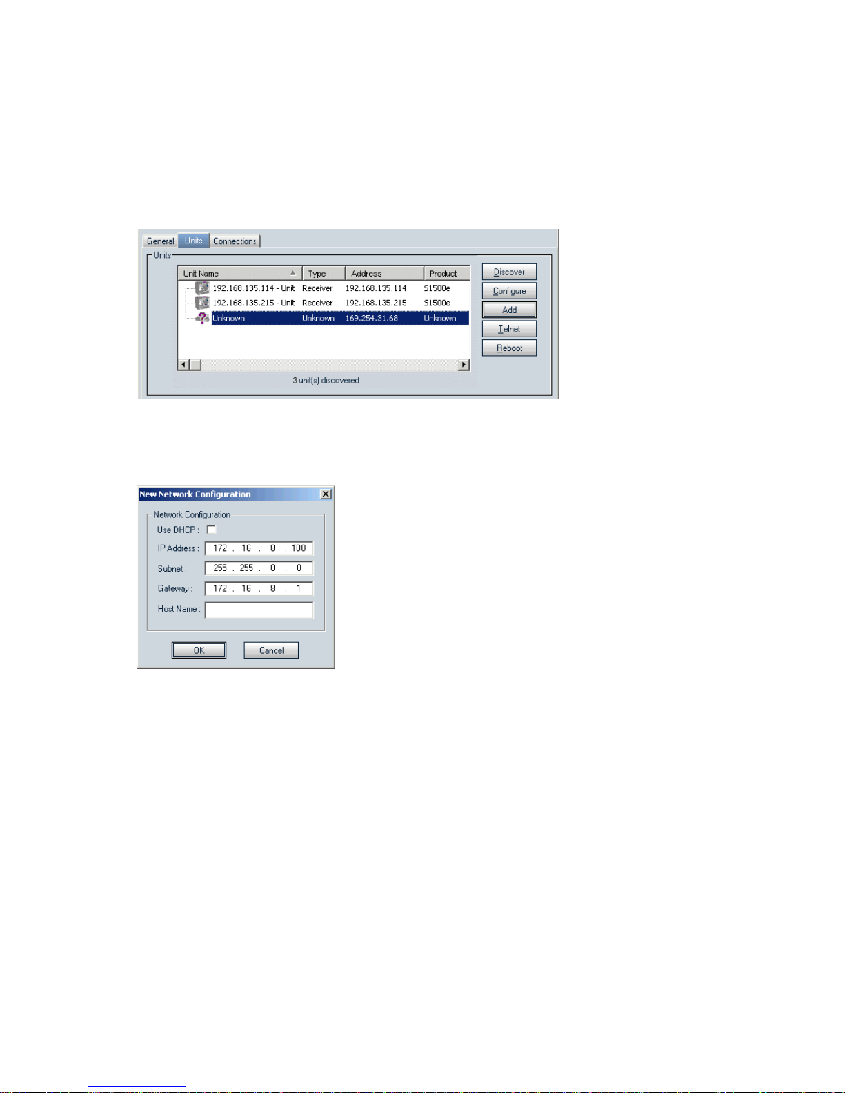
8. Select the Units tab, then click Discover.
A device of type “Unknown” with a 169.254.X.Y IP address appears in the list; it
corresponds to your new device. This default IP address is based on the APIPA
(Automatic Private IP Addressing) addressing scheme.
X and Y are relative to the MAC
(Media Access Control) address of the device; for more information about APIPA, see
page 52.
9. Select the unknown device, then click Configure.
10. In the Reconfigure unit? confirmation window, click Yes. The New Network
Configuration window appears.
11. If you have a DHCP (Dynamic Host Configuration Protocol) server on your network,
check Use DHCP. Otherwise, enter the IP address, subnet mask, and gateway of the
device, as provided by your network administrator. For more information about DHCP,
see page 52.
12. Click OK. The device reboots with its ne w network configuration.
13. In the Units tab, click Discover to update the list of devices. The new S2750e device
appears.
The S2750e initial configuration is now complete. You perform further configuration with
the web interface (see page 19) or your video management software.
16 Verint Video Intelligence Solutions
Nextiva S2750e Series User Guide
Transmitter (camera) Receiver
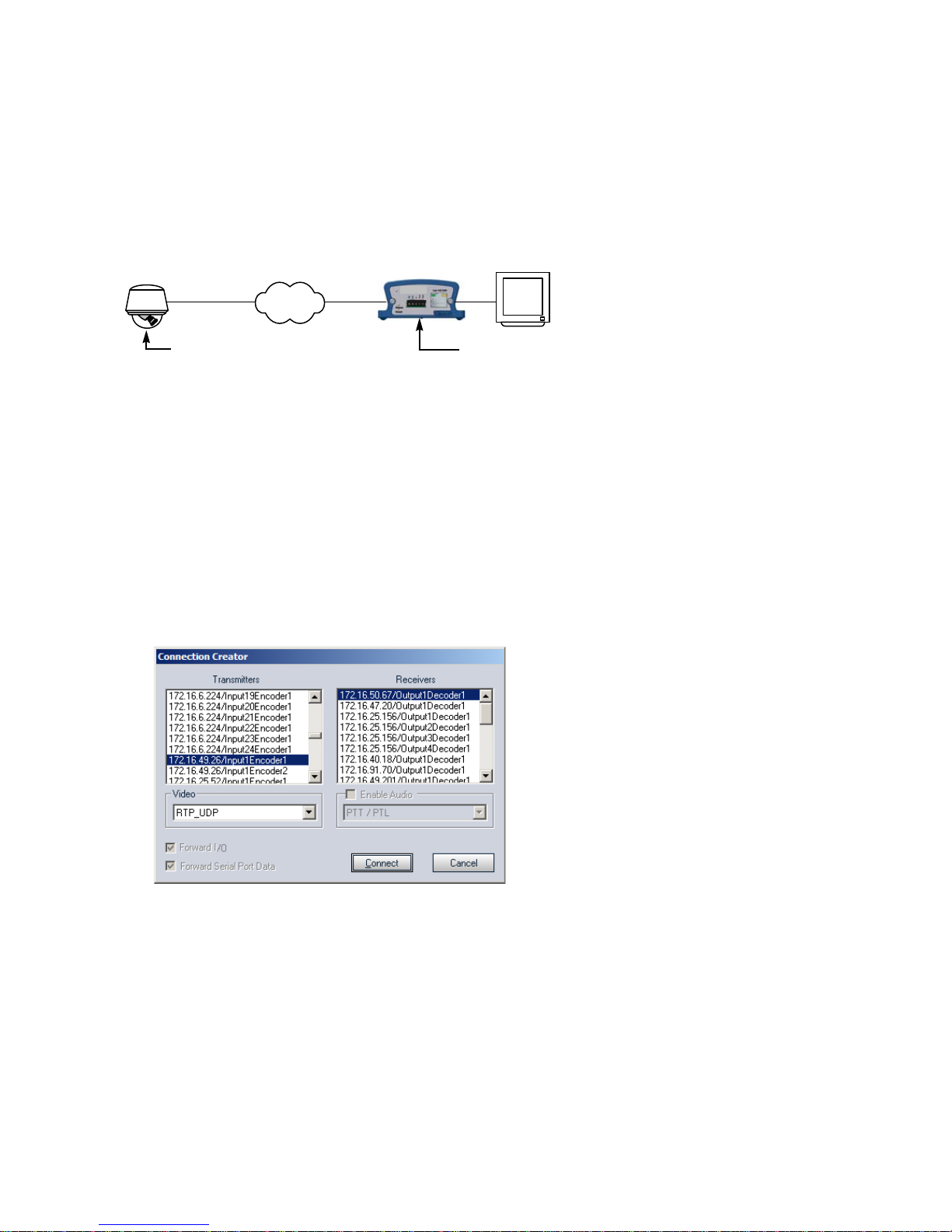
Performing a Point-to-Point Connection
c
A point-to-point connection is the association of a transmitter and a receiver to view video
coming from an analog camera on an analog monitor. The IP camera acts as a transmitter
in this context. The Nextiva receivers are the S1970e-R and S1504e-R. You can connect
each of these receivers to up to four transmitters, to create a maximum of four different
point-to-point connections. Here is a single connection:
You can also use a point-to-point connection to transfer audio, input/output, or serial port
data, if the transmitter and receiver have these features.
Typically, both devices sit on the same IP subnet as SConfigurator and have the same VSIP
port; to access other devices, refer to the device discovery section in the Verint
SConfigurator User Guide.
To associate a transmitter and a receiver in a point-to-point connection:
1. Start SConfigurator.
2. In the Units tab, discover the desired devices. The discovered devices appear in the
Units box.
3. Select the Connections tab, then click Add. The Connection Creator window appears.
4. Select a transmitter in the left column and a receiver in the right one.
In the Transmitters column, you have access to the two encoders of each input; the
video stream is the same for both. Encoder1 is always reserved for viewing live video
with the web interface, therefore you should use Encoder2 for point-to-point
connections; however, you can use the same encoder for both functions if you want the
same resolution and frame rate.
Verint Video Intelligence Solutions 17
 Loading...