

Verint nextiva s17xxe series User Manual

Nextiva Multiport
S17XXe Series User
Guide
August 2006 Firmware Release 4.60
AMERICAS
330 South Service Road
Melville, NY 11747
+1 631 962 9600
info@verint.com
www.verint.com/videosolutions
EMEA
241 Brooklands Road
Weybridge, Surrey KT13 0RH
+44 (0)1932 839500
marketing.emea@verint.com
www.verint.com/videosolutions
APAC
61 Hoi Yuen Road, Kwun Tong
Kowloon, Hong Kong
+852 2797 5678
marketing.apac@verint.com
www.verint.com/videosolutions


Nextiva Multiport S17XXe Series
Covering the S1704e-AS, S1708e, S1708e-AS,
S1712e, and S1724e
Firmware Release 4.60
User Guide
Verint Video Solutions Publication Revision: A

By providing this document, Verint Systems Inc. is not making any representations
regarding the correctness or completeness of its contents and reserves the right to alter
this document at any time without notice.
All marks referenced herein with the ® or TM symbol are registered trademarks or
trademarks of Verint Systems Inc. or its subsidiaries. All rights reserved. All other marks
are trademarks of their respective owners.
© 2006 Verint Systems Inc. All rights reserved.
www.verint.com/videosolutions
Publication date: August 18, 2006

Contents
Preface ................................................................................................................ v
Who Should Read this Guide ............................................................................. vi
How to Use this Guide ...................................................................................... vi
Contents ................................................................................................... vi
Conventions ..............................................................................................vii
Related Documentation ...............................................................................vii
Related Verint Video Solutions Products ..............................................................vii
About Us ........................................................................................................vii
Warranty .......................................................................................................viii
Chapter 1
About the Multiport S17XXe Series ..................................................................... 2
Shipment ........................................................................................................4
Casing Description ............................................................................................4
Chapter 2
Configuring the Device .................................................................................... 12
Installing the Device ....................................................................................... 15
Performing Serial Connections .......................................................................... 15
Configuring the I/Os ....................................................................................... 17
Updating the Firmware .................................................................................... 18
Performing a Hardware Reset ........................................................................... 18
Red/Blue Display ............................................................................................ 19
Quality of Service ........................................................................................... 19
Status LEDs ................................................................................................... 19
Overview .......................................................................................... 1
Physical Characteristics ................................................................................ 2
Security ..................................................................................................... 2
Video ........................................................................................................3
S1704e-AS ................................................................................................ 5
S1708e and S1708e-AS ............................................................................... 6
S1712e ..................................................................................................... 7
S1724e ..................................................................................................... 9
Configuring and Installing the Device ............................................. 11
Computer Requirements ............................................................................ 12
Setting Device Parameters ......................................................................... 12
Using the Encoders ................................................................................... 14
RS-232 .................................................................................................... 15
RS-422/485 ............................................................................................. 15
Multidrop Configurations ............................................................................ 16
Appendix A
Appendix B DTE and DCE Connections.............................................................. 23
Appendix C
Appendix D
Network Connection ........................................................................................ 30
Serial Connection ........................................................................................... 31
Appendix E
Verint Video Solutions iii
Factory Default Configuration ....................................................... 21
DHCP Support and APIPA .............................................................. 27
CLI Access..................................................................................... 29
RJ-45 Ethernet Cables ................................................................... 33

Contents
Appendix F Audio Pinouts.................................................................................35
Appendix G
Technical Specifications.................................................................37
Glossary .............................................................................................................41
Index .................................................................................................................47
Compliance ........................................................................................................49
iv Verint Video Solutions

Preface
The Nextiva Multiport S17XXe Series User Guide presents the information and procedures
TM
on installing, configuring, and using the Nextiva
S1712e, and S1724e edge devices.
S1704e-AS, S1708e, S1708e-AS,
Verint Video Solutions v

Preface
Who Should Read this Guide
This guide is intended for managers, IT system administrators, engineers, and technicians
who will use the multiport S17XXe series edge devices. It provides conceptual information
on how to configure, install, and operate the devices.
This guide assumes that you are familiar with:
Installation and manipulation of electronic equipment
General use of computers
Local area networks (LANs) and basic IP data communication concepts and practices
Pan-tilt-zoom (PTZ) platforms (cameras and keyboards)
Microsoft Windows operating systems
How to Use this Guide
This guide contains all the information needed to install, configure, and use a multiport
S17XXe series device.
Contents
The Nextiva Multiport S17XXe Series User Guide is divided into the following chapters:
1. Overview—Provides a brief description of the features of the S17XXe series devices
and illustrations of their casings.
2. Configuring and Installing the Device—Presents the configuration and installation
procedures for the S17XXe series devices.
The guide also includes the following appendixes:
A. Factory Default Configuration—Lists the default parameter values of the
S17XXe series devices.
B. DTE and DCE Connections—Explains how to differentiate and connect data
terminal equipment (DTE) and data communication equipment (DCE).
C. DHCP Support and APIPA—Explains how the DHCP server and the Microsoft APIPA
addressing scheme work.
D. CLI Access—Explains how to access the command line interface (CLI) of the
device.
E. RJ-45 Ethernet Cables—Presents the pinouts of the straight-through and
crossover Ethernet cables.
F. Audio Pinouts—Presents the pinouts for audio input/output.
G. Technical Specifications—Lists the complete technical specifications of the
S17XXe series devices.
A glossary, an index, and compliance information complete the guide.
vi Verint Video Solutions

Nextiva Multiport S17XXe Series User Guide
Conventions
The following typographic conventions are used throughout this guide:
Visual cue Meaning
Connect The name of an interface element you have to act on. A key to press. The value
of an interface element.
connection_name Text that must be replaced by a user-supplied value. Text representing variable
content.
S17XXe.vf
The name of a command, file, or directory. Text that appears on the screen.
Examples of user-supplied values.
Related Documentation
In addition to this guide, the following documentation is also available:
Nextiva Multiport S17XXe Series Installation Guide
SConfigurator User Guide
Release Notes
All these documents are contained on the Utilities CD shipped with the device.
Furthermore, a paper copy of the installation guide is included with your order.
Related Verint Video Solutions
Products
You may use the S17XXe series with the nDVRTM and Nextiva enterprise video management
solutions. For more details, visit our web site. For pricing information, call your dealer.
About Us
Verint® Systems (NASDAQ: VRNT) is a leading global provider of video security,
surveillance and business intelligence solutions. Verint Video Solutions transform digital
video into actionable intelligence: timely, mission-critical insights for faster, more effective
decisions.
Today, more than 1000 companies in 50 countries use Verint solutions to enhance security,
boost operational efficiency, and fuel profitability.
Web Site
For information about the Nextiva line of products, visit www.verint.com/videosolutions.
To download data sheets and user documentation, use the following link:
www.verint.com/smartsight/support
To request the latest versions of firmware and software or to download other
product-related documents, you need access to the Verint Video Solutions partner extranet.
To register, go to http://vvs.verint.com.
Verint Video Solutions vii
.

Preface
Support
If you encounter any type of problem after reading this guide, contact your local distributor
or Verint Video Solutions representative. You can also use the following sections on the
Verint Video Solutions partner extranet to find the answers to your questions:
Open a Support Ticket
FAQ
My Account
For assistance with the Nextiva edge devices and the related software, contact the Verint
Video Solutions customer service team:
By phone: 1 888 494-7337 option 1 (North America) or +1 450 686-9000 option 1,
Monday to Friday, from 8:30 to 17:30 EST
By fax: +1 450 686-0198
Warranty
Each product manufactured by Verint Systems is warranted to meet all published
specifications and to be free from defects in material and workmanship for a period of
three (3) years from date of delivery as evidenced by the Verint Systems packing slip or
other transportation receipt. Products showing damage by misuse or abnormal conditions of
operation, or which have been modified by Buyer or repaired or altered outside Verint
Systems factory without a specific authorization from Verint Systems shall be excluded
from this warranty. Verint Systems shall in no event be responsible for incidental or
consequential damages including without limitation, personal injury or property damage.
The warranty becomes void if the product is altered in any way.
Verint Systems responsibility under this warranty shall be to repair or replace, at its option,
defective work or returned parts with transportation charges to Verint Systems factory paid
by Buyer and return paid by Verint Systems. If Verint Systems determines that the Product
is not defective within the terms of the warranty, Buyer shall pay all handling and
transportation costs. Verint Systems may, at its option, elect to correct any warranty
defects by sending its supervisory or technical representative, at its expense, to customer’s
plant or location.
Since Verint Systems has no control over conditions of use, no warranty is made or implied
as to suitability for customer’s intended use. There are no warranties, expressed or implied,
except as stated herein. This limitation on warranties shall not be modified by verbal
representations.
Equipment shipped ex works Verint Systems factory shall become the property of Buyer,
upon transfer to the common carrier. Buyer shall communicate directly with the carrier by
immediately requesting carrier’s inspection upon evidence of damage in shipment.
Buyer must obtain a return materials authorization (RMA) number and shipping instructions
from Verint Systems prior to returning any product under warranty. Do not return any
Verint Systems product to the factory until RMA and shipping instructions are received.
viii Verint Video Solutions
Overview
The multiport S17XXe series edge devices are designed for a variety of video monitoring
and surveillance applications in which a high concentration of cameras terminates within
the same area. Two compression modes are available to deliver video over 10/100Base-T
networks: a proprietary MPEG-4-based mode and the MPEG-4 ISO 14496-2 compliant
mode. The S17XXe series can be extended over local and wide area networks (LANs and
WANs) or the Internet using ISDN, PSTN, or xDSL routers. It is built on open standards to
provide long-term investment protection.
These edge devices are for indoor use only.
Verint Video Solutions 1

1: Overview
About the Multiport S17XXe Series
The S17XXe series contains several devices covering different video input and functionality
needs.
Each device is configured to interface, right out of the box, with the most popular camera
data port configuration (4800 baud, 8 data bits, no parity, 1 stop bit).
Physical Characteristics
All S17XXe series devices are transmitters (-T). Here is an overview of their features:
Device Video inputs Onboard
analytics
S1704e-AS 4
S1708e 8 12 input dry contacts and
S1708e-AS 8
S1712e 12 12 input dry contacts and
S1724e 24 12 input dry contacts and
3
3 12 input dry contacts and
Data I/O Audio I/O
12 input dry contacts and
2relay outputs
2relay outputs
2relay outputs
2relay outputs
2relay outputs
1 input/1 output
1 input/1 output
or
12 inputs
1 input/1 output
or
12 inputs
1 input/1 output
or
12 inputs
1 input/1 output
The video analytics capabilities of the S1704e-AS and S1708e-AS can be used inside a
Nextiva IntelliView solution. In the IntelliView Analytics Rule Builder, the S1704e-AS
supports a maximum of six views, and the S1708e-AS, of four views; both devices support
a maximum of five active rules. For more information, refer to the documentation set of the
Nextiva enterprise video management platform.
Unless otherwise specified, the word S17XXe refers to any of these devices.
All devices have two independent serial ports (for RS-232 and RS-422/485 protocols) and a
reset button.
You power the S17XXe transmitters with 12V DC.
Security
Every edge device comes with a unique SSL (Secure Sockets Layer) certificate for securing
its IP link. SSL is a commonly used protocol for managing the security of IP message
transmission. Therefore, the connections with another device, the SConfigurator tool, or a
video management software can be secured.
If enabled, the SSL protocol secures the following data: I/O, serial port, and VSIP (a
proprietary protocol) communication. It does not apply to audio and video transmission.
Once a device is in secure mode, you cannot access it anymore with Telnet and you cannot
perform firmware updates through the IP network on it. However, you can configure it with
SConfigurator.
2 Verint Video Solutions

Nextiva Multiport S17XXe Series User Guide
For more information about this security feature, refer to the SConfigurator User Guide.
Video
The S1704e-AS, S1708e, and S1708e-AS devices provide DVD-quality video resolution,
whereas the S1712e and S1724e transmitters offer a cost effective, high port count
solution.
On the S1704e-AS, S1708e, S1708e-AS, and S1712e devices, the video stream for each
input is sent to two encoders; on the S1724e, it is sent to a single encoder.
The video frame rate of the edge device can be:
NTSC—1 to 7, 10, 15, or 30 frames per second (fps)
PAL—1 to 6, 8, 12, or 25 fps
All transmitters in the S17XXe series can have the following video resolutions:
Resolution Number of columns Number of lines
NTSC/PAL NTSC PAL
CIF 352 240 288
2CIFH 704 240 288
4CIF 704 480 576
All lines 352 480 576
2/3 D1 480 480 576
VGA 640 480 576
The maximum frame rates (in frames per second) for the proprietary MPEG-4-based
compression mode are, using the NTSC (PAL) format:
Resolution MPEG-4-based mode
S1704e-AS S1708e S1708e-AS S1712e S1724e
CIF 30 (25) 30 (25) 30 (25) 30 (25)
2CIFH 30 (25) 30 (25) 30 (25)
4CIF 30 (25) 30 (25) 30 (25) 15 (12.5) 3.75 (3.125)
All lines 30 (25) 30 (25) 30 (25) 30 (25) 7.5 (6.25)
2/3 D1 30 (25) 30 (25) 30 (25) 15 (12.5) 7.5 (6.25)
VGA 30 (25) 30 (25) 30 (25) 15 (12.5) 3.75 (3.125)
30 (25)
15 (12.5)
7.5 (6.25)
The maximum frame rates (in frames per second) for the MPEG-4 ISO 14496-2 compliant
compression mode are, using the NTSC (PAL) format:
Resolution MPEG-4 ISO 14496-2 compliant mode
S1704e-AS S1708e S1708e-AS S1712e S1724e
CIF 30 (25) 30 (25) 30 (25) 30 (25) 30 (25)
2CIFH 30 (25) 30 (25) 30 (25) 30 (25) 7.5 (6.25)
4CIF 30 (25) 30 (25) 30 (25) 15 (12.5) 3.75 (3.125)
All lines 30 (25) 30 (25) 30 (25) 15 (12.5) 7.5 (6.25)
2/3 D1 30 (25) 30 (25) 30 (25) 15 (12.5) 7.5 (6.25)
VGA 30 (25) 30 (25) 30 (25) 15 (12.5) 7.5 (6.25)
Verint Video Solutions 3

1: Overview
For more information about these video parameters, refer to the SConfigurator User
Guide.
Shipment
Your S17XXe shipment contains the following items:
The requested transmitter device
Rack mount brackets
The Utilities CD containing the release notes and documentation for the device as well
as the SConfigurator application
The Nextiva Multiport S17XXe Series Installation Guide
The shipment may also contain the following options:
A 19-inch power distribution panel rack mount supporting up to 10 devices (PDP10)
A 12V DC power supply for a single device (PS1260)
A high-capacity 12V DC power supply to be used with the PDP10 (PS1280)
Casing Description
The S17XXe electronics are enclosed in a non-weatherproof steel casing that is not meant
for outdoor use. The front and back panels vary depending on the device.
4 Verint Video Solutions
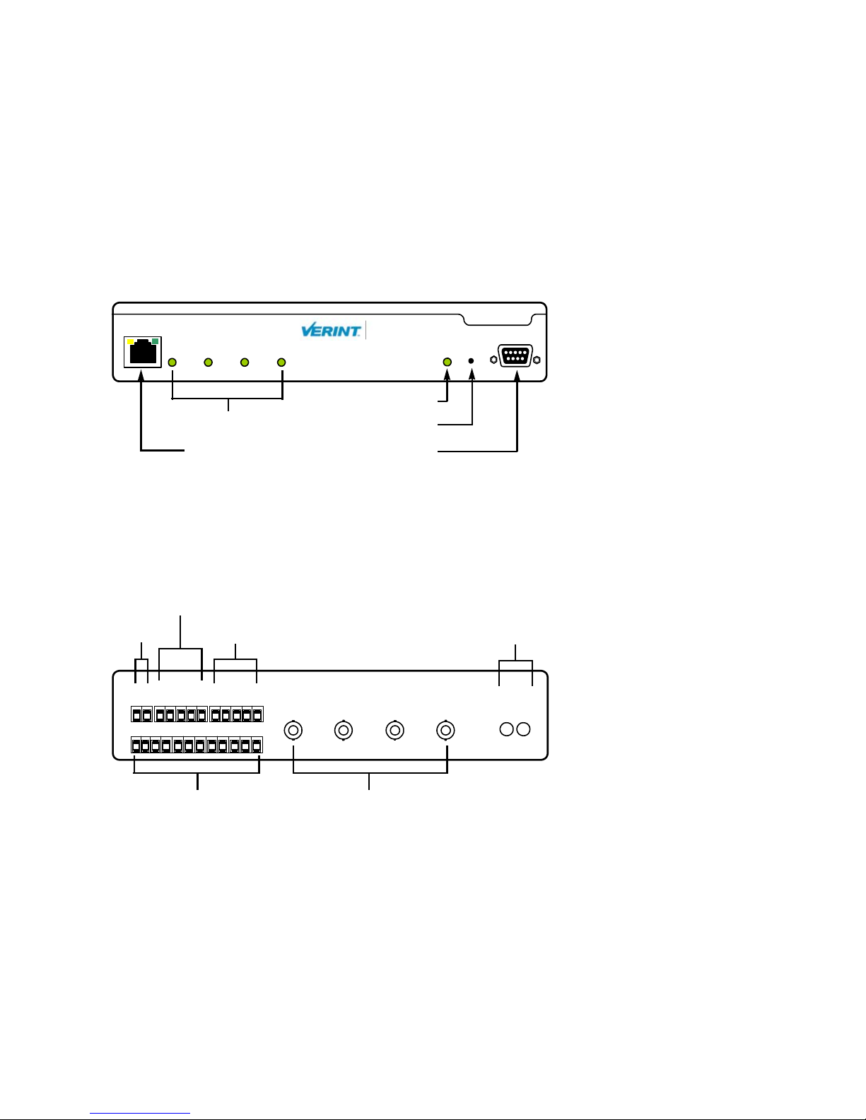
S1704e-AS
The front panel consists of:
An RJ-45 jack
Four video status LEDs
A system status LED
A reset button
A DB-9 connector for the RS-232 serial port
Nextiva Multiport S17XXe Series User Guide
LAN 10/100
1432
Video Status
Nextiva
TM
RS232
ResetStatus
System status
S1704e
Video status
RJ-45 Ethernet
Reset
RS-232
The back panel consists of:
A 12-pole connector for input power, relay outputs, and RS-422/485 serial port
A 12-pole connector for dry contact inputs
Four BNC connectors for video input
An optional set of 1/8 inch (3.5 mm) I/O audio connectors
Relay output
12V DC
GND
+12V
1
2
RS-422/485 Audio (optional)
RLY2
GND
365
4
RLY1
TX+
RLY1
RLY2
7
8
RX-
GND
TX-
RX+
IN1 IN2 IN3
9
11
12
10
VIDEO IN
IN4
AUDIO
IN
OUT
Dry contact input
Verint Video Solutions 5
Video input
1: Overview
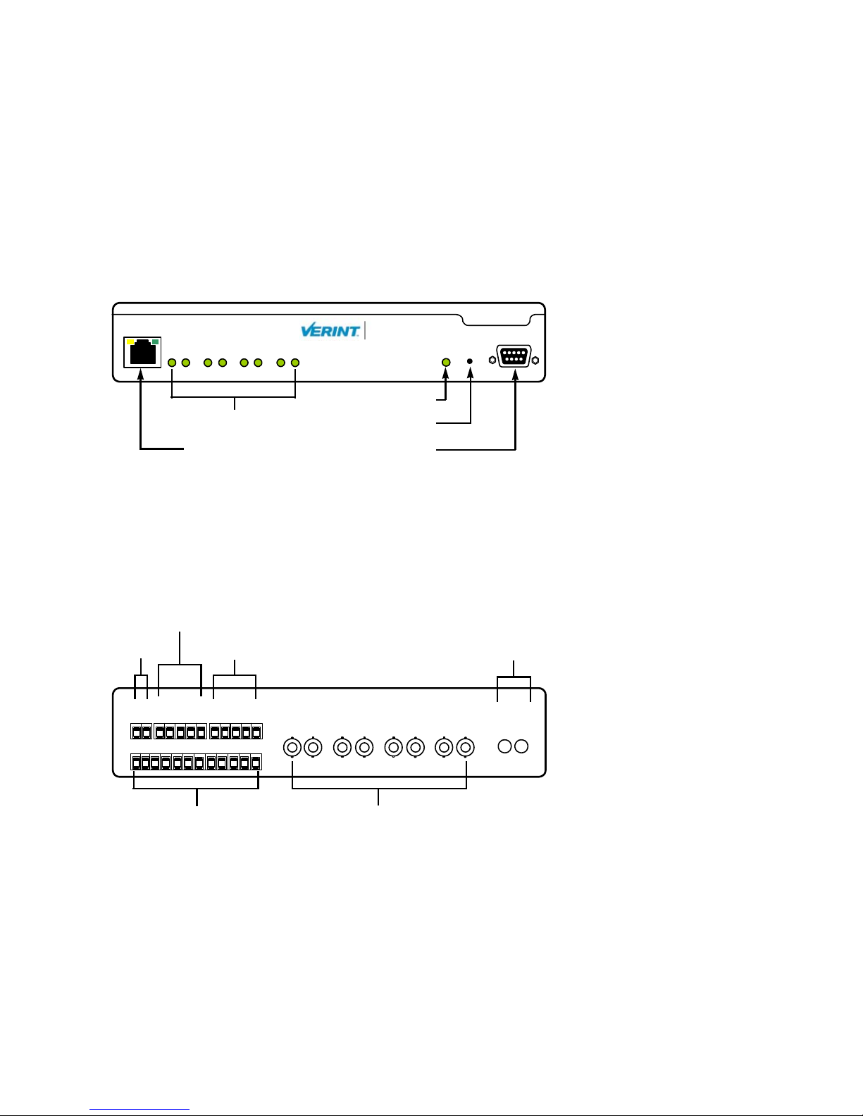
S1708e and S1708e-AS
The front panel consists of:
An RJ-45 jack
Eight video status LEDs
A system status LED
A reset button
A DB-9 connector for the RS-232 serial port
LAN 10/100
18765432
Video Status
Nextiva
TM
RS232
ResetStatus
System status
S1708e
Video status
RJ-45 Ethernet
Reset
RS-232
Two versions of the back panels exist, since the device can have 1 or 12 audio inputs. The
back panel of the single-audio-input version consists of:
A 12-pole connector for input power, relay outputs, and RS-422/485 serial port
A 12-pole connector for dry contact inputs
Eight BNC connectors for video input
An optional set of 1/8 inch (3.5 mm) I/O audio connectors
Relay output
12V DC
+12V
1
2
RS-422/485 Audio (optional)
GND
RLY2
GND
365
4
RLY1
TX+
RLY1
RLY2
7
8
RX-
GND
TX-
RX+
IN1 IN2 IN3 IN4 IN5 IN6
9
11
10
12
VIDEO IN
IN7
IN8
AUDIO
IN
OUT
Dry contact input
6 Verint Video Solutions
Video input
Nextiva Multiport S17XXe Series User Guide
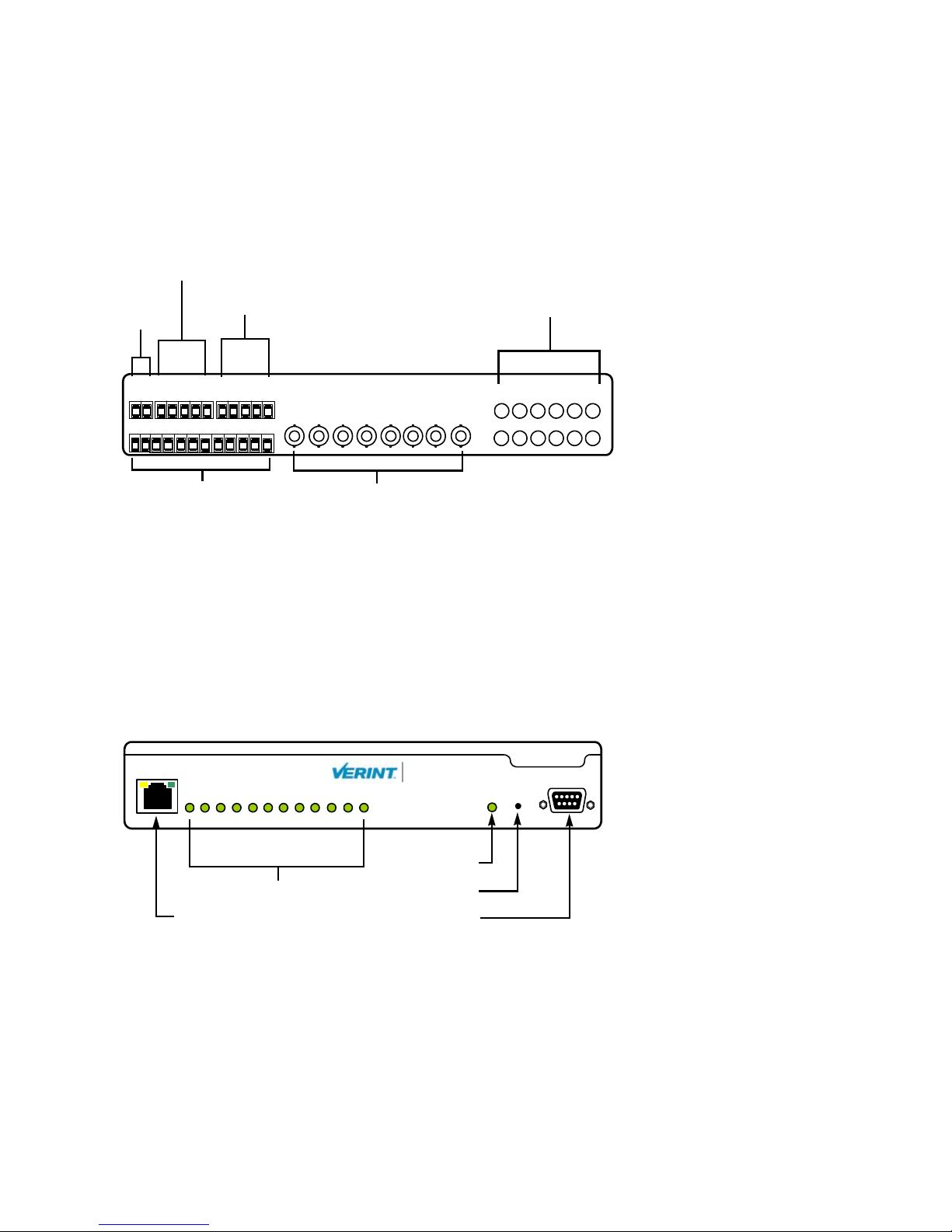
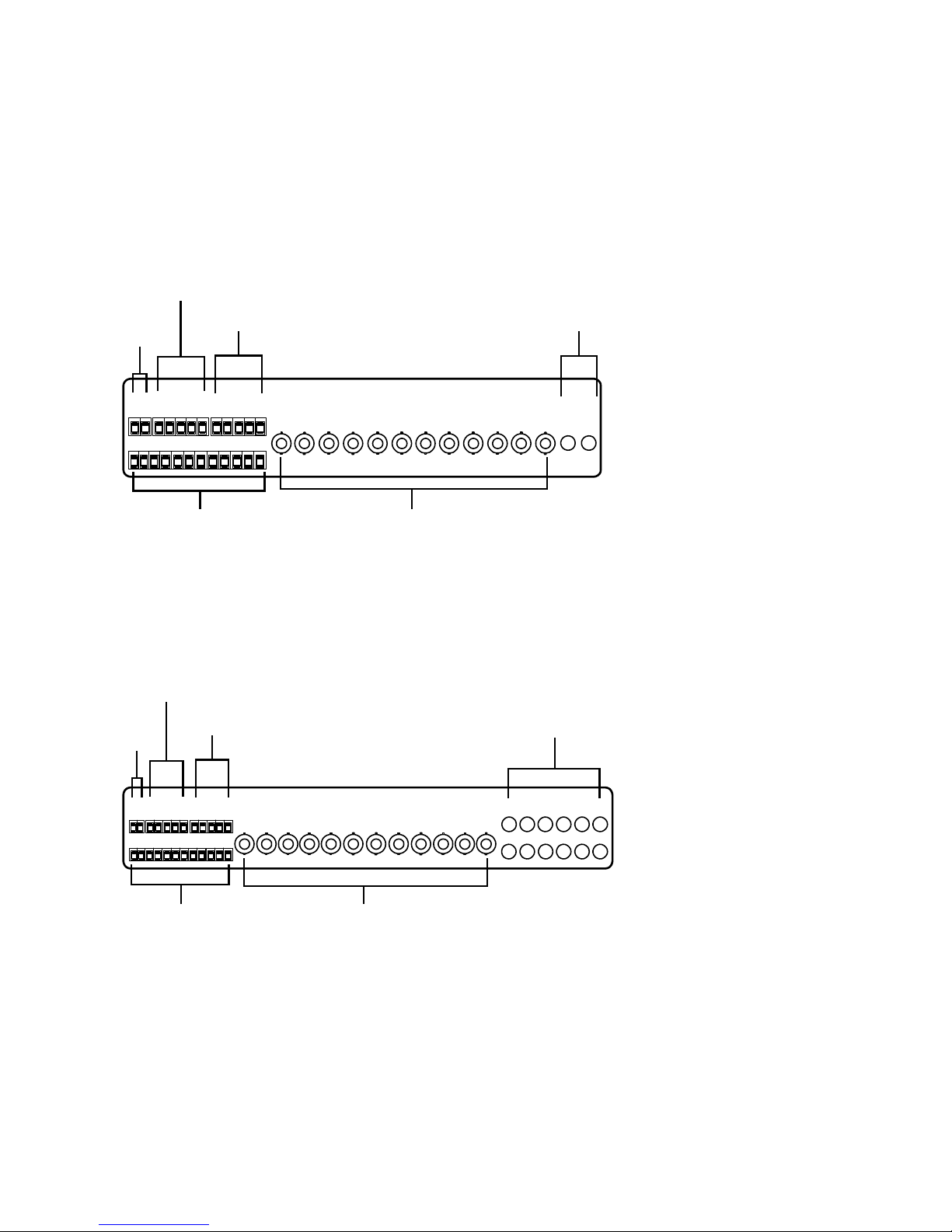
The back panel of the 12-audio-input version consists of:
A 12-pole connector for input power, relay outputs, and RS-422/485 serial port
A 12-pole connector for dry contact inputs
Eight BNC connectors for video input
Twelve 1/8 inch (3.5 mm) audio input connectors
Relay output
12V
RS-422/485 Audio input
DC
GND
+12V
GND
1
2
365
RLY1
TX+
RLY1
RLY2
RLY2
4
GND
TX-
RX+
7
8
9
11
10
Dry contact input
RX-
12
VIDEO IN
IN8IN7IN6IN5IN4IN3IN2IN1
Video input
S1712e
The front panel consists of:
An RJ-45 jack for Ethernet connection
Twelve video status LEDs
A system status LED
A reset button
A DB-9 connector for the RS-232 serial port
AUDIO IN
195
371211
8624
10
LAN 10/100
18765432
Video Status
Nextiva
9 11 1210
TM
RS232
ResetStatus
System
status
S1712e
Video status
RJ-45 Ethernet
Verint Video Solutions 7
Reset
RS-232
1: Overview
Two versions of the back panels exist, since the device can have 1 or 12 audio inputs. The
back panel of the single-audio-input version consists of:
A 12-pole connector for power, relay outputs, and RS-422/485 serial port
A 12-pole connector for dry contact inputs
Twelve BNC connectors for video input
An optional set of 1/8 inch (3.5 mm) I/O audio connectors
Relay output
12V
RS-422/485
Audio (optional)
DC
GND
+12V
1
2
36548
RLY1
TX+
RLY1
RLY2
RLY2
GND
7
RX-
GND
TX-
RX+
9
11
12
10
Dry contact input
VIDEO IN
IN2 IN3 IN4 IN5 IN6 IN7 IN8 IN9
Video input
IN10 IN11
IN12
AUDIO
IN
OUTIN1
The back panel of the 12-audio-input version consists of:
A 12-pole connector for input power, relay outputs, and RS-422/485 serial port
A 12-pole connector for dry contact inputs
Twelve BNC connectors for video input
Twelve 1/8 inch (3.5 mm) audio input connectors
Relay output
12V
RS-422/485 Audio input
DC
TX-
RX-
TX+
GND
GND
+12V
RLY2
RLY2
1
2
Dry contact input
RX+
GND
RLY1
RLY1
73654
8
9
12
11
10
Video input
8 Verint Video Solutions
VIDEO IN
AUDIO IN
195
IN9IN8IN7IN6IN5IN4IN3IN2IN1
IN11IN10
IN12
371211
8624
10

S1724e
The front panel consists of:
An RJ-45 jack
Twenty-four video status LEDs
A system status LED
A reset button
A DB-9 connector for the RS-232 serial port
Nextiva Multiport S17XXe Series User Guide
LAN 10/100
13 20191817161514 24232221
Video Status
18765432 9 11 1210
Nextiva
TM
S1724e
ResetStatus
RS232
System
Video status
RJ-45 Ethernet
status
Reset
RS-232
The back panel consists of:
A 12-pole connector for input power, relay outputs, and RS-422/485 serial port
A 12-pole connector for dry contact inputs
Twenty-four BNC connectors for video input
An optional set of 1/8 inch (3.5 mm) I/O audio connectors
Relay output
12V
RS-422/485
Audio (optional)
DC
+12V
1
GND
2
RLY1
TX-
TX+
GND
RLY1
RLY2
RLY2
73654
8
RX-
GND
RX+
IN13 IN24IN14 IN15 IN16 IN17 IN18 IN19 IN20 IN21 IN22 IN23
9
11
12
10
IN1 IN12IN2 IN3 IN4 IN5 IN6 IN7 IN8 IN9 IN10 IN11
AUDIO
IN
OUT
Dry contact input Video input
Verint Video Solutions 9
 Loading...