

Page 1

Nextiva S1700e Series
Installation Guide
Page 2

Page 3

Nextiva S1700e Series
Page 4

© 2005 Verint Systems Inc. All rights reserved.
By providing this document, Verint Systems Inc. is not making any
representations regarding the correctness or completeness of its
contents and reserves the right to alter this document at any time
without notice.
Verint, Actionable Intelligence, BehaviorTrack, Dellis, HealthCheck,
I-Rooms, Lanex, Loronix, Loronix Video Manager, MotionTrack,
microDVR, nDVR, netDVR, Nextiva, Powering Actionable Intelligence,
RP Security, Safe on the Move, SmartSight, Video Manager, and
Page 5

Contents
Preface ...................................................................................... v
Page 6

Contents
Index ....................................................................................... 25
Edge Device Description Form .................................................. 27
Page 7

Page 8

Preface
Who Should Read this Guide
This guide is intended for engineers and technicians who will install the
S1700e series edge devices. It provides basic information on how to
configure and install the devices.
This guide assumes that you are familiar with:
Installation and manipulation of electronic equipment
General use of computers
Page 9

Nextiva S1700e Series Installation Guide
In addition to this guide, the following documentation is also available:
Nextiva S1700e Series User Guide
SConfigurator User Guide
Release Notes
All these documents are contained on the SmartSight Utilities CD
shipped with the device.
Page 10

Preface
To request the latest versions of firmware and software or to download
other product-related documents, you need access to the Verint Video
Solutions partner extranet. To register, go to http://vvs.verint.com
.
Support
If you encounter any type of problem after reading this guide, contact
your local distributor or Verint Video Solutions representative. You can
also use the following sections on the Verint Video Solutions partner
extranet to find the answers to your questions:
Page 11

1
Page 12

1: Overview
About the S1700e Series
The S1700e series devices are for indoor use only.
Each device is configured to interface, right out of the box, with the most
popular camera data port configuration (4800 baud, 8 data bits, no
parity, 1 stop bit).
The S1700e series currently holds a single transmitter, the S1700e-T. It
offers the following features:
Page 13

Nextiva S1700e Series Installation Guide
Shipment
Your S1700e shipment contains the following items:
The requested transmitter device
Either a power-over-Ethernet kit (injector and power cord) or a
12V DC external power supply
The SmartSight Utilities CD containing the release notes and
documentation for the device as well as the SConfigurator application
Page 14

1: Overview
Casing Description
The S1700e electronics are enclosed in a non-weatherproof steel casing
that is not meant for outdoor use.
The front panel consists of:
An RJ-45 jack for PoE or the Ethernet network
A system status LED
Page 15

Nextiva S1700e Series Installation Guide
The back panel consists of:
A 12-pole connector for power, dry-contact inputs, relay outputs, and
RS-422/485
One BNC connector for video input
Optional audio connectors
A slot for an SD device (for future development)
12V DC
RS-422/485
Audio (optional)
Page 16

Page 17

2
Page 18

2: Configuration and Installation
Configuration
The configuration steps to execute are:
Assembling the power-over-Ethernet kit (on the PoE devices only)
Setting a series of parameters, including the IP address
Establishing a point-to-point connection between a receiver and a
transmitter, if required
Page 19

Nextiva S1700e Series Installation Guide
Assembling the PoE Kit
You use the supplied power-over-Ethernet (PoE) kit to power the
S1700e-PoE device and establish the Ethernet connection. The kit
contains two items: an injector and a power cord.
Warning: On a PoE device, never connect an external power supply in
the DC Pwr poles on its back.
Page 20

2: Configuration and Installation
To assemble the PoE kit:
2
3 4
5
J2
J1
Straight-through
Ethernet cable
Ethernet cable
Page 21

Nextiva S1700e Series Installation Guide
3. Plug the other end of the cable into the DATA & PWR port of the
injector.
4. Connect a second Ethernet cable (straight-through or crossover) into
the DATA port of the injector.
The crossover cable is to directly connect the device to a computer;
the straight-through cable is to integrate the S1700e on a network.
Note: The maximum length of this cable is 82 feet (25 meters).
5. Connect the other end of the second cable into an Ethernet device
Page 22

2: Configuration and Installation
Preparing a 12V DC Device
To prepare a 12V DC device for configuration:
1. In a lab, unpack the S1700e and place it on a table.
2. Establish the Ethernet connection by plugging a cable (crossover or
straight-through) into the LAN 10/100 connector on the front of the
device.
The crossover cable is to directly connect the device to a computer;
Page 23

Nextiva S1700e Series Installation Guide
Setting Device Parameters
The first step in installing an S1700e device is to change its IP address to
ensure compatibility with an existing network. Write down the IP
information in the form located at the end of the guide, on page 27.
To set the parameters of a device:
1. Ensure that the device has power and is connected to the network.
2. Start SConfigurator.
Page 24

2: Configuration and Installation
3. In the General tab, click Program Options.
The Program Options window appears.
Page 25

Nextiva S1700e Series Installation Guide
7. Select the Units tab, then click Discover.
Page 26

2: Configuration and Installation
8. Select the unknown device, then click Configure. In the Reconfigure
unit? confirmation window, click Yes.
The New Network Configuration window appears.
Page 27

Nextiva S1700e Series Installation Guide
11. In the Units tab, click Discover.
The new S1700e device appears.
12. Select the device, then click Configure.
13. Configure the serial port parameters to match those of the target
equipment (for instance, camera or PTZ keyboard).
For more information, refer to the SConfigurator User Guide.
The S1700e initial configuration is now complete.
Page 28

2: Configuration and Installation
To perform a point-to-point connection:
1. Start SConfigurator.
2. In the Units tab, discover the desired devices.
The discovered devices appear in the Units box.
3. Select the Connections tab, then click Add.
The Connection Creator window appears.
Page 29

Nextiva S1700e Series Installation Guide
4. Select a transmitter in the left column and a receiver in the right one.
In the Transmitters column, you have access to the two encoders of
each input; the video stream is the same for both. Stream1 is
typically reserved for web viewing, therefore you should use Stream2
for point-to-point connections.
5. In the Video list, select the desired video mode.
6. To disable I/O data transmission (for example, alarms) between the
two selected devices, clear Forward I/O.
Page 30

2: Configuration and Installation
Installation
When your device is successfully configured, it is ready to be installed in
its final location.
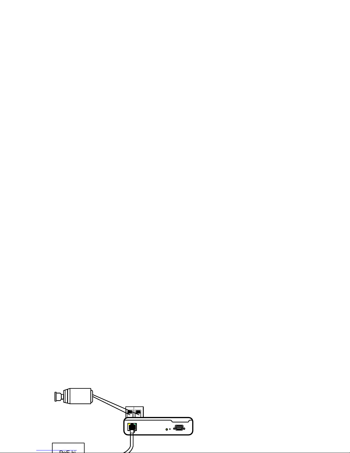
If your S1700e device is powered using PoE, you can use the two DC Pwr
poles on the back of the device to power a camera. The supply voltage of
the camera must be 12V DC +/- 10%; its maximum power consumption
must be 5W (417 mA).
Page 31
Nextiva S1700e Series Installation Guide
4. If required on a PoE device, connect the power wires of a camera to
the DC Pwr poles on the connector on the back of the device.
+12VGnd
Gnd +12V
Page 32

2: Configuration and Installation
6. When installing a device with the extended temperature option,
make it stand vertically, allowing for better cooling.
Page 33

Nextiva S1700e Series Installation Guide
Flashing green (1 sec.
intervals)
The firmware has started, the device is connected to
the network, but no video/audio/serial* data is
transmitted.
Flashing green (0.2 sec.
intervals)
The firmware has started, the device is connected to
the network, and video/audio/serial* data is
transmitted.
Three consecutive red
blinks every 2 sec.
No video source is detected and no video is
transmitted.
Flashing green-red (1 sec.
intervals)
The device is undergoing a firmware update.
Condition Indication
Page 34

2: Configuration and Installation
Flashing green-red LED not during a firmware update—The device is
in backup mode; you will need to perform a firmware update using a
serial connection.
Page 35

Index
A
abnormal power-up conditions 23
C
cable, Ethernet 10, 11
camera
data port configuration 2
E
enclosure of the device 4
equipment list 3
Ethernet cable 10
, 11
extranet, Verint Video Solutions viii
F
Page 36

Index
P
panel of device 4
PoE (power-over-Ethernet)
injector 9
–11
point-to-point connection 17
power connection 9
–11, 12
power requirements 2
power supply 9
power-up conditions 23
R
requirements
V
Verint Video Solutions web site vii
W
web site, Verint Video Solutions vii
Page 37

Page 38

Edge Device Description Form
During configuration, write down the following settings that may be
required by Verint Video Solutions customer service for troubleshooting:
System Firmware version
VSIP VSIP port
Video Bit rate
Frame rate
Page 39

 Loading...