


Nextiva HDR 1800 v1.0
User Guide
November 2010

Coyright Notice
© 2010 Verint Systems Inc. All Rights Reserved Worldwide. www.verint.com/videosolutions
Unauthorized use, duplication, or modification of this document in whole or in part without the written consent of Verint Systems Inc. is
strictly prohibited. By providing this document, Verint Systems Inc. is not making any representations regarding the correctness or
completeness of its contents and reserves the right to alter this document at any time without notice. Features listed in this document are
subject to change.
Verint Systems Inc. does not warrant, guarantee or make any representation regarding the use or the results of the use of the information,
links, tools, and materials in terms of the accuracy, reliability, quality, validity, stability, completeness, currentness, or otherwise of its
content or products. The entire risk as to the use, results and performance of information, links, tools and materials provided or referenced
herein is assumed by the user. Verint Systems Inc. shall not be liable for damages resulting from the use, misuse or unlawful use of the
information, links, tools, and materials contained or referenced herein.
The Verint Systems Inc. products are protected by one or more of the following U.S., European or International Patents: USPN 5,659,768;
USPN 5,689,442; USPN 5,790,798; USPN 6,278,978; USPN 6,370,574; USPN 6,404,857; USPN 6,510,220; USPN 6,724,887; USPN
6,751,297; USPN 6,757,361; USPN 6,782,093; USPN 6,839,667; USPN 6,952,732; USPN 6,959,078; USPN 6,959,405; USPN 7,047,296;
USPN 7,149,788; USPN 7,155,399; USPN 7,203,285; USPN 7,216,162; USPN 7,219,138; USPN 7,254,546; USPN 7,281,173; USPN
7,284,049; USPN 7,325,190; USPN 7,466,816; USPN 7,478,051; USPN RE40,634; and other provisional rights from one or more of the
following Published US Patent Applications: US 11/394,408; US 11/771,499; US 11/396,514; US 11/772,440; US 11/565,943; US 11/
565,946; US 11/565,948; US 11/540,739; US 11/540,086; US 11/541,313; US 11/541,252; US 11/540,282; US 11/529,947; US 11/
540,785; US 11/540,736; US 11/540,904; US 11/540,353; US 11/608,340; US 11/608,350; US 11/608,358; US 11/567,808; US 11/
692,983; US 11/693,933; US 11/693,923; US 11/693,828; US 11/567,852; US 11/608,440; US 12/015,621; US 11/540,322; US 11/
924,201; US 11/616,490; US 11/621,134; US 11/752,458; US 11/712,933; US 11/824,980; US 11/729,185; US 11/804,748; US 11/
831,260; US 11/395,992; US 11/359,319; US 11/359,195; US 11/359,357; US 10/832,509; US 11/742,733; US 11/831,257; US 11/
831,250; US 11/691,530; US 11/479,267; US 11/529,942; US 11/768,349; US 11/540,281; US 10/633,357; US 11/693,899; US 11/
479,056; US 11/529,132; US 11/540,320; US 11/037,604; US 11/529,842; US 11/540,171; US 11/478,714; US 11/529,946; US 11/
868,656; US 11/776,659; US 11/090,638; US 11/410,004; US 10/771,315; US 10/771,409; US 11/540,900; US 11/528,267; US 12/
118,781; and other U.S. and International Patents and Patents Pending.
VERINT, the VERINT logo, ACTIONABLE INTELLIGENCE, POWERING ACTIONABLE INTELLIGENCE, WITNESS ACTIONABLE
SOLUTIONS, STAR-GATE, RELIANT, VANTAGE, X-TRACT, NEXTIVA, ULTRA, AUDIOLOG, WITNESS, the WITNESS logo, IMPACT
360, the IMPACT 360 logo, IMPROVE EVERYTHING, EQUALITY, CONTACTSTORE, and CLICK2STAFF are trademarks or registered
trademarks of Verint Systems Inc. or its subsidiaries. Other trademarks mentioned are the property of their respective owners.
Compliance
United States Statement for FCC
These equipments has been tested and found to comply with the limits for a Class A digital device, pursuant to Part 15 of the FCC Rules.
These limits are designed to provide reasonable protection against harmful interference when the equipment is operated in a commercial
environment. This equipment generates, uses, and can radiate radio frequency energy and, if not installed and used in accordance with
the instruction manual, may cause harmful interference to radio communications. Operation of this equipment in a residential area is likely
to cause harmful interference in which case the user will be required to correct the interference at his own expense.
Industry Canada Statement
This Class A digital apparatus complies with Canadian ICES-003.
Cet appareil numérique de la classe A est conforme à la norme NMB-003 du Canada.
Europe EN 55022 Statement
This is to certify that the Nextiva S1808e and S1816e Ethernet video servers are shielded against the generation of radio interference
in accordance with the application of Council Directive 2004/108/EC. Conformity is declared by the application of EN55022 Class
A (CISPR 22).
RoHS Declaration of Compliance
Verint believes in the importance of conducting our business in a manner that will help protect the environment as well
as our employees, customers and the public. To that end, we are committed to bringing our existing and future product
lines into EU RoHS Directive compliance.
Thus, the S1808e and S1816e Ethernet video servers are compliant with the DIRECTIVE 2002/95/EC OF THE
of certain hazardous substances in electrical and electronic equipment.
The S1808e and S1816e products will not exceed the maximum concentrations of 0.1% by weight in homogenous materials for Lead (Pb),
Hexavalent chromium (Cr6+), Mercury (Hg), Polybrominated biphenyls (PBB), Polybrominated diphenyl ether (PBDE), and 0.01% for
Cadmium (Cd). In addition, the S1808e and S1816e products will qualify for the “lead in servers solders” exemption as set forth in the
Directive.
This declaration is provided based on reasonable inquiry of our suppliers and represents our actual knowledge based on the information
provided by our suppliers.
EUROPEAN PARLIAMENT AND OF THE COUNCIL of 27 January 2003 (RoHS) regarding the restriction of the use
WEEE Directive
The European Union has enacted a Directive 2002/96/EC on Waste Electrical and Electronic Equipment (WEEE Directive). This
directive is applicable in the European Union member states.
The WEEE marking on this product or its documentation indicates that the product must not be disposed of together with
household waste. To prevent possible harm to human health and/or the environment, the product must be disposed of in an
approved and environmentally safe recycling process. For further information on how to dispose of this product correctly, contact
supplier for information on how to dispose of this product correctly. This product should not be mixed with other commercial waste.
the product supplier, or the local authority responsible for waste disposal in your area. Business users should contact the product

Contents
Safety . . . . . . . . . . . . . . . . . . . . . . . . . . . . . . . . . . . . . . . . . . . . . . . . . . . . . iii
Preface . . . . . . . . . . . . . . . . . . . . . . . . . . . . . . . . . . . . . . . . . . . . . . . . . . . . v
Audience . . . . . . . . . . . . . . . . . . . . . . . . . . . . . . . . . . . . . . . . . . . . . . . . . . . . . . . . . . . v
Contacting Verint . . . . . . . . . . . . . . . . . . . . . . . . . . . . . . . . . . . . . . . . . . . . . . . . . . . . v
Contacting Service and Support . . . . . . . . . . . . . . . . . . . . . . . . . . . . . . . . . . . . . . . . .vi
Related Documentation . . . . . . . . . . . . . . . . . . . . . . . . . . . . . . . . . . . . . . . . . . . . . . .vi
Summary of Changes . . . . . . . . . . . . . . . . . . . . . . . . . . . . . . . . . . . . . . . .vii
Revision 2 — October 2010 . . . . . . . . . . . . . . . . . . . . . . . . . . . . . . . . . . . . . . . . . . . vii
Revision 1 — April 2010 . . . . . . . . . . . . . . . . . . . . . . . . . . . . . . . . . . . . . . . . . . . . . . vii
Features . . . . . . . . . . . . . . . . . . . . . . . . . . . . . . . . . . . . . . . . . . . . . . . . . . . . . . . . vii
Chapter 1: Overview of the HDR 1800 . . . . . . . . . . . . . . . . . . . . . . . . . . . 1
Hardware Overview . . . . . . . . . . . . . . . . . . . . . . . . . . . . . . . . . . . . . . . . . . . . . . . . . . 2
Product Dimensions and Weight . . . . . . . . . . . . . . . . . . . . . . . . . . . . . . . . . . . . . . 3
Monitor Configuration . . . . . . . . . . . . . . . . . . . . . . . . . . . . . . . . . . . . . . . . . . . . . . . . . 4
Frame Rate and Performance . . . . . . . . . . . . . . . . . . . . . . . . . . . . . . . . . . . . . . . . . . 5
Chapter 2: Installing the HDR 1800 . . . . . . . . . . . . . . . . . . . . . . . . . . . . . . 7
Package Contents . . . . . . . . . . . . . . . . . . . . . . . . . . . . . . . . . . . . . . . . . . . . . . . . . . . 8
Installing the HDR 1800 . . . . . . . . . . . . . . . . . . . . . . . . . . . . . . . . . . . . . . . . . . . . . . . 9
Connecting the HDR 1800 . . . . . . . . . . . . . . . . . . . . . . . . . . . . . . . . . . . . . . . . . . . . 11
Connecting the Network and Power Cables . . . . . . . . . . . . . . . . . . . . . . . . . . . . . 11
Connecting Monitors . . . . . . . . . . . . . . . . . . . . . . . . . . . . . . . . . . . . . . . . . . . . . . 12
Connecting a CCTV Keyboard . . . . . . . . . . . . . . . . . . . . . . . . . . . . . . . . . . . . . . . 13
Powering On the HDR 1800 . . . . . . . . . . . . . . . . . . . . . . . . . . . . . . . . . . . . . . . . . . . 14
Verint Video Intelligence Solutions
i

Contents
Chapter 3: Configuring the HDR 1800 . . . . . . . . . . . . . . . . . . . . . . . . . . . 15
Getting Started . . . . . . . . . . . . . . . . . . . . . . . . . . . . . . . . . . . . . . . . . . . . . . . . . . . . .16
Discovering the HDR 1800 . . . . . . . . . . . . . . . . . . . . . . . . . . . . . . . . . . . . . . . . . . . .17
Configuring Network Settings . . . . . . . . . . . . . . . . . . . . . . . . . . . . . . . . . . . . . . . . . .20
Configuring Monitor Output Settings . . . . . . . . . . . . . . . . . . . . . . . . . . . . . . . . . . . . . 22
Registering the HDR 1800 with Nextiva VMS . . . . . . . . . . . . . . . . . . . . . . . . . . . . . . 25
Adding the HDR 1800 to Physical and Logical Groups . . . . . . . . . . . . . . . . . . . . . .27
Viewing and Configuring Physical Settings . . . . . . . . . . . . . . . . . . . . . . . . . . . . . . . . 29
Viewing General Properties . . . . . . . . . . . . . . . . . . . . . . . . . . . . . . . . . . . . . . . . .30
Viewing Network Settings . . . . . . . . . . . . . . . . . . . . . . . . . . . . . . . . . . . . . . . . . . .31
Setting Audio Output . . . . . . . . . . . . . . . . . . . . . . . . . . . . . . . . . . . . . . . . . . . . . . . 32
Setting Aspect Ratio . . . . . . . . . . . . . . . . . . . . . . . . . . . . . . . . . . . . . . . . . . . . . . . 33
Configuring Serial Ports . . . . . . . . . . . . . . . . . . . . . . . . . . . . . . . . . . . . . . . . . . . . 34
Updating the Firmware . . . . . . . . . . . . . . . . . . . . . . . . . . . . . . . . . . . . . . . . . . . . .36
Configuring the HDR 1800 in Virtual Matrix . . . . . . . . . . . . . . . . . . . . . . . . . . . . . . .37
Assigning Monitor IDs . . . . . . . . . . . . . . . . . . . . . . . . . . . . . . . . . . . . . . . . . . . . . . 37
Assigning Startup Video Sources to Monitors . . . . . . . . . . . . . . . . . . . . . . . . . . . . 39
Adding a CCTV Keyboard . . . . . . . . . . . . . . . . . . . . . . . . . . . . . . . . . . . . . . . . . .40
Customizing On-screen Display . . . . . . . . . . . . . . . . . . . . . . . . . . . . . . . . . . . . . .42
Resetting the HDR 1800 to Partially Discovered State . . . . . . . . . . . . . . . . . . . . . . .43
Restoring Factory Default Settings . . . . . . . . . . . . . . . . . . . . . . . . . . . . . . . . . . . . . .46
Appendix A: Specifications and Configuration . . . . . . . . . . . . . . . . . . . . . 49
Technical Specifications . . . . . . . . . . . . . . . . . . . . . . . . . . . . . . . . . . . . . . . . . . . . . . 50
Factory Default Configuration . . . . . . . . . . . . . . . . . . . . . . . . . . . . . . . . . . . . . . . . . .52
Glossary . . . . . . . . . . . . . . . . . . . . . . . . . . . . . . . . . . . . . . . . . . . . . . . . . . 53
Index . . . . . . . . . . . . . . . . . . . . . . . . . . . . . . . . . . . . . . . . . . . . . . . . . . . . 57
www.verint.com/video_solutions
ii

Safety
Always observe the following precautions to reduce the risk of injury and equipment damage:
The Nextiva HDR 1800 is for indoor use only.
The Nextiva HDR 1800 should be placed on a secure flat surface or mounted using optional
hardware.
The Nextiva HDR 1800 should only be operated in a clean, dry environment.
The operating temperature is 32 to 104°F (0 to 40°C), with maximum humidity at 0 to 95%
relative, non-condensing at 104°F (40°C).
Only use the recommend power cable for powering the Nextiva HDR 1800.
Do not install the Nextiva HDR 1800 in an enclosed cabinet or other small area without
ventilation.
Verint Video Intelligence Solutions
iii


Preface
The Nextiva® High Definition Receiver (HDRTM) 1800 User Guide presents information and
procedures on installing, configuring, and using the HDR 1800.
Audience
This guide has been prepared for the following audience:
Managers
IT system administrators
Engineers
Technicians
Contacting Verint
Verint® Systems is a leading provider of Actionable Intelligence® solutions for enterprise
workforce optimization and security intelligence. Our solutions help government and enterprises
make sense of the vast information they collect in order to achieve their performance and security
goals. Today our solutions are used by more than 10,000 organizations in 150 countries. Verint is
headquartered in Melville, New York, with offices worldwide and 2500 dedicated professionals
around the globe. You can read about Verint Video Solutions and get marketing material and
product information at www.verint.com/videosolutions
To contact us for sales, pricing and general inquiries:
The Americas:
Email: videoinfo@verint.com
Telephone: +1 866-639-8482 for Nextiva VMS and Nextiva Intelligent Edge Devices
Telephone: +1-800-638-5969 for Nextiva embedded DVRs
Europe, the Middle East, or Africa:
Email: marketing.emea@verint.com
Telephone: +44 (0) 1932 839500
Asia Pacific:
Email: marketing.apac@verint.com
Telephone: + 852 2797 5678
.
Verint Video Intelligence Solutions
v
Contacting Service and Support
Contacting Service and Support
To request the latest versions of firmware and software or to download other product-related
documents, you need access to the Verint Video Intelligence Solutions partner extranet. To
register, go to https://ve5.verint.com
If you encounter any type of problem after reading this guide, contact your local distributor or Verint
representative. For the main service and support page on the Verint web page, visit
www.verint.com/videoservice
. For assistance, use our online web form at http://verint.com/
video_solutions/info/57008 or contact the customer service team:
Location Telephone E-mail Opening Hours
.
USA and
Canada
Central and
Latin America
Europe,
Middle East,
and Africa
Asia/Pacific Hong Kong: +852 2797
1-888-747-6246 vissupport@verint.com 8:00 am to 8:00
+1-303-254-7005 vissupport@verint.com
+44 (0) 845-843-7333 customersupport.emea@verint.com8:30 am to 5:30
+49 (0) 4321-269 81 36 mobilesupport@verint.com
(Transit applications only)
APAC_VIS_Services@verint.com 9:00 am to 6:30
5678
Singapore: +65-68266099
Related Documentation
The following documentations contain related information:
pm (EST) Monday
to Friday
pm (GMT) Monday
to Friday
pm
(Monday to
Thursday);
9:00 am to 5:30
pm (Friday)
Nextiva HDR 1800 Quick Install Guide
Nextiva Administrator Guide, version 6.1
Nextiva Third-Party PTZ Camera and CCTV Keyboard Integration Guide, version 6.1
Download the documentation at www.verint.com/manuals
extranet: https://ve5.verint.com
Send your questions or comments on the current document, or any other Nextiva user
documentation, to our documentation feedback team at documentationfeedback@verint.com.
vi
www.verint.com/video_solutions
. Download the latest firmware from the
.

Summary of Changes
This section lists technical updates and new material added to the Nextiva HDR 1800 User Guide.
Revision 2 — October 2010
This is the second edition of the Nextiva HDR 1800 User Guide.
Revision 1 — April 2010
This is the first edition of the Nextiva HDR 1800 User Guide.
Features
High-definition video decoder/receiver for use with Nextiva Virtual Matrix
H.264/MPEG-4/MJPEG video decoding at up to 1920x1080 screen resolution
Includes three video outputs: DVI, VGA (RGB), and BNC (Composite)
Fully configurable in Nextiva VMS 6.1, including full integration with Nextiva S1800e
encoders and Nextiva S5000 IP cameras with H.264 video compression technology.
Supports all third-party cameras and CCTV Keyboards supported by Nextiva VMS
Includes two serial ports: RS-232 and RS-422
Verint Video Intelligence Solutions
vii


Chapter
Overview of the HDR 1800
The Nextiva® High Definition Receiver (HDRTM) 1800 is a powerful enterprise-class, H.264
enabled video decoder/receiver designed for large-scale, geographically distributed
TM
operations. The HDR
and H.264 video decompression to enhance the functionality and versatility of Nextiva
Virtual Matrix implementations.
The following topics are discussed:
Hardware Overview . . . . . . . . . . . . . . . . . . . . . . . . . . . . . . . . . . . . . . . . . . . . . . . . . . . . . .2
Monitor Configuration . . . . . . . . . . . . . . . . . . . . . . . . . . . . . . . . . . . . . . . . . . . . . . . . . . . .4
Frame Rate and Performance . . . . . . . . . . . . . . . . . . . . . . . . . . . . . . . . . . . . . . . . . . . . . .5
1800 combine excellent performance, high-defnition technology,
Hardware Overview
Hardware Overview
The HDR 1800 integrates seamlessly with Nextiva Virtual Matrix, which routes video to computers,
video walls, and monitors across local and wide area networks (LANs/WANs). With Nextiva Virtual
Matrix, authorized personnel can view live and recorded high-definition video on digital monitors,
create custom video walls, control PTZ cameras, assign cameras to monitors on demand, and
replay alarm-based video at multiple locations simultaneously.
The HDR 1800 is ideal for video surveillance applications that call for high-defnition video to be
displayed at multiple locations for building situational awareness and a coordinated response.
Compatible with today's advanced video technologies, the HDR 1800 offers the fexibility to
decode compression formats from H.264 to MPEG-4 to MJPEG and use a wide range of monitors
including DVI, VGA, and traditional CCTV monitors.
The HDR 1800 is also fully integrated with Nextiva Video Management System (VMS) and Nextiva
intelligent edge devices, including the state-of-the-art S1800e encoders and S5000 high-definition
IP cameras with H.264 video compression technology. In addition, the HDR 1800 supports all
third-party cameras and CCTV Keyboards supported by Nextiva VMS.
The HDR 1800 includes the following components:
One Power/Status LED
Power button
19V DC +/-5% power receptacle
One BNC connector for composite video (NTSC/PAL)
One Digital DVI-D connector (with HDMI support using an HDMI male to DVI male connector
- not provided)
One VGA (RGB) connector
One RS-232 (DB9) serial port for CCTV keyboard connection
One RS-422 (DB9) serial port for CCTV keyboard connection
Two RJ-45 (Ethernet 10/100/1000 Base-T) network connectors
Four USB 2.0 ports
One Line-out, 1/8in (3.5mm) stereo jack for connecting external audio equipment
One Mic-in, 1/8in (3.5mm) stereo jack
CAUTION: The Nextiva HDR 1800 is enclosed in a non-weatherproof casing and should be
placed in a location that is not exposed to the outdoor environment.
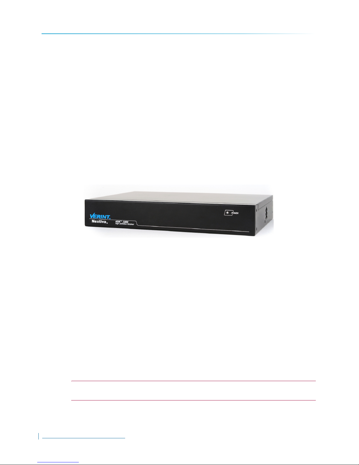
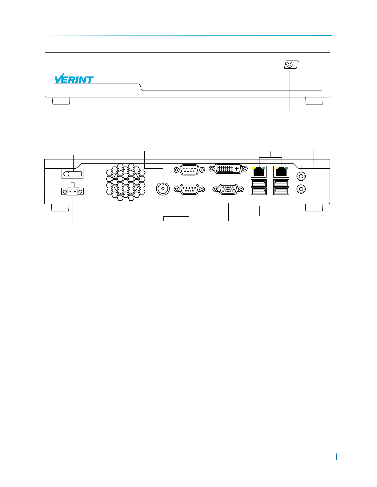
For the HDR 1800, the following two figures represent the front and rear views of the unit.
www.verint.com/video_solutions
2
Overview of the HDR 1800
POWER
HDR 1800
High-Definition Receiver
Nextiva
Power LED
GND
+19V DC
POWER
TV-OUT
COM2
(RS-422)
COM1
(RS-232)
DVI-D
VGA
LAN1
USB1-2
LAN2
USB3-4
LINE-OUT
MIC-IN
19V DC +/-5% power receptacle
RS-232 Input
USB Ports
Power
button
RS-422 Input
Network
Connectors (RJ-45)
VGA Connector
BNC Connector
Line-out
Mic-in
DVI-D
Connector
Figure 1.1: HDR 1800 Front View
Figure 1.2: HDR 1800 Rear View
Chapter 1
Product Dimensions and Weight
The HDR 1800 has the following dimensions:
11W × 7.5D × 1.7H in. (280W × 190D × 44H mm)
5.7lb (2.6Kg)
Verint Video Intelligence Solutions
3
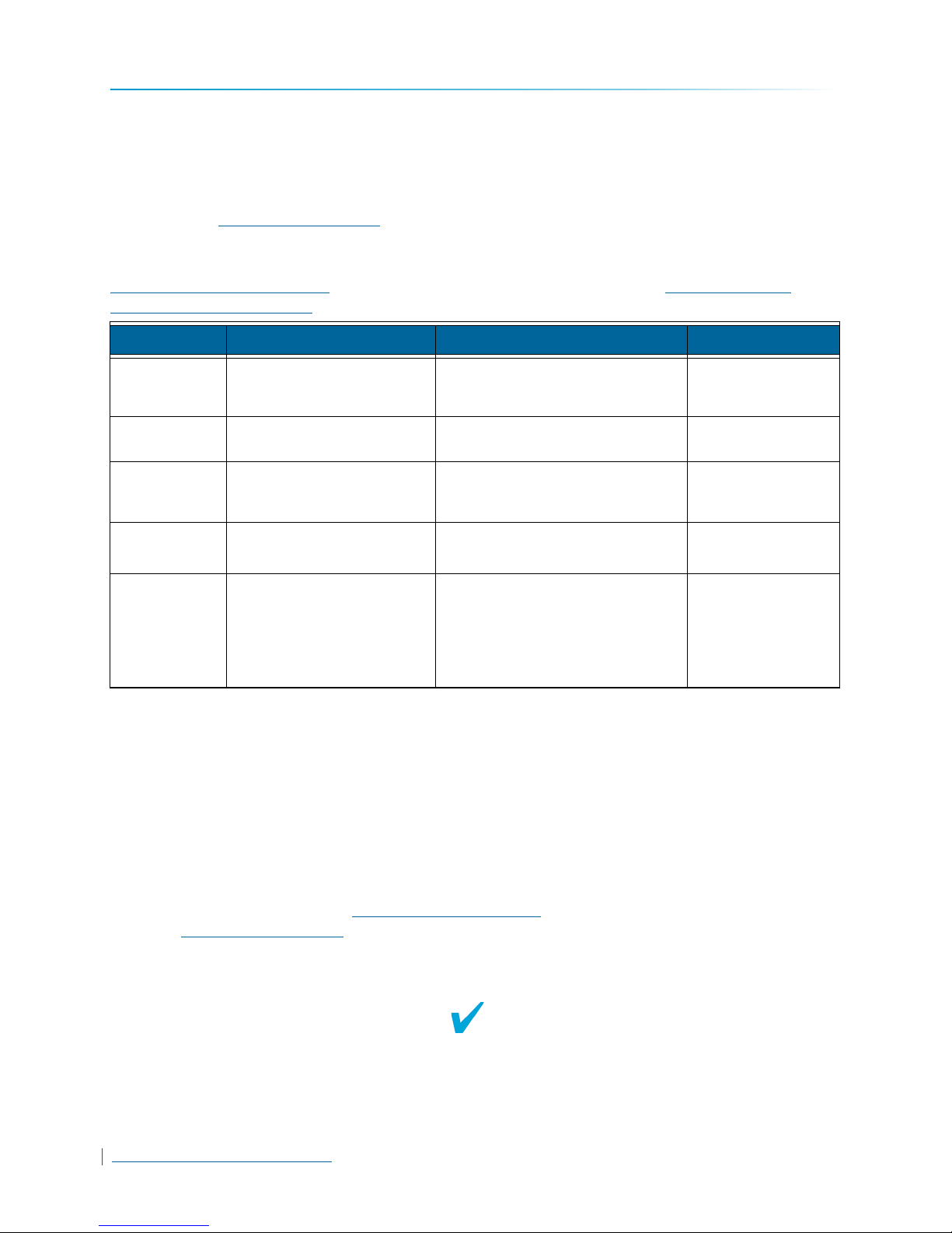
Monitor Configuration
Monitor Configuration
You can connect either one monitor (Single monitor configuration) or two monitors (Dual monitor
configuration) to the HDR 1800. In a Dual monitor configuration, the first monitor in the
configuration must be connected to the DVI-D connector on the HDR 1800; the second monitor
can be connected to either the VGA or BNC connectors.
NOTE: In the Dual monitor configuration, the total number of video tiles on both monitors
cannot exceed 18 tiles.
The following table lists the monitor configuration settings for the HDR 1800.
Connector Type
Single Monitor DVI-D
VGA
BNC
Dual Monitor:
Monitor 1 DVI-D 1x1 (1 tile)
Monitor 2 VGA or BNC
a.For DVI and VGA monitors, the HDR 1800 automatically adjusts the screen resolution to the best
available setting on the monitor (up to a maximum of 1920x1200).
Tile Layout
Options
1x1 (1 tile)
2x2 (4 tiles)
3x2 (6 tiles)
3x3 (9 tiles)
4x3 (12 tiles)
4x4 (16 tiles)
2x2 (4 tiles)
3x2 (6 tiles)
3x3 (9 tiles)
4x3 (12 tiles)
4x4 (16 tiles)
Maximum Screen
Resolution
DVI-D: Up to 1920x1200
VGA: Up to 1920x1200
BNC: 480/576 lines (NTSC/PAL)
DVI-D: Up to 1920x1200
VGA: Up to 1920x1200
BNC: 480/576 lines (NTSC/PAL)
a
www.verint.com/video_solutions
4

Chapter 1
Overview of the HDR 1800
Frame Rate and Performance
The HDR 1800 supports H.264, MPEG-4, MJPEG video decoding at up to 1920x1080 screen
resolution. In general, the performance for displaying video on monitors varies depending on the
tile layout, screen resolution, compression mode, and bitrate. The following table lists
performance values for the maximum frame rate:
NOTE: The performance values listed below are provided for reference only.
Compression Mode
Tile Layout MPEG-4 H.264
1 tile 1920×1080 at 30 fps 1920×1080 at 30 fps
6 tiles 4CIF at 30 fps 4CIF at 30 fps
9 tiles 4CIF at 30 fps 2CIF at 30 fps
16 tiles 2CIF at 30 fps CIF at 30 fps
18 tiles CIF at 30 fps CIF at 15 fps
Verint Video Intelligence Solutions
5


Chapter
Installing the HDR 1800
This chapter focuses on the physical installation of the HDR 1800. Network and other
physical settings for the HDR 1800 are configured in Nextiva Video Management System
(VMS); for more information, see Chapter 3, “Configuring the HDR 1800”.
The following topics are discussed:
Package Contents . . . . . . . . . . . . . . . . . . . . . . . . . . . . . . . . . . . . . . . . . . . . . . . . . . . . . . .8
Installing the HDR 1800. . . . . . . . . . . . . . . . . . . . . . . . . . . . . . . . . . . . . . . . . . . . . . . . . . .9
Connecting the HDR 1800. . . . . . . . . . . . . . . . . . . . . . . . . . . . . . . . . . . . . . . . . . . . . . . .11
Powering On the HDR 1800 . . . . . . . . . . . . . . . . . . . . . . . . . . . . . . . . . . . . . . . . . . . . . .14

Package Contents
Package Contents
CAUTION: The HDR 1800 is enclosed in a non-weatherproof steel casing and should only be
placed in an indoor environment.
Each installation kit comes with the following:
One HDR 1800 featuring H.264 technology
One set of rack-mount brackets
One set of wall-mount brackets
Six screws (Philips M4 × 6mm pan head)
Four bumpons
One AC100-240V 90W/+19V power adaptor
One Nextiva HDR 1800 Quick Installation Guide
www.verint.com/video_solutions
8
Chapter 2
Installing the HDR 1800
Installing the HDR 1800
This section explains how to install an HDR 1800. To ensure that the HDR 1800 functions properly,
consider the following:
Verify the outlet where you will connect the HDR 1800 for proper polarity. Use a standard
outlet only.
Use a surge protection device to minimize the risk of damage to the HDR 1800 in surge-
prone environments.
Do not install the HDR 1800 in an enclosed cabinet or other small, unventilated area. The
HDR 1800 can be mounted above other devices, as long as there is adequate ventilation
surrounding the rack.
Verify the dimensions of the shelf or surface to ensure that the HDR 1800 fits. The HDR
1800 is 11 inches wide by 7.5 inches deep by 1.7 inches high (280mm
NOTE: This equipment must be used in compliance with local laws and regulations.
The following installation options are available:
Installing the HDR 1800 on a desktop or flat surface (see page 9)
× 190mm × 44mm).
Installing the HDR 1800 on a rack (see page 9)
Mounting the HDR 1800 on a wall (see page 9)
To install the HDR 1800 on a flat surface:
1. Remove any debris and dust from the surface as well as the surrounding area.
2. Attach the four bumpons (provided) to each corner of the HDR 1800 using the provided
screws.
3. Place the unit on the flat surface.
4. Ensure that you have access to both the front and rear of the unit and that the fan airflow is
not blocked.
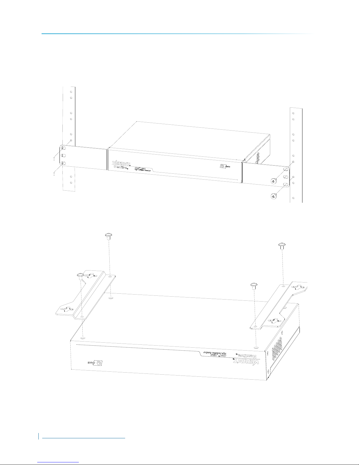
To install the HDR 1800 on a rack:
1. Align the rack- mount brackets with the holes on the side of the HDR 1800.
Verint Video Intelligence Solutions
9
Installing the HDR 1800
2. Screw the rack-mount brackets to the HDR 1800 using 12 in-lb (1.35 N-m) force with 6
screws (provided).
3. Slide the unit into the 1U mounting space in the rack cabinet and ensure that the fan airflow
is not blocked.
4. Secure the unit to the rack cabinet using the screws supplied with the rack.
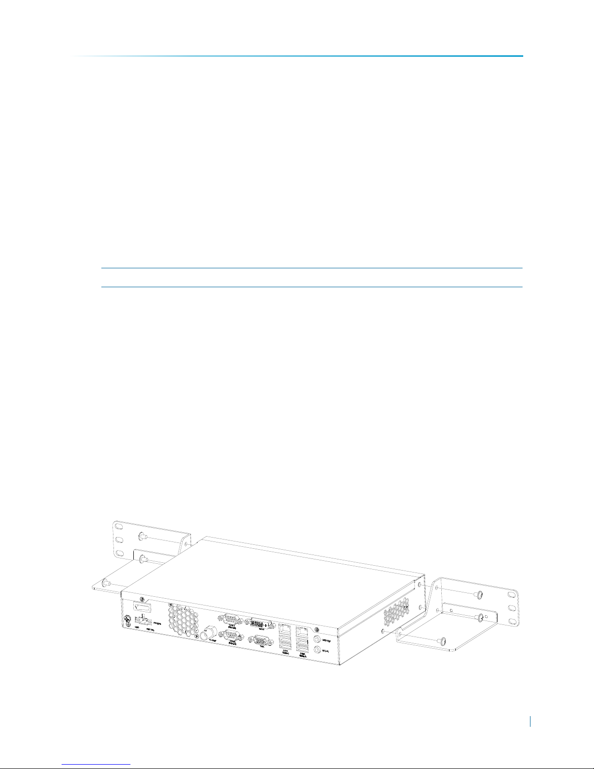
To mount the HDR 1800 on a wall:
1. Align the wall-mount brackets with the holes on the bottom of the HDR 1800.
10
www.verint.com/video_solutions
Chapter 2
Installing the HDR 1800
2. Screw the wall-mount brackets to the HDR 1800 using 12 in-lb (1.35 N-m) force with 4
screws (provided).
3. Place the HDR 1800 on the wall and ensure that there is enough space on the sides of the
unit for ventilation.
NOTE: Ensure the wall is strong enough to support the weight of the HDR 1800: 5.7lb (2.6Kg).
4. Secure the HDR 1800 to the wall using four wall screws (not provided) on each side of the
HDR 1800.
Connecting the HDR 1800
This section provides the procedures for connecting the network and power cables, video
monitors, and CCTV keyboards to the HDR 1800. It includes the following topics:
“Connecting the Network and Power Cables” on page 11
“Connecting Monitors” on page 12
“Connecting a CCTV Keyboard” on page 13
Connecting the Network and Power Cables
This section explains how to connect the network and power cables to the HDR 1800.
To connect the cables for network:
Plug an ethernet cable into the LAN1 network (RJ-45) connector on the back of the HDR
1800.
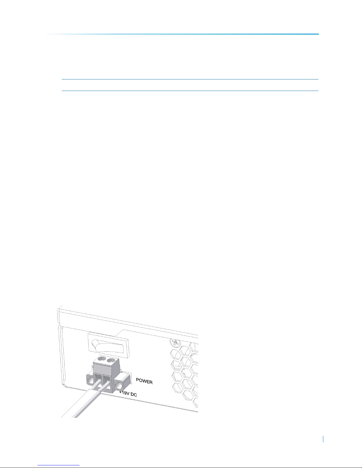
To connect the cable for power:
1. Connect the 19V DC +/-5%, Terminal Block power connector to the power input receptacle
on the back of the HDR 1800.
Verint Video Intelligence Solutions
11

Connecting the HDR 1800
2. Secure the power connector to the receptacle by tightening the screws on each side of the
connector.
3. Plug the 19V DC +/-5% power cable into an outlet or surge-protection device.
Connecting Monitors
You can connect either one monitor (Single monitor configuration) or two monitors (Dual monitor
configuration) to the HDR 1800. In a Dual monitor configuration, the first monitor in the
configuration must be connected to the DVI-D connector on the HDR 1800; the second monitor
can be connected to either the VGA or BNC-Composite (TV Out).
To connect a monitor to the HDR 1800:
Plug the monitor cable into the corresponding video input (DVI-D, VGA, BNC-Composite(TV
Out)) on the back of the HDR 1800.
In a Dual monitor configuration, the first monitor in the configuration must be connected to the
DVI-D connector on the HDR 1800.
NOTE: You can also connect a monitor that uses the HDMI interface to the DVI-D port on the
HDR 1800. You will need an HDMI male to DVI male adapter (not provided).
12
www.verint.com/video_solutions

Chapter 2
54321
9876
54321
9876
Installing the HDR 1800
Connecting a CCTV Keyboard
The HDR 1800 supports all RS-232 and RS-422 CCTV keyboards supported in Nextiva VMS. The
HDR 1800 provides two serial ports for connecting CCTV keyboards:
COM1: RS-232 (DB9)
COM2: RS-422 (DB9)
To connect a CCTV keyboard:
Use the following wiring scheme to connect the CCTV keyboard’s serial cable to the
corresponding serial (DB9) port on the back of the HDR 1800.
RS-232 DB9 Pin
Number
2 RxD 1 Tx-
3 TxD 2 Tx+
5 Signal ground 3 Rx+
7RTS4Rx-
8 CTS 5 Signal ground
Once the connection is done, you must set the baud rate, parity, and other parameters for the
serial port in Nextiva VMS Control Center; for more information, see “Configuring Serial Ports” on
page 34.
Signal on CCTV
Keyboard Cable
RS-422 DB9 Pin
Number
Signal on CCTV
Keyboard Cable
Verint Video Intelligence Solutions
13

Powering On the HDR 1800
Powering On the HDR 1800
Once the power and network cables and monitors are connected to the HDR 1800, you can power
it on.
To power on the HDR 1800:
1. Make sure the power adaptor for the HDR 1800 is connected to a power outlet (or surgeprotection device).
2. Make sure the monitors connected to the HDR 1800 are powered on.
NOTE: If you are using the BNC-Composite (TV out) connection, ensure that the monitor is
connected to the HDR 1800 and turned on before pressing the power button on the
back of the HDR 1800.
3. Press the power button on the back of the HDR 1800. The power led on the front of the HDR
1800 lights up.
When the HDR 1800 first powers on, a splash screen with the HDR 1800’s current IP address
(DHCP or APIPA), unit name, firmware version, and other information appears on all monitors.
By default, the HDR 1800 is DHCP (Dynamic Host Configuration Protocol) enabled. If you have a
DHCP server, the HDR 1800 automatically obtains an IP address upon initial startup from the
DHCP server. If a DHCP server is not available on the network, the HDR 1800 assigns itself a
temporary IP address based on the APIPA (Automatic Private IP Addressing) addressing
format.The APIPA scheme, available on the Windows operating systems, allows a device to
assign itself a temporary IP address until it receives a complete network configuration, either
manually or from a DHCP server. A device in APIPA mode does not reside on the same subnet
as the other devices on the IP network. Therefore, it may not be able to view or be visible by the
other devices. All HDR 1800s use the following temporary APIPA configuration:
IP address: 169.254.X.Y (where X and Y are based on the last two octets of the MAC
address of the HDR 1800)
Subnet mask: 255.255.0.0
Gateway: 169.254. *. *
Regardless of whether the HDR 1800 is using DHCP or APIPA, before you can add the HDR 1800
to the Nextiva VMS system, you must specify its static IP address. For more information on setting
the IP address for the HDR 1800, see Chapter 3, “Configuring the HDR 1800”.
14
www.verint.com/video_solutions

Chapter
Configuring the HDR 1800
This chapter focuses on the configuring the HDR 1800 in Nextiva Video Management
System (VMS).
The following topics are discussed:
Getting Started. . . . . . . . . . . . . . . . . . . . . . . . . . . . . . . . . . . . . . . . . . . . . . . . . . . . . . . . .16
Discovering the HDR 1800 . . . . . . . . . . . . . . . . . . . . . . . . . . . . . . . . . . . . . . . . . . . . . . .17
Configuring Network Settings . . . . . . . . . . . . . . . . . . . . . . . . . . . . . . . . . . . . . . . . . . . . .20
Configuring Monitor Output Settings . . . . . . . . . . . . . . . . . . . . . . . . . . . . . . . . . . . . . . . .22
Registering the HDR 1800 with Nextiva VMS . . . . . . . . . . . . . . . . . . . . . . . . . . . . . . . . .25
Adding the HDR 1800 to Physical and Logical Groups . . . . . . . . . . . . . . . . . . . . . . . . . .27
Viewing and Configuring Physical Settings . . . . . . . . . . . . . . . . . . . . . . . . . . . . . . . . . . .29
Configuring the HDR 1800 in Virtual Matrix. . . . . . . . . . . . . . . . . . . . . . . . . . . . . . . . . . .37
Resetting the HDR 1800 to Partially Discovered State . . . . . . . . . . . . . . . . . . . . . . . . . .43
Restoring Factory Default Settings . . . . . . . . . . . . . . . . . . . . . . . . . . . . . . . . . . . . . . . . .46

Getting Started
Getting Started
Once you install the HDR 1800 in a Nextiva system, it needs to be configured for use with Nextiva
Video Management Software (VMS).
Nextiva VMS, version 6.1 includes the HDR 1800 Service Generator in Nextiva Control Center.
You use the HDR 1800 Service Generator to:
Discover HDR 1800s installed on the network (see “Discovering the HDR 1800” on page 17);
Configure network settings for the HDR 1800, including setting its IP address, subnet mask,
and gateway IP address (“Configuring Network Settings” on page 20);
Configure monitor output settings for the HDR 1800, including setting the tile layout on
monitors connected to the HDR 1800 (“Configuring Monitor Output Settings” on page 22);
Register the HDR 1800 with Nextiva VMS so that it can be added to Physical and Logical
Groups in the Nextiva system (“Registering the HDR 1800 with Nextiva VMS” on page 25).
Once you configure and register the HDR 1800 with Nextiva VMS, you use Nextiva Control Center
to:
Add the HDR 1800 to the Physical and Logical Views (see “Adding the HDR 1800 to
Physical and Logical Groups” on page 27);
Configure Physical settings for the HDR 1800 (see “Viewing and Configuring Physical
Settings” on page 29);
Configure the HDR 1800 in Nextiva Virtual Matrix, including assigning Monitor IDs, startup
video sources, and CCTV keyboards (see “Configuring the HDR 1800 in Virtual Matrix” on
page 37).
NOTE: Ensure that the Nextiva HDR 1800 is running the correct firmware for your Nextiva VMS
configuration before you run the system setup wizard.
16
www.verint.com/video_solutions

Chapter 3
Configuring the HDR 1800
Discovering the HDR 1800
Nextiva VMS, version 6.1 includes the HDR 1800 Service Generator. The HDR 1800 Service
Generator interfaces with HDR 1800s installed on the Nextiva network.
Before you can use an HDR 1800 with Nextiva VMS, you must add it and configure it for use with
Nextiva VMS.
In general, all HDR 1800s installed on the network are automatically discovered. If the HDR 1800
is on a different subnet, you can manually discover the device (see “To discover manually an HDR
1800:” on page 19).
To discover the HDR 1800:
1. Launch Nextiva Control Center.
2. Select Global Settings > Adaptors.
3. Click HDR 1800 Service Generator on the left. The HDR 1800 Service Generator Browser
pane is displayed on the right:
The HDR 1800 Service Generator automatically discovers HDR 1800s connected to the
Nextiva network.
The HDR 1800 Service Generator Browser pane displays general information for the HDR
1800, including:
Name: This column displays the system or device name for the HDR 1800.
Status: This column indicates the current configuration state for each HDR 1800:
Verint Video Intelligence Solutions
17

Discovering the HDR 1800
Partially Discovered: The HDR 1800 is discovered and network and monitor output
settings can now be configured for it. This is the initial configuration state when an
HDR 1800 is first added to the Nextiva system.
Fully Discovered: The HDR 1800 transitions to the Fully Discovered state when
network and monitor output settings are configured for it and when the HDR 1800 is
registered in the Nextiva system. The HDR 1800 can now be added to Physical and
Logical views using the System Setup Wizard.
Configured: The HDR 1800 automatically transitions to the Configured state after
it has been added to Physical and Logical Groups in Nextiva VMS. This state indicates
that the HDR 1800 is available in Nextiva Physical and Logical views and you can
now configure its physical settings.
Foreign Site: The HDR 1800 is installed and registered in another Nextiva site. You
can still configure its network and monitor output settings and register the HDR 1800
with the local Nextiva system; however, you need to transition the HDR 1800 from
the other site to the local Nextiva site, by clicking the Register/Unregister button at
the top of the HDR 1800 Service Generator Browser pane. This sets the HDR 1800
to Fully Discovered state in the local Nextiva site and offline on the other Nextiva site.
IP address: This column displays the IP address of the HDR 1800.
Serial number: This column displays the unit serial number.
Firmware version: This column displays the version number of the firmware
currently installed on the HDR 1800.
System: This column displays the name of the Nextiva site where the HDR 1800 is
currently installed.
NOTE: You can only configure network and monitor output settings for an HDR 1800 in
Partially Discovered state. If you want to change network or monitor output settings for
an HDR 1800 in Fully Discovered or Configured states, you must first reset it to
Partially Discovered state; see “Resetting the HDR 1800 to Partially Discovered State”
on page 43.
18
www.verint.com/video_solutions

Chapter 3
Configuring the HDR 1800
To discover manually an HDR 1800:
1. Under Global Settings > Adaptors, click HDR 1800 Service Generator. The HDR 1800
Service Generator Browser pane is displayed on the right:
2. Click the Add button. The Unit Discovery window appears.
3. Enter the IP address of the HDR 1800 that you want to discover in the IP Address box. For
information on obtaining the IP address, see “Powering On the HDR 1800” on page 14.
4. Click Discover.
5. Repeat step 3 and step 4 if required. Then click Done on the Unit Discovery window.
Verint Video Intelligence Solutions
19

Configuring Network Settings
Configuring Network Settings
Before adding an HDR 1800 to Nextiva VMS, you must configure its network settings. This
involves setting a static IP address and subnet mask for the HDR 1800.
By default, the HDR 1800 is DHCP (Dynamic Host Configuration Protocol) enabled. If you have a
DHCP server, the HDR 1800 automatically obtains an IP address upon initial startup from the
DHCP server; this IP address is then displayed on all monitors connected to the HDR 1800 (upon
initial startup), as well is in Nextiva Control Center.
If a DHCP server is not available on the network, the HDR 1800 assigns itself a temporary IP
address based on the APIPA (Automatic Private IP Addressing) addressing format.The APIPA
scheme allows a device to assign itself a temporary IP address until it receives a complete network
configuration, either manually or from a DHCP server. A device in APIPA mode does not reside
on the same subnet as the other devices on the IP network. Therefore, it may not be able to view
or be visible by the other devices. All HDR 1800s use the following temporary APIPA configuration:
IP address: 169.254.X.Y (where X and Y are based on the last two octets of the MAC
address of the HDR 1800)
Subnet mask: 255.255.0.0
Gateway: 169.254. *. *
Regardless of whether the HDR 1800 is using DHCP or APIPA, before you can register the HDR
1800 with Nextiva VMS and add it to Physical and Logical Groups in the Nextiva system, you must
specify its static IP address.
This section provides the procedure for configuring network settings for the HDR 1800.
NOTE: You can only configure network settings for an HDR 1800 in Partially Discovered
configuration state. To modify monitor output settings for an HDR 1800 that is in the
Fully Discovered or Configured states, you must first reset the HDR 1800 to Partially
Discovered state; see “Resetting the HDR 1800 to Partially Discovered State” on page
43.
To configure network settings for the HDR 1800:
1. In the HDR 1800 Service Generator Browser pane, select a Partially Discovered HDR
1800 that you want to configure.
NOTE: If the HDR 1800 that you want to configure does not appear in the HDR 1800 Service
Generator Browser pane, click the Add button to manually discover the HDR 1800 (see
“To discover manually an HDR 1800:” on page 19), or click the Refresh button to
update the list of discovered HDR 1800s. You can also filter the list of discovered HDR
20
www.verint.com/video_solutions

Chapter 3
Configuring the HDR 1800
1800s to display only Partially Discovered HDR 1800s by clicking the Filter button and
selecting Partially Discovered from the pick list.
2. Select the Network tab.
Verint Video Intelligence Solutions
21

Configuring Monitor Output Settings
3. Type a static IP address for the HDR 1800 in the IP Address box.
4. In the Subnet Mask box, type the subnet mask for the subnet the HDR 1800 is located on.
5. Type the IP address of the server that acts as the access point to another network in the
Gateway IP Address box. The gateway IP address is optional.
6. Click Apply to save the configuration settings.
Once you configure network settings for the HDR 1800, you configure its monitor output settings
(see “Configuring Monitor Output Settings” on page 22), and then register the HDR 1800 with
Nextiva VMS (see “Registering the HDR 1800 with Nextiva VMS” on page 25).
Configuring Monitor Output Settings
Before adding an HDR 1800 to Nextiva VMS, you must configure its monitor output settings. This
involves setting the number of tiles or video outputs to display on each of the monitors connected
to the HDR 1800, as well as setting the connector type (DVI, VGA, or Composite) for the monitors.
NOTE: If you are using the BNC-Composite (TV out) connection, ensure that the monitor is
connected to the HDR 1800 and turned on before restarting the HDR 1800.
The default monitor output settings for the HDR 1800 are as follows:
Dual Monitor (extended desktop) configuration enabled
Monitor 1 Connector Type: DVI
Monitor 1 Tile layout: 2x2
Monitor 2 Connector Type: VGA
Monitor 2 Tile layout: 2x2
You can change the default settings by specifying a different Tile Layout: 1x1, 2x2 (default), 3x2,
3x3, 4x3, 4x4; or by selecting a different Connector Type: DVI, VGA, or Composite.
You can also set monitor output to Single monitor configuration if only one monitor is connected
to the HDR 1800.
Nextiva VMS considers each tile a separate video output on the HDR 1800 and automatically
assigns each tile a Monitor Name when the HDR 1800 is added to Physical and Logical Views.
This section provides the procedure for configuring monitor output settings for the HDR 1800.
NOTE: You can only configure monitor output settings for an HDR 1800 in Partially
Discovered configuration state. To modify monitor output settings for an HDR 1800 that
is in the Fully Discovered or Configured states, you must first reset the HDR 1800 to
Partially Discovered state; see “Resetting the HDR 1800 to Partially Discovered State”
on page 43.
22
www.verint.com/video_solutions

Chapter 3
Configuring the HDR 1800
To configure monitor output settings for the HDR 1800:
1. In the HDR 1800 Service Generator Browser pane, select a Partially Discovered HDR
1800 that you want to configure.
The configuration parameters for the HDR 1800 appear directly below the HDR 1800 Service
Generator Browser pane.
2. Select the Layout tab.
3. Set the following parameters to configure monitor output settings for the HDR 1800:
For a Single monitor configuration:
1) Deselect the Monitor 2 option (selected by default).
2) Select the Tile Layout for Monitor 1.
3) Select the Connector Type for Monitor 1: DVI (default), VGA, or Composite.
Verint Video Intelligence Solutions
23

Configuring Monitor Output Settings
For a Dual monitor configuration:
1) Select the Monitor 2 option. The configuration settings for Monitor 2 are enabled.
In a Dual monitor configuration, the Connector Type for the first monitor in the
configuration automatically switches to DVI and the system prevents you from
changing this setting. You must make sure that Monitor 1 is connected to the DVI port
on the HDR 1800.
The Monitor Type setting for Monitor 2 is always set to Dual (extended desktop);
this setting cannot be changed.
2) Select the Tile Layout for each monitor.
3) Select the Connector Type for Monitor 2: VGA (default) or Composite.
4. Click Apply to save the configuration settings.
Once you configure network and monitor output settings for the HDR 1800 you register it with
Nextiva VMS.
24
www.verint.com/video_solutions

Chapter 3
Configuring the HDR 1800
Registering the HDR 1800 with Nextiva
VMS
When an HDR 1800 is registered with Nextiva VMS, you can use the System Setup Wizard to add
the HDR 1800 to Physical and Logical Groups, configure physical settings (audio output, aspect
ratio, serial ports, etc.) for the HDR 1800 in the Physical View, as well as configure the HDR 1800
in Nextiva Virtual Matrix (assign Monitor IDs, startup video sources, and CCTV keyboards). For
more information, see “Viewing and Configuring Physical Settings” on page 29 and “Configuring
the HDR 1800 in Virtual Matrix” on page 37.
To register the HDR 1800 with Nextiva VMS:
CAUTION: Before registering an HDR 1800 with Nextiva VMS you must make sure that the
network and monitor layout settings for the HDR 1800 are configured properly. If the
HDR 1800 does not have a valid network configuration, the system prevents you
from registering the HDR 1800 with Nextiva VMS.
1. In the HDR 1800 Service Generator Browser pane, select a Partially Discovered HDR
1800 that you want to register with Nextiva VMS.
Verint Video Intelligence Solutions
25

Registering the HDR 1800 with Nextiva VMS
2. Click the Register/Unregister button.
Once the HDR 1800 is updated with the new configuration, its configuration state changes to
Fully Discovered:
You can now use the System Setup Wizard to add the Fully Discovered HDR 1800 to
Physical and Logical Groups in Nextiva VMS; see “Adding the HDR 1800 to Physical and
Logical Groups” on page 27.
26
www.verint.com/video_solutions

Chapter 3
Configuring the HDR 1800
Adding the HDR 1800 to Physical and
Logical Groups
Once the HDR 1800 is configured and registered with the Nextiva system, you add it to Physical
and Logical Groups in Nextiva VMS using the System Setup Wizard. This makes the HDR 1800
available in Physical and Logical Views in Nextiva Control Center where you can view and
configure its physical settings (see “Viewing and Configuring Physical Settings” on page 29).
Adding the HDR 1800 to Physical and Logical Groups also makes the video outputs configured
on the HDR 1800 visible in Nextiva Virtual Matrix where you assign Monitor IDs and startup video
sources to video outputs configured on the device (see “Configuring the HDR 1800 in Virtual
Matrix” on page 37).
NOTE: For more information about Physical and Logical Groups in Nextiva VMS, refer to the
Nextiva 6.1 Administrator Guide.
This section provides the procedure for adding the HDR 1800 to Physical and Logical Groups in
Nextiva VMS using the System Setup Wizard.
To add the HDR 1800 to Physical and Logical Groups in Nextiva VMS:
1. Launch the System Setup Wizard in Nextiva Control Center:
a. Select System Components > Devices.
b. Select the System Setup Wizard icon in the toolbar.
2. Click Next on the Welcome page to assign the HDR 1800 to a Physical Group.
3. Select the HDR 1800 device in the left pane, and holding down the left mouse button drag it
to a Physical Group on the right.
Verint Video Intelligence Solutions
27

Adding the HDR 1800 to Physical and Logical Groups
4. Click Next to assign the video outputs configured on the HDR 1800 to Logical Groups.
NOTE: The number of video outputs available to the HDR 1800 depends on the number of tiles
configured. For example, if you have 2 monitors connected to the HDR 1800, with the
1x1 tile layout setting configured on the first monitor, and the 4x4 tile layout setting
configured on the second monitor, there are 17 tiles or video outputs available for the
HDR 1800.
5. Select the video outputs in the Physical Groups View pane and drag them to one or more
Logical Groups in the Logical Groups View on the right.
A video output can belong to as many Logical Groups as required.
6. Click Next. The Recorder Server assignment page is displayed.
7. Click Next to skip this step. The Summary of changes pages is displayed.
This page lists the modifications that will be made when you click the Finish button.
8. Review the modifications before continuing. At this point, you can click Back to make
corrections or Cancel to exit the wizard without applying any of the modifications.
28
www.verint.com/video_solutions

Chapter 3
Configuring the HDR 1800
9. Click Finish to complete the procedure.
Once you add the HDR 1800 to Physical and Logical Groups in the Nextiva system, you
configure physical settings for the HDR 1800 (see “Viewing and Configuring Physical
Settings” on page 29).
Viewing and Configuring Physical Settings
Once the HDR 1800 has been added to Physical and Logical Groups in the Nextiva system, it
becomes available in Physical and Logical Views in Nextiva VMS.
Physical View allows you to view and configure physical settings for the HDR 1800, including
configuring speaker (audio) output and volume, setting CCTV keyboard communication
parameters, and updating the firmware on the HDR 1800.
NOTE: For more information about Physical and Logical Views in Nextiva VMS, refer to the
Nextiva 6.1 Administrator Guide.
This section describes the following:
“Viewing General Properties” on page 30
“Viewing Network Settings” on page 31
“Setting Audio Output” on page 32
“Setting Aspect Ratio” on page 33
“Configuring Serial Ports” on page 34
“Updating the Firmware” on page 36
Verint Video Intelligence Solutions
29

Viewing and Configuring Physical Settings
Viewing General Properties
The General tab displays general parameters for the HDR 1800.
To view general properties for the HDR 1800:
1. In Nextiva Control Center, select System Components > Devices.
2. Select Physical View. Physical devices appear in a hierarchal tree in the Devices pane.
3. Expand the group where the HDR 1800 you want to view general properties for is located
and select it. Upon selection, components of the selected HDR 1800 (video outputs and
serial ports) appear in the Browser pane. General properties for the HDR 1800 are displayed
in the General tab.
The following information is displayed:
Unit Name: This field displays the system or device name for the HDR 1800.
Country: This field is blank.
Product Type: This field displays the model number of the HDR 1800.
Firmware Version: This field displays the firmware version currently installed on the
HDR 1800.
System Uptime: This field displays the time the HDR 1800 has been operating
without a reboot.
30
www.verint.com/video_solutions

Chapter 3
Configuring the HDR 1800
Viewing Network Settings
The Network tab displays the IP address, subnet mask, and gateway configured on the HDR 1800.
These settings are provided for informational purposes only. They cannot be modified in the
Network tab. To modify network settings for the HDR 1800, see “Configuring Network Settings”
on page 20.
To view network settings for the HDR 1800:
1. In Nextiva Control Center, select System Components > Devices.
2. Select Physical View. Physical devices appear in a hierarchal tree in the Devices pane.
3. Expand the physical group where the HDR 1800 you want to view network settings for is
located and select it. Upon selection, components of the selected HDR 1800 (video outputs
and serial ports) appear in the Browser pane.
4. Select the Network tab.
The following settings are displayed:
DHCP: This field is set to Disabled. Dynamic Host Configuration Protocol (DHCP) is
not supported for the HDR 1800 in Nextiva VMS.
IP Address: This field displays the IP address of the HDR 1800.
Subnet Mask: This field displays the subnet mask configured on the HDR 1800.
Gateway: This field displays the gateway configured on the HDR 1800.
Verint Video Intelligence Solutions
31

Viewing and Configuring Physical Settings
Setting Audio Output
You can configure the HDR 1800 to output audio associated with a specific video output (or tile)
to external audio equipment.
NOTE: Connect external audio equipment to the LINE-OUT connector on the HDR 1800. Audio
output can only be set for a single video output (or tile) configured on the HDR 1800.
To set audio output for the HDR 1800:
1. In Nextiva Control Center, select System Components > Devices.
2. Select Physical View. Physical devices appear in a hierarchal tree in the Devices pane.
3. Expand the physical group where the HDR 1800 you want to set audio output for is located
and select it. Upon selection, components of the selected HDR 1800 (video outputs and
serial ports) appear in the Browser pane.
4. Select the Advanced tab.
5. Configure the following parameters in the Audio section:
From the pick list next to Audio Output Association, select none or the video output
(or tile) configured on the HDR 1800 that you want the audio to be set on. The default
selection is the first video output (or tile) configured on the HDR 1800.
In the text box next to Volume, set the audio volume by typing a value between 1 and
100, where None is no volume and 100 is the highest volume setting. The default
setting is 100.
6. Click Apply.
32
www.verint.com/video_solutions

Chapter 3
Configuring the HDR 1800
Setting Aspect Ratio
Setting aspect ratio on the HDR 1800 allows you to set the way video images are displayed on
monitors. You can choose to either:
keep aspect ratio to etains the width-to-height ratio of the video images displayed on
monitors;
or
disable aspect ratio to stretches the video images to use all available space on the monitors.
NOTE: Setting aspect ratio applies to all video outputs (or tiles) configured on the HDR 1800.
You cannot set aspect ratio for individual tiles.
To set aspect ratio on the HDR 1800:
1. In Nextiva Control Center, select System Components > Devices.
2. Select Physical View. Physical devices appear in a hierarchal tree in the Devices pane.
3. Expand the physical group where the HDR 1800 you want to set aspect ratio for is located
and select it. Upon selection, components of the selected HDR 1800 (video outputs and
serial ports) appear in the Browser pane.
4. Select the Advanced tab.
Verint Video Intelligence Solutions
33

Viewing and Configuring Physical Settings
5. In the Misc section, select one of the following options for the Keep Aspect Ratio
parameter:
True: The original width-to-height ratio of the video images displayed on all video
outputs (or tiles) configured on the HDR 1800 will be retained.
False: Video images displayed on all video outputs (or tiles) configured on the HDR
1800 will be stretched to use all available space within each tile.
NOTE: The default setting is False.
6. Click Apply.
Configuring Serial Ports
When you connect a CCTV keyboard to one of the two serial ports (RS-232 or RS-422) on the
HDR 1800 (see “Connecting a CCTV Keyboard” on page 13), you need to configure the serial port
to properly communicate with the keyboard. This involves configuring communication settings,
such as baud rate and parity, on the serial port to match the settings on the CCTV keyboard. (For
more information on required keyboard settings, refer to the manufacturer’s documentation for the
CCTV keyboard.)
NOTE: Only CCTV keyboards that are supported by Nextiva VMS can be connected to the
HDR 1800. Nextiva VMS supports several manufacturers and models of CCTV
keyboards; for more information on CCTV keyboards supported by Nextiva VMS, refer
to the Nextiva 6.1 Third-Party PTZ Camera and CCTV Keyboard Integration Guide.
To configure a serial port on the HDR 1800:
1. In Nextiva Control Center, select System Components > Devices.
2. Select Physical View. Physical devices appear in a hierarchal tree in the Devices pane.
3. Expand the physical group where the HDR 1800 you want to configure is located and select
it. Upon selection, components of the selected HDR 1800 (video outputs and serial ports)
appear in the Browser pane.
34
www.verint.com/video_solutions

Chapter 3
Configuring the HDR 1800
4. In the Browser pane, select the serial port (RS-232 or RS-422) that you want to configure.
The configuration parameters for the serial port are displayed:
5. Specify the required values, following the manufacturer’s documentation for the keyboard:
Baud Rate: The Baud Rate measures the transmission speed and is calculated in
bits per second. Ensure that the same baud rate is configured on both the keyboard
and serial port.
Data Bit: The list contains 5, 6, 7, or 8.
Line Driver: This value is read-only.
Parity: None, Even or Odd.
Stop Bit: 1 or 2.
6. Click Apply to save the configuration settings.
NOTE: Once you configure the serial port on the HDR 1800 that the CCTV keyboard is
attached to, you need to add the keyboard to Nextiva Virtual Matrix; see “Adding a
CCTV Keyboard” on page 40.
Verint Video Intelligence Solutions
35

Viewing and Configuring Physical Settings
Updating the Firmware
You can update the firmware on the HDR 1800 by using the following procedure.
To update the firmware on the HDR 1800:
1. In Nextiva Control Center, select System Components > Devices.
2. Select Physical View. Physical devices appear in a hierarchal tree in the Devices pane.
3. Expand the physical group where the HDR 1800 you want to update firmware on is located
and select it. Upon selection, components of the selected HDR 1800 (video outputs and
serial ports) appear in the Browser pane.
If you are updating multiple HDR 1800s, select all the applicable units in the Browser pane.
4. Select the Firmware tab. The current firmware, configured on the device, appears in the
Current Firmware Version text box.
5. Select the required firmware from the Select New Firmware drop-down list. If the firmware
does not appear in the list, click Browse and navigate to the directory where it is located.
6. Click Update. The progress of the update is displayed in the Update Progress text box.
7. Click Apply.
36
www.verint.com/video_solutions

Chapter 3
Configuring the HDR 1800
Configuring the HDR 1800 in Virtual Matrix
When you add the HDR 1800 to Physical and Logical Groups in the Nextiva system, all video
outputs (or tiles) configured on the Devices pane are added as monitors in Nextiva Virtual Matrix.
You then use Nextiva Virtual Matrix to assign Monitor IDs and startup video sources to each
monitor configured on the HDR 1800, as well as configure on-screen display (OSD) settings for
the monitors. You can also add CCTV keyboards connected to the HDR 1800 in the Nextiva
system and assign the keyboards to the corresponding serial port (RS-232 or RS-422) on the HDR
1800.
This section describes the following:
“Assigning Monitor IDs” on page 37
“Assigning Startup Video Sources to Monitors” on page 39
“Adding a CCTV Keyboard” on page 40
“Customizing On-screen Display” on page 42
Assigning Monitor IDs
A Monitor ID is used to identify individual video outputs (or tiles) on the HDR 1800. A Monitor ID
is required when using CCTV keyboards for all operation done on a monitor. Nextiva VMS does
not automatically assign Monitor IDs to video outputs (or tiles) on the HDR 1800 when the HDR
1800 is first added to the Nextiva system. You must assign IDs using Nextiva Virtual Matrix.
There are two ways to assign IDs to monitors:
Automatically allow Nextiva VMS to assign sequential Monitors IDs (see “To allow Nextiva
VMS to automatically assign sequential Monitor IDs:” on page 38)
Manually assign Monitor IDs (see “To manually assign Monitor IDs:” on page 38)
Verint Video Intelligence Solutions
37

Configuring the HDR 1800 in Virtual Matrix
To allow Nextiva VMS to automatically assign sequential Monitor IDs:
1. In Nextiva Control Center, select System Components > Virtual Matrix.
2. Select Monitors from the tree view in the left pane.
3. In the Monitors pane on the right side, select the entry in the table corresponding to the
monitor that you want to assign a Monitor ID to. You can select multiple entries by dragging
the mouse cursor over the corresponding rows.
38
4. Click the Add button. The Monitor ID text box displays an automatically generated number
for the selected monitor(s).
5. Click Apply to save your changes.
To manually assign Monitor IDs:
1. In Nextiva Control Center, select System Components > Virtual Matrix.
2. Select Monitors from the tree view in the left pane.
3. In the Monitors pane on the right side, type a value in the Monitor ID text box corresponding
to the monitor that you want to assign a Monitor ID to.
NOTE: Monitor IDs must be unique to each monitor. Make sure to enter a value that is not
currently assigned to another monitor in the system and is not greater than 999. ID 0 is
a reserved value and cannot be assigned to a monitor.
4. Click Apply.
www.verint.com/video_solutions

Chapter 3
Configuring the HDR 1800
Assigning Startup Video Sources to Monitors
This section describes the procedure for assigning a startup video source to a monitor on the HDR
1800.
To assign a start up video source to a monitor:
1. In Nextiva Control Center, select System Components > Virtual Matrix.
2. Select Monitors from the tree view in the left pane.
3. In the Monitors pane on the right side, click the Startup Video Source drop-down list
corresponding to the monitor that you want to assign a video source to. The Startup Video
Source drop-down list displays all cameras that are defined as video sources for this Virtual
Matrix.
4. Select the camera you want to use as a video source for the monitor.
5. Click Apply to save the changes.
Verint Video Intelligence Solutions
39

Configuring the HDR 1800 in Virtual Matrix
Adding a CCTV Keyboard
When connected to an HDR 1800 and integrated with Nextiva VMS, CCTV keyboards can be used
to control PTZ cameras, including panning, tilting, and zooming the cameras; calling camera
patterns and presets; starting camera tours, and acknowledging alarms.
You can connect a CCTV keyboard to one of the two serial ports (RS-232 or RS-422) on the HDR
1800 (see “Connecting a CCTV Keyboard” on page 13). You need to then configure
communication settings, such as baud rate and parity, for the serial port that the keyboard is
connected to (see “Configuring Serial Ports” on page 34), and then add the keyboard to Nextiva
Virtual Matrix.
NOTE: Only CCTV keyboards that are supported by Nextiva VMS can be connected to the
HDR 1800. Nextiva VMS supports several manufacturers and models of CCTV
keyboards; for more information on CCTV keyboards supported by Nextiva VMS, refer
to the Nextiva 6.1 Third-Party PTZ Camera and CCTV Keyboard Integration Guide.
This section describes the procedure for adding a CCTV keyboard connected to the HDR 1800,
in Nextiva Virtual Matrix.
When you configure a keyboard in Virtual Matrix, you need the following information:
Keyboard Name: This is a user-defined setting intended to facilitate identification in the
system.
Serial port: This is the serial port that the CCTV keyboard is connected to on the HDR 1800.
Keyboard protocol: This is the protocol used for network communication. It is specific to the
manufacturer and model.
Group Membership: This is the user group or list of groups that the CCTV keyboard is
assigned to. In Nextiva VMS, CCTV keyboards are assigned to user groups, in order to
manage the features, network parameters, and privileges that the keyboard can access. The
group can be specific to CCTV keyboards or can include administrators and operators. For
more information, refer to the Nextiva 6.1 Administrator Guide.
To add a CCTV keyboard in Virtual Matrix:
1. Connect the CCTV keyboard to a serial port (RS-232 or RS-422) on the HDR 1800 (see
“Connecting a CCTV Keyboard” on page 13).
2. Launch Nextiva Control Center.
3. Configure communication settings for the serial port (that the CCTV keyboard is connected
to) in the Nextiva VMS Physical View for the HDR 1800 (see “Configuring Serial Ports” on
page 34).
4. Select System Components > Virtual Matrix.
5. Select Keyboards in the tree view in the left pane.
40
www.verint.com/video_solutions

Chapter 3
Configuring the HDR 1800
6. In the Keyboards pane on the right side, click the Add button in the toolbar to add a
keyboard entry to the table.
7. Enter a name for the keyboard in the Keyboard Name box.
TIP: Enter a meaningful name to facilitate identification. This name is used to identify the
keyboard in the Groups and Privileges workspace in Nextiva VMS. All Virtual Matrix
keyboards need to be assigned to a Nextiva group, in order to control access to the
Nextiva system from the keyboard. For more information on groups and privileges, refer to
the Nextiva 6.1 Administrator Guide.
8. Select the HDR 1800 and then the serial port that the keyboard is connected to from the
Serial Port drop-down list.
9. Select the protocol for the keyboard, as described in the Nextiva 6.1 Third Party PTZ
Camera and CCTV Keyboard Guide.
10. Click Apply.
Verint Video Intelligence Solutions
41

Configuring the HDR 1800 in Virtual Matrix
Customizing On-screen Display
You can customize the on-screen display (OSD) settings for video outputs (or monitors)
configured on the HDR 1800. Configurable parameters for OSD include:
Time Formats
Date Formats
Live Video Positions and Colors
Playback Video Positions and Colors
NOTE: Settings apply to all video outputs (or monitors) defined in Nextiva Virtual Matrix.
To configure OSD:
1. In Nextiva Control Center, select System Components > Virtual Matrix.
2. Select OSD from the tree view in the left pane.
3. In the Monitors On-Screen Display pane to the right, select Enable On-screen Display, to
show the OSD parameters on your monitors (or video outputs). Deselect this option to hide
them.
The default settings for OSD are displayed. Customize OSD settings as described in the
Nextiva 6.1 Administrator Guide.
42
www.verint.com/video_solutions

Chapter 3
Configuring the HDR 1800
Resetting the HDR 1800 to Partially
Discovered State
If you want to modify network or monitor output settings for the HDR 1800, you need to first reset
it to Partially Discovered state. The procedure to reset the HDR 1800 to Partially Discovered
state varies depending on whether the HDR 1800 is in:
Fully Discovered state, where only network and monitor output settings are configured for
the HDR 1800 and it has not yet been added to Physical and Logical Groups in the Nextiva
system (see “To reset a Fully Discovered HDR 1800 to Partially Discovered state:” on page
43).
Configured state, where the HDR 1800 is available in Physical and Logical Views (see “To reset a
Configured HDR 1800 to Partially Discovered state:” on page 44).
Foreign Site, where the HDR 1800 is installed in another Nextiva site (see “To reassign a HDR
1800 to another Nextiva site:” on page 46).
To reset a Fully Discovered HDR 1800 to Partially Discovered state:
NOTE: Resetting a Fully Discovered HDR 1800 to Partially Discovered state does not affect
network and monitor output settings configured on the HDR 1800. It only makes these
settings configurable again.
1. In the HDR 1800 Service Generator Browser pane, select a Fully Discovered HDR 1800
that you want to reset to Partially Discovered state.
2. Click the Register/Unregister button. You are prompted to confirm the action.
3. Click Yes to continue.
Verint Video Intelligence Solutions
43

Resetting the HDR 1800 to Partially Discovered State
The configuration state for the HDR 1800 changes to Partially Discovered.
You can now reconfigure network and monitor output settings for the HDR 1800; see
“Configuring Network Settings” on page 20 and “Configuring Monitor Output Settings” on
page 22
To reset a Configured HDR 1800 to Partially Discovered state:
CAUTION: To r ese t a Configured HDR 1800 to Partially Discovered state, you must first
1. Select System Components > Devices > Physical View.
.
delete the HDR 1800 from the Nextiva system. This removes the HDR 1800 from
Physical and Logical Groups and from Nextiva Virtual Matrix. Configuration settings
on the HDR 1800, however, are not affected; the HDR 1800 maintains all
configuration parameters, such as network and monitor output settings, serial port
settings, etc.
44
www.verint.com/video_solutions

Chapter 3
Configuring the HDR 1800
2. Expand the physical group where the HDR 1800 you want to reset to Partially Discovered
state is located and select it.
3. Click the Delete button. A confirmation message appears.
4. Click Yes to continue.
The HDR 1800 is removed from all Physical and Logical Groups in the system. All video
outputs (or monitors) configured on the HDR 1800, and all keyboards connected to it are also
removed from Nextiva Virtual Matrix.
The HDR 1800 appears in Fully Discovered state in the HDR 1800 Service Generator
Browser pane. You must now reset the HDR 1800 to Partially Discovered state.
5. In the HDR 1800 Service Generator Browser pane, select the HDR 1800.
6. Click the Register/Unregister button.
The configuration state for the HDR 1800 changes to Partially Discovered. You can now
reconfigure network and monitor output settings for the HDR 1800 and add it to the Nextiva
site again; see “Configuring Network Settings” on page 20 and “Configuring Monitor Output
Settings” on page 22.
Verint Video Intelligence Solutions
45

Restoring Factory Default Settings
To reassign a HDR 1800 to another Nextiva site:
CAUTION: The HDR 1800 will appear in Fully Discovered state on the local Nextiva site, and
offline on the other Nextiva site. From the other Nextiva site, you must manually
remove the HDR 1800 from the Physical and Logical Groups and from the Nextiva
Virtual Matrix.
1. In the HDR 1800 Service Generator Browser pane, select an HDR 1800 in Foreign Site
state.
2. Click the Register/Unregister button. You are prompted to confirm the action.
3. Click Yes to continue.
The HDR 1800 is offline on the other Nextiva system and appears in Fully Discovered state
in the HDR 1800 Service Generator Browser pane on the local Nextiva site.
4. Remove the HDR 1800 from the Physical and Logical Groups from the other Nextiva
system.
5. Reconfigure the network and monitor output settings and add it to the lcoal site. See
“Configuring Network Settings” on page 20 and “Configuring Monitor Output Settings” on
page 22.
Restoring Factory Default Settings
If needed, you can restore the HDR 1800 to factory default settings. This resets all configuration
parameters on the HDR 1800 to default values.
You can only restore factory default settings for an HDR 1800 that is in Partially Discovered or
Foreign Site state. To restore factory default settings on an HDR 1800 in Fully Discovered or
Configured state, you must first reset the HDR 1800 to Partially Discovered state; see
“Resetting the HDR 1800 to Partially Discovered State” on page 43.
46
www.verint.com/video_solutions

Chapter 3
Configuring the HDR 1800
To restore factory default settings on the HDR 1800:
1. In the HDR 1800 Service Generator Browser pane, select an HDR 1800 in Partially
Discovered or Foreign Site state.
2. Click the Reset Factory Settings button. You are prompted to confirm the action.
CAUTION: Restoring factory default settings on an HDR 1800 installed on another Nextiva site
(Foreign Site state), removes the HDR 1800 from the other site. The HDR 1800 will
then appear in Partially Discovered state on the local site, and in Foreign Site
state on the site from where it was removed.
3. Click Yes to continue.
All configuration parameters on the HDR 1800 are reset to factory default settings
NOTE: When restoring factory default settings on an HDR 1800, the firmware currently installed
on the unit is not affected.
.
Verint Video Intelligence Solutions
47


Appendix
Specifications and
Configuration
The following topics are discussed:
Technical Specifications . . . . . . . . . . . . . . . . . . . . . . . . . . . . . . . . . . . . . . . . . . . . . . . . .50
Factory Default Configuration . . . . . . . . . . . . . . . . . . . . . . . . . . . . . . . . . . . . . . . . . . . . .52

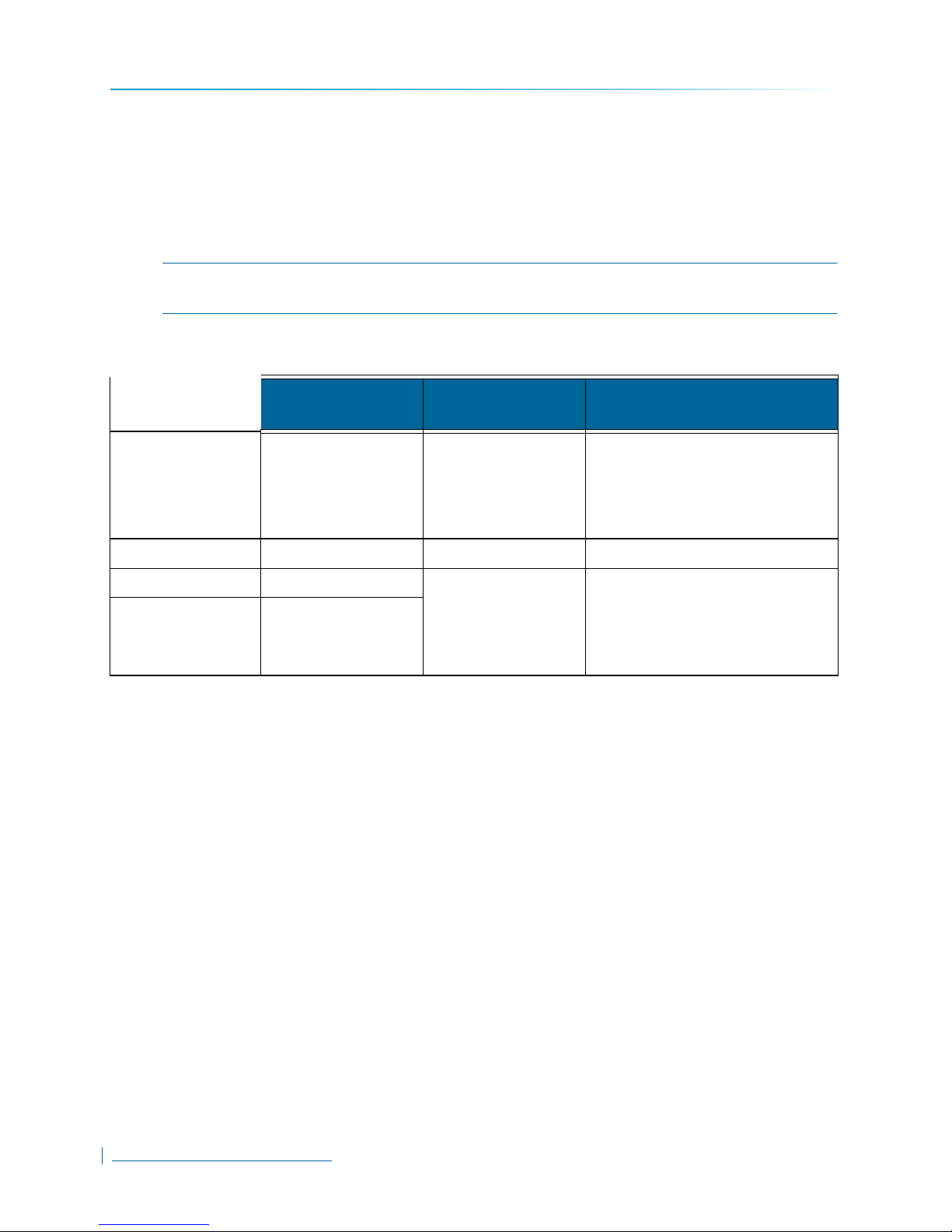
Technical Specifications
Technical Specifications
The following table presents the technical specifications for the Nextiva HDR 1800 :
Video
Outputs/Connectors One Digital DVI-D connector (with HDMI support using an
HDMI male to DVI male connector - not provided)
One VGA (RGB) connector
One BNC connector for composite video (NTSC/PAL)
Monitor Configuration DVI + VGA (RGB)
DVI + BNC (Composite)
DVI only
VGA (RGB) only
BNC (Composite) only
Tiles Tiles display options:
1×1 (1 tile)
2×2 (4 tiles)
3×2 (6 tiles)
3×3 (9 tiles)
4×3 (12 tiles)
4×4 (16 tiles)
Monitor Resolution DVI: Up to 1920×1200
VGA (RGB): Up to 1920×1200
BNC (Composite): 480/576 lines (NTSC/PAL)
Network
Interface 1 RJ-45, Ethernet 10/100/1000 Base-T (for main connectivity)
Interface 2 RJ-45, Ethernet 10/100/1000 Base-T (inactive)
Protocol TCP/IP, UDP/IP, RTSP/RTP, IGMP, FTP, APIPA
Security Nextiva authentication
Ports
Audio One Line Out, 1/8in (3.5mm) Stereo jack for connecting
Serial Ports One RS-232 (DB9) serial port for CCTV keyboard connection
external audio equipment
One Mic in, 1/8in (3.5mm) Stereo jack for 2-way audio
connections (not available)
One RS-422 (DB9) serial port for CCTV keyboard connection
USB Four USB 2.0 ports
50
www.verint.com/video_solutions

Appendix A
Specifications and Configuration
Power
Input Voltage 19V DC +/-5%, Terminal Block, ENERGY STAR Power
supply
Power Consumption 20W, max. 30W
Physical
Enclosure 1U Metal case with flange mount (black)
Dimensions 11W × 7.5D × 1.7H in. (280W × 190D × 44H mm)
Weight 5.7lb (2.6Kg)
Operating Temperature Operating: 32 to 104°F (0 to 40°C)
Humidity 0 to 95% relative, non-condensing at 104°F (40°C)
Mounting Options Rack Mount Kit (included) and Wall/Table Mount Kit
Storage: -22 to 140°F (-30°C to 60°C)
(included)
Management
Configuration and Firmware Upgrade Supported through Nextiva VMS Control Center
Warranty
3-year limited warranty covering parts and labor (for the Americas). Contact your Verint representative
for warranty details for your regions.
Verint Video Intelligence Solutions
51

Factory Default Configuration
Factory Default Configuration
The Nextiva HDR 1800 is programmed at the factory with the following configuration:
Component/Parameter Default Settings
Serial ports (RS-232 and RS-422) Bit rate: 115200 bps
Data bits: 7
Parity: odd
Stop bit: 2
Network DHCP configuration: Enabled
Monitor Output Settings Dual Monitor (extended desktop) configuration enabled
Monitor 1 Connector Type: DVI
Monitor 1 Tile layout: 2×2
Monitor 2 Connector Type: VGA
Monitor 2 Tile layout: 2×2
Audio Output: Tile 1 on Monitor 1
Volume: 100
Aspect Ratio False
Time Zone GMT
Daylight Savings Time adjusted automatically
NOTE: The system time on the HDR 1800 automatically
synchronizes with the Nextiva VMS Master Server.
52
www.verint.com/video_solutions

Glossary
Configuration Assistant
A proprietary graphical program used to
configure and update the firmware of the S1100
edge devices.
This glossary is common to the Nextiva line of
edge device products.
Access Point
A communication hub for connecting wireless
edge devices to a wired LAN.
AES
(Advanced Encryption Standard) An encryption
standard used in the WPA2 authentication
method.
APIPA
(Automatic Private IP Addressing) A feature of
Windows-based operating systems that enables
a device to automatically assign itself an IP
address when there is no Dynamic Host
Configuration Protocol (DHCP) server available
to perform that function. Also known as AutoIP.
Bridge
See Wireless Bridge.
CCTV
(Closed Circuit Television) A television system in
which signals are not publicly distributed;
cameras are connected to television monitors in
a limited area such as a store, an office building,
or on a college campus. CCTV is commonly
used in surveillance systems.
CIF
(Common Intermediate Format) A video format
that easily supports both NTSC and PAL signals.
Many CIF flavors are available, including CIF,
QCIF, 2CIF, and 4CIF. Each flavor corresponds
to a specific number of lines and columns per
video frame.
CLI
(Command Line Interface) A textual user
interface in which the user responds to a prompt
by typing a command.
Codec
(Coder/Decoder) A software library that
compresses or decompresses a video stream
following a specific protocol.
Decoder
See Receiver.
DHCP
(Dynamic Host Configuration Protocol) A
communication protocol that lets network
administrators manage centrally and automate
the assignment of Internet Protocol (IP)
addresses in a network.
DVR
(Digital Video Recorder) A device (usually a
computer) that acts like a VCR in that it has the
ability to record and play back video images. The
DVR takes the feed from a camera and records
it into a digital format on a storage device which
is most commonly the hard drive.
Edge Device
A Nextiva device transmitting or receiving video
signals through an IP network. The devices can
be wireless or wired; some transmitters are IP
cameras.
Encoder
See Transmitter.
Ethernet
A local area network (LAN) architecture using a
bus or star topology and supporting data transfer
rates of 10, 100, and 1000 Mbps. It is one of the
most widely implemented LAN standards. The
802.11 protocols are often referred to as
“wireless Ethernet.”
Firmware
Software stored in read-only memory (ROM) or
programmable ROM (PROM), therefore
becoming a permanent part of a computing
device.
H.264
Also known as MPEG-4 AVC (Advanced Video
Coding), is a video compression standard that
offers significantly greater compression than its
predecessors.
IP
(Internet Protocol) The network layer for the
TCP/IP protocol suite widely used on Ethernet
networks.
Verint Video Intelligence Solutions
53

Glossary
LAN
(Local Area Network) A computer network that
spans a relatively small area. A LAN can connect
workstations, personal computers, and
surveillance equipment (like edge devices). See
also WAN.
MPEG-4
A graphics and video lossy compression
algorithm standard that is derived from MPEG-1,
MPEG-2, and H.263. MPEG-4 extends these
earlier algorithms with synthesis of speech and
video, fractal compression, computer
visualization, and artificial intelligence-based
image processing techniques.
Multicast
Communication between a sender and multiple
receivers on a network; the devices can be
located across multiple subnets, but not through
the Internet. Multicast is a set of protocols using
UDP/IP for transport.
NTSC
(National Television Standards Committee) The
North American standard (525-line interlaced
raster-scanned video) for the generation,
transmission, and reception of television signals.
In addition to North America, the NTSC standard
is used in Central America, a number of South
American countries, and some Asian countries,
including Japan. Compare with PAL.
NTP
(Network Time Protocol) A protocol designed to
synchronize the clocks of devices over a
network.
OSD
(On-screen Display) Status information
displayed on the video monitor connected to a
receiver edge device.
Point-to-Point Connection
The association of a transmitter and a receiver to
view video coming from an analog camera on an
analog monitor.
PSK
(Pre-Shared Key) A mode of the WPA and
WPA2 security protocols, designed for home
and small office networks that cannot afford the
cost and complexity of an authentication server.
It is also known as personal mode.
PTL
(Push-To-Listen) In a two-way system, the
communication mode in which the listener must
push a button while listening.
PTT
(push-To-Talk) In a two-way system, the
communication mode in which the talker must
push a button while talking.
PTZ Camera
(Pan-Tilt-Zoom) An electronic camera that can
be rotated left, right, up, or down as well as
zoomed in to get a magnified view of an object or
area. A PTZ camera monitors a larger area than
a fixed camera.
QoS
(Quality of Service) A set of low-level networking
protocols giving higher priority to more important
data flows while ensuring that the less important
ones do not fail.
Receiver
A device converting a digital video signal into an
analog form. Also called decoder.
Repeater
A range extender for wireless links.
PAL
(Phase Alternation by Line) A television signal
standard (625 lines) used in the United Kingdom,
much of western Europe, several South
American countries, some Middle East and
Asian countries, several African countries,
Australia, New Zealand, and other Pacific island
countries. Compare with NTSC.
PEAP
(Protected Extensible Authentication Protocol) A
method to securely transmit authentication
information, including passwords, over a
wireless network.
54
www.verint.com/video_solutions
RF
(Radio Frequency) Any frequency within the
electromagnetic spectrum associated with radio
wave propagation. When a modulated signal is
supplied to an antenna, an electromagnetic field
is created that is able to propagate through
space. Many wireless technologies are based on
RF field propagation.
RS-232
A standard interface approved by the Electronic
Industries Alliance (EIA) for connecting serial
devices.

Glossary
RS-422
A standard interface approved by the Electronic
Industries Alliance (EIA) for connecting serial
devices, designed as an alternative to the older
RS-232 standard because it supports higher
data rates and greater immunity to electrical
interference.
RS-485
An Electronics Industry Alliance (EIA) standard
for multipoint communications.
SConfigurator
A proprietary graphical program used to
configure and update the firmware of edge
devices.
Serial Port
An interface that can be used for serial
communication, in which only one bit is
transmitted at a time. A serial port is a generalpurpose interface that can be used for almost
any type of device.
SSL
(Secure Sockets Layer) A commonly used
protocol for transmitting private documents via
the Internet. SSL works by using a public key to
encrypt data that is transferred over the SSL
connection. The SSL protocol secures the
following data: I/O, serial port, and VSIP
communication; it does not apply to audio and
video transmission.
TKIP
(Temporal Key Integrity Protocol) A security
protocol used in the WPA authentication
method.
TLS
(Transport Layer Security) A cryptographic
protocol that provide secure communications on
a wireless network.
TTLS
(Tunneled Transport Layer Security) A
cryptographic protocol that creates a secure TLS
tunnel.
VSIP
(Video Services over IP) A proprietary
communication protocol for sending messages
between a computer and a Nextiva edge device,
or between two devices.
WAN
(Wide Area Network) A computer network that
spans a relatively large geographical area.
Typically, a WAN consists of two or more local
area networks (LANs).
WEP
(Wired Equivalent Privacy) A security protocol
for wireless local area networks (WLANs)
defined in the 802.11b standard. It is designed to
afford wireless networks the same level of
protection as a comparable wired network.
Wireless Bridge
A link between two networks, wired or wireless.
Wireless Cell
A group of wireless devices that communicate
together on the same radio frequency channel
and share the same wireless passkey.
Wireless Transmission
A technology in which electronic devices send
information to receivers using radio waves rather
than wiring.
WPA
(Wi-Fi Protected Access version 1) An
authentication method to secure wireless
systems. It is the successor of WEP. WPA
implements the majority of the IEEE 802.11i
standard.
Transceiver
(Transmitter/Receiver) A device that both
transmits and receives analog or digital signals.
Transmitter
A device sending video signals captured with a
connected camera to a receiver. The transmitter
converts the analog signal into a digital form
before transmitting it. Also called encoder.
WPA2
(Wi-Fi Protected Access version 2) An
authentication method that implements the full
802.11i standard, but will not work with some
older network cards. It is also known as 802.11i.
Verint Video Intelligence Solutions
55


Index
C
casing of the unit 9
configuration
default
52
D
default configuration 52
E
enclosure, unit 9
equipment list
F
8
factory default configuration 52
L
loading default configuration 52
O
options, when ordering a device 8
P
panel of unit 9
R
reset to factory default 52
RoHS
B
RS-422/485
12, 13
Verint Video Intelligence Solutions
57


For more information, please visit us at www.verint.com/video_solutions
Americas: info@verint.com
EMEA: marketing.emea@verint.com
APAC: marketing.apac@verint.com
All other trademarks and product names are the property of their respective owners.
The information in this document may be superseded by subsequent documents.
Revision 1

60
www.verint.com/video_solutions
 Loading...