

Page 1

VESTA LOG FIRE
VLF45NG, VLF45NG, VLF45P, VLF45P
Manual & Remote Operated Models
THIS IS NOT
A ‘DO-IT-YOURSELF’ PRODUCT
THIS APPLIANCE MUST BE INSTALLED
BY A CORGI REGISTERED PERSON
INSTALLATION, USERS AND
SERVICING INSTRUCTIONS
THESE PRODUCTS ARE APPROVED TO THE EUROPEAN GAS DIRECTIVE
Article I. PLEASE LEAVE THESE INSTRUCTIONS
WITH THE USER
0120
Page 2

2
Contents
Page No.
List of components
3
Appliance Data
3
GENERAL INSTALLATION REQUIREMENTS
3
Fitting the Appliance
4
Fitting the appliance into the optional Radiant Firebox
5
Additional notes for handset remote control model
6
Assembling the fire & the placing of the logs
8
COMMISSIONING
10
Check for spillage
10
Briefing the User
10
USERS GUIDE
11
Useful tips & recommendations
11
Operation of your appliance
11
Manual Appliances
12
Remote Appliances
13
Cleaning your fire
14
SERVICING & MAINTENANCE
15
Spares Parts list
16
Guarantee
17
Installation & Service Record
18
Important Notes – Please read before undertaking the installation
1. This is not a “Do it yourself” product and it must be installed by a
competent person.
2. The chimney must be swept before the appliance is fitted.
3. The Installation Instructions must be adhered to without exception.
Page 3
3
Before fitting this appliance, ensure that the following list of components are
enclosed
(a) Vesta Burner unit
(b) 1 Set Ceramic Base Pieces (1 Base, 1 LH Side, 1 RH Side, 1 Front, 1 Burner.)
(c) 1 Log Set (4 Pieces)
(d) Installation, User & Servicing Instructions
(e) For Handset Remote Models only 1 Handset Control unit c/w 9V alkaline battery
1 Signal receiver (with mount)
1 Battery Charger c/w lead & jack plug
1 Rechargeable Battery pack & wiring harness
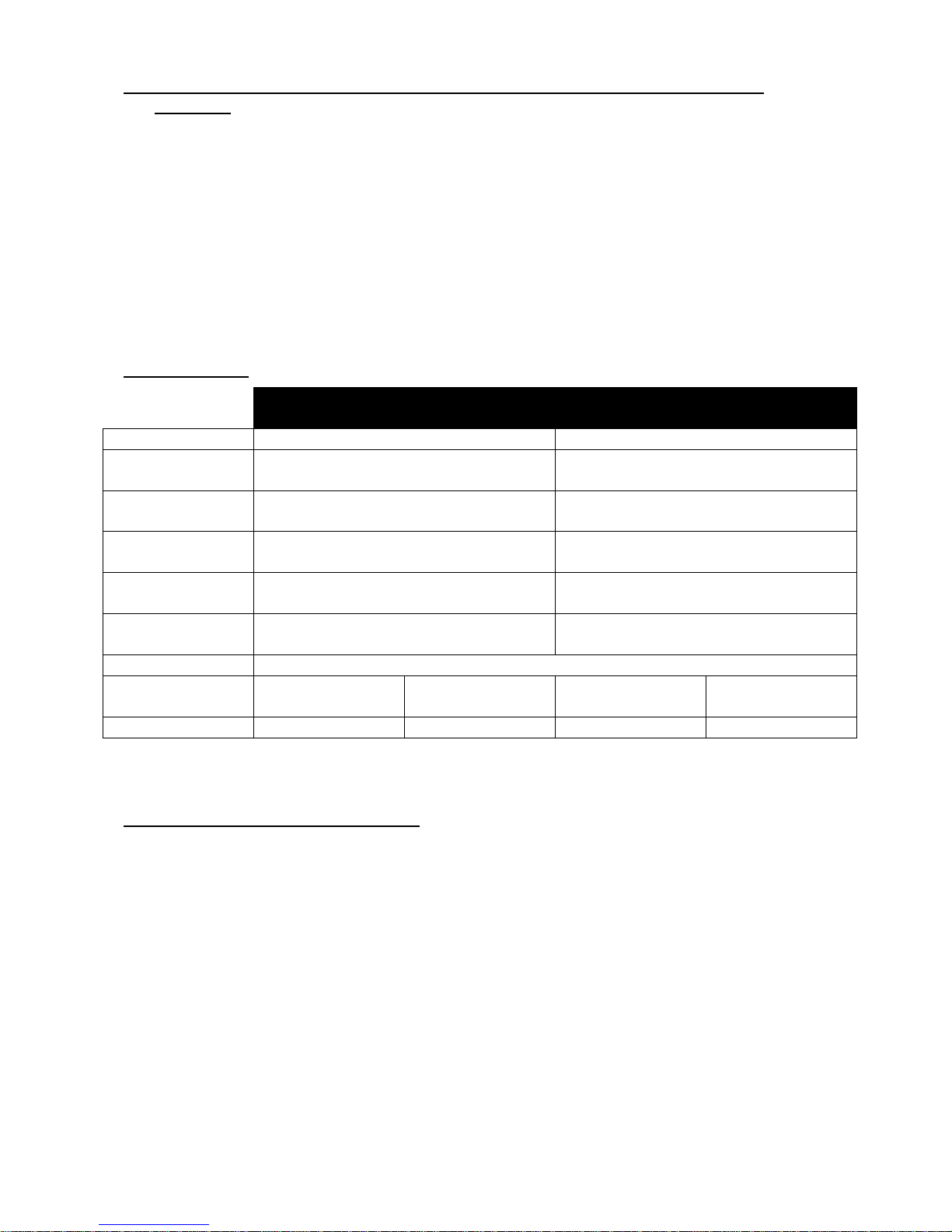
APPLIANCE DATA
VLF45NG
(Manual)
VLF45NG
(Remote)
VLF45P
(Manual)
VLF45P
(Remote)
Gas Type
Natural Gas
Propane
Heat Input
(Gross) (kW)
11.0
10.3
Supply Pressure
(mbar)
20
37
Injector Size
(mm)
2.75
1.6
Injector Setting
(High) (mbar)
14.5
28.0
Injector Setting
(Low) (mbar)
5.5
7.0
Gas Connection
8mm Compression
Fuse Rating
(Amps)
N/A
3
N/A
3
Weight (Kg)
3.5
4.5
3.5
4.5
Dimensions of burner: 450mm wide, 250mm deep, 190mm high.
GENERAL INSTALLATION REQUIREMENTS
1 The law demands that all gas appliances are installed by a qualified installer in
accordance with the current Gas Safety (Installation and Use) Regulations. The
installation must comply with these installation instructions and all relevant parts of
Local and National Building Regulations or Building Standards (Scotland)
(Consolidation) Regulations and those relevant recommendations of the following
British Standards.
BS 5871: Part 2 BS 8303 BS 5440: Parts 1 and 2 BS 1251 BS 6891
The current IEE wiring regulations, Local Building Regulations and the Building
Standards (Scotland) (Remote Models only).
These Installation Instructions must be adhered to without exception.
Page 4
4
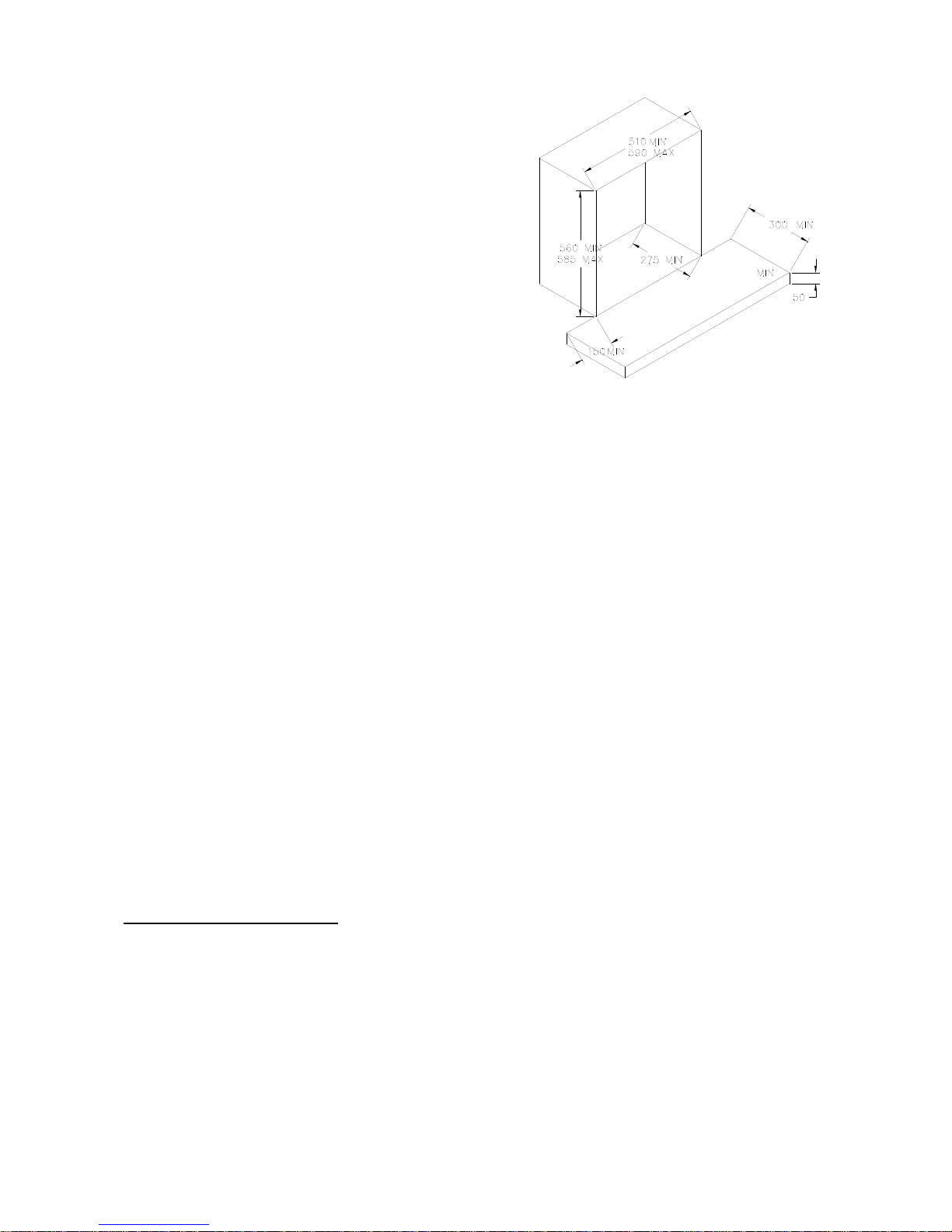
2 FIREPLACE See figure 1
The radiant fireboxes can be fitted to
fireplaces which meet the dimensional
requirements shown in figure 1.
Basket installations require a fireplace
large enough to accommodate the
basket chosen.
Decorative frets should have a
minimum of 50cm2 (8 sq. ins.) of free
air space through the ash cover to
ensure adequate air supply for both
convection air and burner combustion.
3 THE HEARTH
The hearth must be made of a non combustible material at least 12mm in thickness
and must meet the dimensional requirements shown in figure 1. The Heating
Appliances (Fireguards) (Safety) Regulations 1991 are part of the Consumer
Protection Act. It is a criminal offence to fit a Euroglow Inset burner into a fireplace
where the periphery of the hearth is less than 50mm (2”) above the floor level.
Under BS 5871: Part 2 the installation of a fender of 50mm (2”) height will satisfy the
height requirement.
4 THE CHIMNEY FLUE
For radiant firebox installations the chimney should be of the open-flue type and
have a minimum cross sectional dimension of not less than 175mm. For basket
installations the cross section size and the height should be matched to the cross
section of the fireplace opening (See BS 5871 Part 3).
5 The flue must have a minimum effective height of 3 metres.
6 No restrictor plate or flue damper is permitted. Where a variable damper is fitted,
this must be removed or fixed permanently in the fully open position.
7 The chimney must be swept before the appliance is installed and a flue test in
accordance with National Regulations must be carried out.
8 VENTILATION
The room containing the appliance must have a permanent air vent of at least
100cm². The vent must be direct to outside air or to an adjacent room having a
permanent vent of the same area.
FITTING THE APPLIANCE
1 Check that the fireplace is large enough to accept the selected basket. See figure 1.
2 Check that the ignition system functions correctly. Push and turn the control knob
and check that a spark is generated at the pilot burner. If no spark is evident then
check the soundness of the leads.
3 Check the tightness of the nut at the control valve end of the thermocouple.
CAUTION: Do not over tighten.
4 It is recommended that, before proceeding further, a simple smoke test be performed
to check the condition of the chimney. Light a smoke match or a twist of rolled
paper, hold it within the fireplace opening and observe the behaviour of the smoke.
FIGURE 1
Page 5

5
If it is being drawn into the chimney proceed with the installation. If not, preheat the
chimney over the period of a few minutes and recheck. If there is any doubt about
the soundness of the chimney a smoke pellet should be used after preheating the
flue and if smoke still fails to clear, further investigation of the chimney is required
and the appliance MUST NOT be fitted.
5 The gas supply should be routed from the meter or cylinder to a point convenient to
the fireplace.
6 Cut and form a section of 8mm pipe, only rigid and semi-rigid tube is acceptable and
run this into the fireplace opening. If a concealed fitting is required, care must be
taken to sleeve the supply pipe when fitting through masonry.
7 Place the appliance centrally within the fireplace opening. N.B. No part of the
appliance should project beyond the vertical opening of the fireplace opening.
8 Using the nut and olive provided, connect the 8mm supply pipe to the combined
pressure test point and isolator fitting.
Gas Soundness Check
9 With the gas supply connected, all joints should be checked for gas soundness in
accordance with BS 6891.
NOTE: It is permissible to light the fire FOR SHORT PERIODS ONLY when the fire
is not laid with ceramics and logs.
FITTING THE APPLIANCE INTO THE OPTIONAL RADIANT FIREBOX
1 Check that the fireplace or recess is of the correct size to receive the radiant firebox.
See Figure 1.
Note: BS 5871 Part 2: requires a debris collection space of 12 dm3.
2 It is recommended that, before proceeding further, a simple smoke test be performed
to check the condition of the chimney. Light a smoke match or a twist of rolled
paper, hold it within the fireplace opening and observe the behaviour of the smoke.
If it is being drawn into the chimney proceed with the installation. If not, preheat the
chimney over a period of a few minutes and recheck. If smoke still fails to clear,
further investigation of the chimney is required and the appliance MUST NOT be
fitted.
3 In either case, clear the recess of any loose material. Ensure that the base on which
the firebox will stand is level and that the base of the recess and the hearth are
horizontal and non-combustible.
4 Slide the firebox into the opening, ensuring that the flue outlet is unobstructed and
give a clear passage for the products of combustion to the flue. (Do not seal at this
stage.)
5 The firebox should be fitted in such a manner as to be removable, for the purposes
of chimney-sweeping and easy removal of debris.
6 The gas supply should be routed from the meter or cylinder to a point convenient to
the fireplace.
7 Decide whether the gas supply is to be routed through the sides or back of the
firebox, or across the front of the fireplace. Grommeted holes are provided in the rear
and side of the box. Having determined the position of the gas pipe the appropriate
grommet can be pierced with a knife. Provision will have to be made to pass the
pipe through the masonry of the fireplace. The supply pipe should be run to make
removal for servicing easy.
Page 6

6
8 Cut and form a section of 8mm pipe, only rigid or semi-rigid tube is acceptable, and
run this into the fireplace opening. If a concealed fitting is required, care must be
taken to sleeve the supply pipe when passing it through masonry. Exposed pipe
within the fire opening should be wrapped, painted with bituminous paint, or be
factory sheathed.
9 Seal the firebox into the fire opening using the sealing tape provided or a water
based mastic.
10 Fit the burner unit into its mounting brackets within the firebox.
11 Prior to connecting the burner to the gas supply, it is advisable to blow out the pipe
to clear any dirt that may be present and which could cause a blockage in the control
valve or pilot.
12 Using the nut and olive provided, connect the 8mm supply pipe to the combined
pressure test point and isolator fitting.
13 Complete the installation of the appliance as above.
ADDITIONAL NOTES FOR HANDSET REMOTE CONTROL MODEL
1 The installation of the appliance should be carried out following the procedures as
per the section entitled “Fitting the Appliance” on page 4.
2 After installing the burner, positions must be found for the battery pack and the Infra
Red (IF) signal receiver. The fret and ash pan cover will have to be put in position to
find the best place for these items.
3 Battery
Place the battery pack on the hearth along the front of the fire just behind the ash
pan cover. DO NOT PLACE THE BATTERY PACK UNDER THE FIRE.
4 Plug the small jack plug from the charger into its socket at the end of the battery
pack and plug the charger into the mains and switch on to give the batteries a top up
charge.
FIGURE 2
Page 7

7
5 Charging the battery pack
The charger supplied with the battery pack is a true charger and will not overcharge
the batteries. The charger has a built in switch so that it will switch off when the
batteries in the pack are fully charged. The red LED on the front face of the charger
will light when there is current passing to the batteries.
6 The batteries can be
charged either when
they are run down and
the fire will not light
(the control box under
the fire should emit a
series of ‘beeps’ if an
attempt is made to
light the fire when the
batteries do not have
sufficient charge) or
on a regular basis as
convenient to the
user. The batteries
used are of the nickel
– metal - hydride type
that do not suffer
memory problems if they are not discharged completely before being re-charged. A
20 - 30 minute charge should be enough to enable the fire to be lit but a full charge
will take several hours. It may be convenient to leave the charger connected
overnight. DO NOT LEAVE THE CHARGER CONNECTED TO THE BATTERY
PACK WHEN THE FIRE IS IN USE.
FIGURE 3
FIGURE 4
Page 8

8
FIGURE 5
7 IR Signal Receiver
The signal receiver should be placed on the hearth just behind the ash pan cover
such that it is visible to the user operating the remote control handset. If the
receiver is covered in any way the fire will not operate. The receiver is secured
to a bracket with a screw which can be removed when the burner is taken out for
service. The bracket should be fixed to the hearth with the double sided tape
provided after having selected a suitable position for it with the fret and ash pan
cover in position (See Figure 5). The signal receiver must be positioned on the
bracket with the raised part facing the user.
8 Fitting the Battery to the Handset
Before using the
appliance remove
the access cover in
the rear of the
handset and insert
a 9-volt PP3 size
battery. Connect
the battery by
pushing the
connector on to the
terminals. Make
sure the battery is
connected correctly.
Replace the access cover.
ASSEMBLING THE FIRE AND PLACING THE LOGS
WARNING
This product uses fuel effect pieces containing Refractory Ceramic Fibre
(RCF), which are man-made vitreous silicate fibres along with fibrous glass
and mineral wool. Excessive exposure to these materials may cause temporary
irritation to eyes, skin and respiratory tract; consequently, it makes sense to
take care when handling these articles to ensure that the release of dust is
kept to a minimum.
FIGURE 6
Page 9

9
CAUTION All the ceramic components are fragile and should be handled with
care.
1 The burner tray and base ceramics are illustrated in figure 6. Position the burner
ceramic making sure that the holes are aligned with the burner ports. Take the front
ceramic and place it on the burner tray in front of the burner ports. Lay the base
ceramic on the ramp behind the front ceramic. Place the side ceramics either side of
the base ceramic.
2 With reference to figure 7 on the following page, lay the logs as follows;
a) Place the largest log in its moulded seat at the rear of the base ceramic.
b) Place the small branch log in its seats on the left hand side and front ceramics
and rest it on the upstand of the base ceramic.
c) Place the log with a burnt cut-out on its seat on the right hand side ceramic.
d) Place the small v-shaped log in position on the front ceramic and rest it on the
large log and the front logs.
FIGURE 7
Page 10

10
COMMISSIONING
When commissioning your appliance, remove the cap from the isolator fitting and
unscrew the plug all the way out. Replace the cap making sure that the tab engages
with the slot in the top of the plug. Tighten cap securely. Light the appliance in
accordance with the instructions relevant to the appropriate control. (See following
sections for details)
CHECK FOR SPILLAGE
1 Before briefing the customer on how to use the appliance, a spillage test must be
carried out with the appliance and decorative fret in position. The following
procedure must be followed.
2 Close all doors and windows in the room or space containing the appliance.
3 Light a smoke match and pass completely along the front edge (and just inside the
top edge) of the fireplace or firebox. A visual check should ascertain that all the
smoke generated is drawn back into the firebox.
4 If there is evidence of spillage, the flue should be heated for a period of 5 to 10
minutes and the test repeated.
BRIEFING THE USER
1 Demonstrate the full operation of the appliance to the customer, referring them
specifically to the lay of the logs and the removal of soot, as described in these
instructions.
2 Inform the customer that all cleaning procedures should be carried out only when the
appliance is cold.
3 Leave these instructions with the customer.
4 Advise the importance of having the appliance serviced and the chimney checked for
clearance of combustion products on an annual basis.
Page 11

11
USERS GUIDE
USEFUL TIPS AND RECOMMENDATIONS
Once your fire has been fitted, the following recommendations are made to ensure
you enjoy the best results from your purchase;
1 The installation of this appliance must be carried out by a qualified installer and in
accordance with the requirements of the Gas Safety (Installation & Use)
Regulations
2 The chimney must be swept before the appliance is installed and checked annually
to ensure continued clearance of combustion products and that there is no excessive
build-up of soot.
3 As with any fire, certain components will become hot in use, e.g. the decorative front
fret. Care should be exercised when using the control of the appliance when it is
hot. We also recommend that a fireguard, conforming to BS 6539 or BS 6778, be
fitted for the protection of young children, the elderly or infirm.
4 When new, the ceramic logs may produce a slight odour, but this will completely
vanish after a few hours of use.
5 Handle logs gently (See warning on Page 8). They are fragile. A soft brush can be
used to clean them of any excess soot. UNDER NO CIRCUMSTANCES should logs
be washed.
6 Never throw cigarette ends or other foreign matter onto the fire.
7 Never leave the house unattended, with the fire alight, for long periods.
8 Check periodically that the purpose-made ventilation is free from obstruction.
9 To obtain the best results from your log fire we recommend that the fire be serviced.
In order that the terms and conditions of your warranty (see page 17) are met, this
must be undertaken annually and the Service Engineer must complete the Service
Record. (Page 18)
10 These instructions are provided to assist you to operate the fire correctly and should
be kept in a safe place.
11 This appliance is intended for decorative purposes.
12 This appliance is fitted with a flue blockage device that will shut off the appliance in
the event of abnormal flue conditions. This device is NOT a substitute for an
independently mounted carbon monoxide detector.
13 It is a characteristic of the re-chargeable Nickel - Metal Hydride batteries that power
the control system is that they deliver almost full power until they are nearly
completely discharged. This means that the first indication that the battery pack
needs charging is that the fire will emit a series of ‘beeps’ when an attempt is made
to light the fire from cold and the pilot burner will not remain alight. A 20 minute
charge will probably be enough to light the fire but this should be followed by full
charge as soon as the fire is not required.
OPERATION OF YOUR APPLIANCE
1 It should be noted that your fire is fitted with a Flame Supervision Device, which cuts
off the gas supply to your fire if, for any reason the pilot light is extinguished. It also
monitors constantly the oxygen in the room. The pilot flame heats the thermocouple
probe and allows gas to flow to the burners. If due to pilot failure, the thermocouple
cools, no gas will flow to the main burner. If the fire is turned off or the flames go
out, wait for AT LEAST 3 MINUTES before attempting to relight the fire.
Page 12

12
2 When the fire is first lit, the flames tend to be rather blue in colour. Once the core of
the fire becomes hot, the flames will become yellow and more lifelike. During this
initial warm-up period it is recommended that the control remains in the ‘MAX’ or
‘HIGH’ position. This permits the fire to reach its optimum condition more quickly.
3 For convenience you will find with the appliance a card giving concise lighting
instructions, please keep this in a safe place. For full details see the relevant
appliance instruction on pages 12 – 14
LIGHTING THE APPLIANCE
Manual Appliances
1 Remove the ash pan cover (if fitted) below the decorative fret in the front of the fire.
2 Push in and turn the control knob (see figure 8) anti-clockwise to the ‘PILOT’
position & hold in for several seconds to purge any air from the system. If the fire
has not been used for some time or is new this may take half a minute or more as
the air can only purge through the very small orifice in the pilot burner injector.
During this purge time you can try lighting the pilot burner (see next paragraph)
every ten seconds or so but after each attempt remember to return the control knob
to the ‘pilot’ position and keep it depressed.
3 Lighting the pilot burner is done by turning the control knob, still depressed, from the
‘OFF’ position to the ‘PILOT’ position when the spark generator will be heard to
‘click’ as a spark is produced which should light the pilot burner. If the pilot does not
light try again after a few seconds. The
pilot may not light at the first attempt.
Waiting a few seconds gives the spark
generator time to recover.
4 Once the pilot burner is alight continue to
depress the control knob for a further 10 –
15 seconds and then release. The pilot
should stay alight. If it goes out repeat the
process, only this time keeping the control
knob depressed for a slightly longer
period.
5 Depress the control knob slightly and turn
anti-clockwise to the ‘MAX’ position. The
main burner should now light.
6 Turn the control knob anti-clockwise to the
‘MIN’ position. The flames will get lower
but the main burner should remain alight.
Turning the fire off
7 To turn off the burners, depress the control knob slightly and turn clockwise to the
‘PILOT’ position. The main burner should go out but the flame should remain alight.
8 Depress the control knob slightly and turn to the ‘OFF’ position. The pilot flame
should go out.
IMPORTANT
After turning ‘OFF’, or if the pilot or the appliance go out for any reason, wait 3
minutes before attempting to relight.
Page 13

13
Remote Appliances
9 Using the handset
When using the handset make sure that it is
pointed at the infra red signal receiver
located under the front of the fire (the small
black pad). Unlike a TV control the fire does
not react to a quick press on the button on
the handset control. The buttons must be
pressed and held until the control box under
the fire acknowledges the signal by emitting
a 'beep' sound (this can take two or three
seconds) and then released. When the
handset is emitting a signal the yellow LED
at the top of the control will flash.
10 Lighting the Fire See Figure 9
To light the fire press the OFF and the
STAND BY buttons together on the handset
until the fire control box answers with a
'beep' and then released. The fire will go
through its start - up procedure by lighting
first the pilot burner and then the main
burner on high fire. This procedure takes
about 30 seconds. If the fire does not light or
there is no reaction when the two buttons are pressed, press the OFF button to reset the control and try again.
11 Adjusting the Flame Height
To turn the fire from high to low, press and release the low fire button as soon as the
'beep' is heard and the flame height will reduce. If the fire is set at high and a flame
height between high and low fire is desired, press and continue to hold the low fire
button after the 'beep' has sounded. The flame height will gradually decrease.
Release the button when the desired height of flame is achieved. To turn the fire
from low fire to high fire press and (after the 'beep' is sounded) release the high fire
button. To gradually increase the flame press and hold the button as described
above for the low fire button.
12 Turning the Fire OFF
To turn the fire off but leave the pilot burner alight press the STAND-BY button until
the 'beep' is heard. Use this facility to conserve battery life if the fire is going to be
used again later in the day. To turn the fire completely off press the OFF button. The
STAND-BY button and the OFF button can be pressed when the flame is at any
height. To light the main burner from the STAND-BY position press either the HIGH
FIRE or LOW FIRE buttons.
13 Manual OFF Facility
If, whilst the fire is alight, the handset control is lost or its battery becomes
discharged the fire can be turned off by pressing and holding the manual off button
situated on the fascia underneath the front of the burner. This button disconnects the
battery from the control box and the fire will go out after the button has been held in
for about a minute. Care should be taken as the fret / ash pan cover as well the
burner facia will be hot.
Figure 11
FIGURE 9
Page 14

14
14 Replacing the batteries
As stated above, the batteries are of the nickel – metal - hydride type which have a
long life and are able to be re-charged many times. Eventually, due to age and use,
a point will come when they need recharging at inconveniently short intervals and
they will have to be replaced. The batteries are AA size and should be of 1.2 volts
and at least 1300mAH capacity. This type of battery is readily available through retail
and trade outlets.
15 To change the batteries
a) When the fire is cold lift away the ash pan cover.
b) Locate the battery pack under its heat shield.
c) Invert the battery pack and bend the securing tab outwards. Slide the battery holder
out of the heat shield.
d) Remove the batteries from their holder and replace with new batteries. Observe the
correct polarity of the batteries in their holder.
e) Slide the battery holder back into the heat shield and re-bend the securing tab.
f) Plug the charger into the battery pack and to the mains. The red LED on the charger
should come on. If it does not, check the polarity of the batteries and all connections.
Charge the batteries overnight, or as indicated by the instructions that were included
with the new batteries.
CLEANING YOUR FIRE
1 Ensure that the fire is cold before undertaking any cleaning. Remember that heat is
retained for some time after the fire is switched off. In normal use your fire requires
only minimal cleaning. Soot may form on the logs but this is generally harmless and
can easily be removed by lifting the relevant logs from the fire and cleaning them
with a soft brush. If it is necessary to remove all logs for cleaning then any soot or
debris should be removed from the ceramic element and from the burner.
2 As with all metal products, the trim on the fire may tarnish over a period of time. The
metal finish is covered with a lacquer and should only be washed with mild
detergent. On no account use any abrasives or metal polish on the trim.
3 If large pieces of debris are found in the fire, sufficient to alter the appearance or
operation of the appliance, the chimney / flue should be inspected and the appliance
serviced before further use.
4 In any event, the chimney should be checked annually to ensure continued
clearance of the combustion products and that there is no excessive build-up of soot.
Page 15

15
SERVICE AND MAINTENANCE
WARNING
This product uses fuel effect pieces containing Refractory Ceramic Fibre (RCF),
which is man-made vitreous silicate fibres along with fibrous glass and mineral wool.
Excessive exposure to these materials may cause temporary irritation to eyes, skin
and respiratory tract; consequently, it makes sense to take care when handling these
articles to ensure that the release of dust is kept to a minimum.
The appliance should be serviced annually by a CORGI registered engineer.
This is the basic procedure.
1 The ceramic pieces should be taken off the fire and shaken to remove any debris
and soot particles but should only be cleaned if absolutely necessary. This should be
done by gently brushing with a soft brush in a direction away from the person and
any persons nearby. This operation should be performed outside facing downwind. A
vacuum cleaner must not be used for this purpose. Badly damaged logs should be
replaced. Replacement logs and ceramic pieces are available via our stockists.
2 The gas supply should be turned off at the combination pressure test point and
isolator fitting. Disconnect the burner from the gas supply, remove any burner fixings
and lift away the burner.
3 Remove all debris and soot from the burner and thoroughly clean the burner ports.
4 The pilot burner fitted is an oxygen depletion pilot burner and is the primary safety
device on the appliance. It must therefore be replaced annually. After changing the
pilot burner operate the spark generator and observe that the spark is satisfactory.
5 Lay the burner on a flat surface and remove, clean and replace the main injector.
6 Any soot or debris should be removed from the fireplace and flue. The flue should be
inspected for soundness and a smoke test performed as described in the fitting
section to check the condition of the flue.
7 Replace and fix the burner in position. Re-connect to the gas supply. Check all joints
for gas soundness.
8 Light the burner and check that it functions correctly. Re-light the pilot burner. Check
that the pilot flame is satisfactory. Check correct functioning of the thermocouple and
magnet valve (housed within the control valve). This is done by turning the control
knob to the pilot position and then blowing out the pilot burner. Time the period
between the blowing out of the pilot burner and hearing the 'click' of the magnet
valve closing. If this period exceeds 60 seconds the magnet valve will also have to
be replaced.
9 Replace the burner ceramics and rebuild the fuel lay as described in the installation
section. Light the fire and, after allowing it a few minutes to warm up, make final
adjustments to the logs to obtain a satisfactory visual affect.
AFTER REFITTING THE APPLIANCE CHECK FOR GAS SOUNDNESS AT ALL
GAS JOINTS AND TEST FOR SPILLAGE.
10 The service record sheet is enclosed with these instructions and should be
completed to maintain the validity of the five year warranty
Page 16

16
SPARE PARTS LIST
In the event of a part requiring replacement the parts list is as follows
DESCRIPTION
VERINE PART
NUMBER
OXYGEN DEPLETION PILOT ASSEMBLY (NATURAL GAS ONLY).
P47
OXYGEN DEPLETION PILOT ASSEMBLY (L.P.G. PROPANE ONLY).
P48
GAS CONTROL BM VALVE (NATURAL GAS MANUAL) INC. PIEZO & HT LEAD
P12
SPECIAL ORDER
GAS CONTROL BM VALVE (L.P.G. MANUAL) INC. PIEZO & HT LEAD
P12
SPECIAL ORDER
GAS CONTROL BM VALVE (NATURAL GAS & L.P.G S/C) INC. PIEZO & HT LEAD
P12
SPECIAL ORDER
SIT TANDEM 830 SOLENOID VALVE (NATURAL GAS & L.P.G. S/C ONLY)
P97(22NG)
EXTERNAL SWITCH LEAD.
SC13
BRASS WALL SWITCHPLATE.
SC2
WHITE WALL SWITCHPLATE.
SC3
LOG/CERAMIC SET – BURNER TRAY.
VO28
FIREBOX CERAMIC LINING.
H63
HIGH TEMPERATURE FIREBOX/STOVE PAINT SATIN BLACK – CAN.
P55
BLACK MAGIC COAL/CERAMIC RESTORER – CAN.
P56
SENSOR DOUBLE SOLENOID VALVE
SC10
SENSOR HAND HELD UNIT
SC10H
SENSOR RECEIVER UNIT
SC10R
Page 17

17
GUARANTEE.
1. The appliance is guaranteed for one year from the date of purchase.
2. This guarantee is given subject to the following provisions:-
a) The installation is carried out by a CORGI registered person.
b) That the fireplace conforms to the requirements given in the Installation
Instructions for this appliance.
c) That our instructions covering cleaning and handling are adhered to.
This guarantee does not cover mishandling.
d) That the guarantee card supplied with every purchase is returned to us
for registration within four weeks of the date of purchase with the details
correctly filled in.
e) That any part or parts on which a claim is made are returned to us
postage paid for inspection.
f) That our liability is limited to free replacement of the parts affected.
g) The guarantee does not cover (1) Normal wear and tear. (2) Possible
discolouration of polished parts. (3) Replacement of batteries.
h) The remote battery pack, if fitted, is guaranteed against faults but battery
life is not guaranteed as this is dependant on usage, the battery is also
not guaranteed if it is damaged due to heat if the instructions on
placement are not followed.
Page 18

18
Installation & Service Record
Please ensure that installer completes the installation record below
INSTALLATION RECORD
Appliance Supplied by: …………………………....
Installation Date: ……………Serial No.: ….……...
Installed By: …………..…...CORGI No.: …..……
Signed by Installer: ……………………………..…
RECORD OF 1st SERVICE
Serviced by: ………… CORGI No.:…………....
Service Date: …………… Signed: ….…….…...
Comments: ……………………………………………
……………………………………………………………
……………………………………………………………..
RECORD OF 2nd SERVICE
Serviced by: ………… CORGI No.:…………....
Service Date: …………… Signed: ….…….…...
Comments: ……………………………………………
………………………………………………………………
…………………………………………………………..
RECORD OF 3rd SERVICE
Serviced by: ………… CORGI No.:…………....
Service Date: …………… Signed: ….…….…...
Comments: ……………………………………………
……………………………………………………………
……………………………………………………………..
RECORD OF 4th SERVICE
Serviced by: ………… CORGI No.:…………....
Service Date: …………… Signed: ….…….…...
Comments: ……………………………………………
………………………………………………………………
…………………………………………………………..
RECORD OF 5th SERVICE
Serviced by: ………… CORGI No.:…………....
Service Date: …………… Signed: ….…….…...
Comments: ……………………………………………
……………………………………………………………
……………………………………………………………..
RECORD OF 6th SERVICE
Serviced by: ………… CORGI No.:…………....
Service Date: …………… Signed: ….…….…...
Comments: ……………………………………………
………………………………………………………………
…………………………………………………………..
RECORD OF 7th SERVICE
Serviced by: ………… CORGI No.:…………....
Service Date: …………… Signed: ….…….…...
Comments: ……………………………………………
……………………………………………………………
……………………………………………………………..
RECORD OF 8th SERVICE
Serviced by: ………… CORGI No.:…………....
Service Date: …………… Signed: ….…….…...
Comments: ……………………………………………
………………………………………………………………
…………………………………………………………..
RECORD OF 9th SERVICE
Serviced by: ………… CORGI No.:…………....
Service Date: …………… Signed: ….…….…...
Comments: ……………………………………………
……………………………………………………………
……………………………………………………………..
RECORD OF 10th SERVICE
Serviced by: ………… CORGI No.:…………....
Service Date: …………… Signed: ….…….…...
Comments: ……………………………………………
………………………………………………………………
…………………………………………………………..
Page 19

19
Page 20

20
Verine Limited
52 Broton Drive Trading Estate
Halstead, Essex CO9 1HB
Tel: (01787) 472551 Fax: (01787) 476589
Email: sales@verine.co.uk
Website: www.verine.co.uk
LOG/1006/II&UI THIS BOOKLET CONTAINS 20 PAGES
 Loading...