

Page 1

Fontana HE
Model No. NPHL**RN
HIGH EFFICIENCY LOG EFFECT ROOM HEATER
Installation, Maintenance & User Instructions
Hand these instructions to the user
Model No. NPHL**RN is for use on Natural Gas (G20) at a supply pressure of
20 mbar in G.B. / I.E.
** Denotes trim & colour variant
Page 2

CONTENTS
PAGE
Section 1 Information and Requirements
1
.0 Appliance information 3
1
.1 Conditions of installation 4
1.2 Flue & Chimney Suitability 4
1
.3 Shelf position 5
1
.4 Hearths 5
1.5 Installation to plastered wall surfaces 5
Section 2 Installation of Fire
2.1 Unpacking the combustion chamber 6
2.2 Preparing the combustion chamber opening (In studded wall) 7
2.3 Preparing the combustion chamber opening (In chimney breast) 8-9
2.4 Securing the fire to the opening 10
2.5 Installation of the gas supply 11
2.6 Fitting the efficiency / flue restrictor baffle 12
2.7 Fitting the batteries to the fire 12
2.8 Removal & re-fitting of the glass frame 13
Section 3 Assembling Fuel Bed and Commissioning
3.1 Fitting the fuel bed logset 14-18
3.2 Making the gas connection & checking for gas tightness 18
3.3 Removal & re-fitting the trim 19
3.4 Lighting the appliance - SIT RC system equipped models 20-25
3.5 Lighting the appliance - Mertik Maxitrol system equipped models 26-30
3.6 Checking for clearance of combustion products 31
Section 4 Maintenance
4.1 Removal of the burner assembly 32
4.2 Removal of the control valve 32-33
4.3 Removal of the ultrasonic reciever 33
4.4 Removal of the pilot assembly 33
4.5 Removal / Replacement of the control board 33
4.6 Removal / Replacement of the handset battery 34
Section 5 User Instructions
5.1 Installation Information 35
5.2 About the Proclaim HE room heater 36
5.3 Spillage monitoring system 37
5.4 Lighting the appliance - SIT RC system equipped models 38-43
5.5 Lighting the appliance - Mertik Maxitrol system equipped models 44-48
5.6 Cleaning Instructions 49
5.7 Removal & re-fitting the fuel-bed logset 50-54
5.8 Removal & re-fitting the glass frame 55
5.9 Removal & re-fitting the trim assembly 56
5.10 User replaceable parts 57
5.11 Changing the batteries in the RC handset 57
5.12 Changing the batteries in the fire 57
Model number NPHL**RN manufactured by:-
BFM Europe Ltd. Trentham Lakes, Stoke-on-Trent, Staffordshire, ST4 4TJ
2
Page 3
SECTION 1
INFORMATION AND REQUIREMENTS
1.0 APPLIANCE INFORMATION
Main injector : (1 off) Stereomatic Injector Cat 82 – size 380 (NG)
Pilot Type : Copreci ODS 21100 / 162 (SIT RC System)
Copreci ODS 21100 / 141 (Mertik Maxitrol
RC system)
Max. Gross Heat Input : 5.4 kW
Min. Gross Heat Input : 3.0 kW
Gas Rate : 0.512 m3/hr (High)
0.290 m3/hr (Low)
Cold Pressure : G20 20.0+/-1.0 mbar (8.0 +/- 0.4 in w.g.)
Ignition : Integral to gas valve
Electrode Spark Gap : 4.0mm
Packed Weight Combustion Chamber : 48.0 kg
Appliance Efficiency Declaration
The efficiency of this appliance has been measured as specified in BS EN 7977-1
: 2002 and the result is 78%. The gross calorific value of the fuel has been used
for this efficiency calculation. The test data from which it has been calculated has
been certified by GL Industrial Services UK Ltd. The efficiency value may be used
in the UK Government’s Standard Assessment Procedure (SAP) for energy rating
of dwellings.
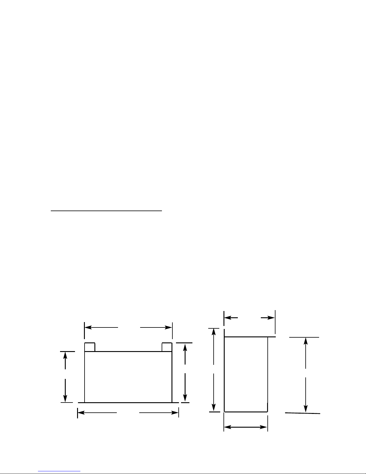
Fig. 1 Fig. 2
Top View of Combustion Side View of Combustion
Chamber Chamber
3
797 mm
728 mm
351 mm
515mm
560mm
351mm
385mm
385mm
Page 4

INSTALLATION REQUIREMENTS
1.1 CONDITIONS OF INSTALLATION
It is the law that all gas appliances are installed only by a GAS SAFE Registered
Installer, in accordance with these installation instructions and the Gas Safety
(Installation and Use) Regulations 1998 as amended. Failure to install appliances
correctly could lead to prosecution. It is in your own interest and that of safety to
comply with the law. The installation must also be in accordance with all relevant
parts of the Local and National Building Regulations where appropriate, the
Building Regulations (Scotland Consolidation) issued by the Scottish Development
Department, and all applicable requirements of the following British Standard Code
of Practice.
1. BS 5871 Part 2 Installation of Inset Live Fuel Effect Gas Fires
2. BS 6891 Installation of Gas Pipework
3. BS 5440 Parts 1 & 2 Installation of Flues and Ventilation
4. BS 1251 Open fire place components
5. BS 715 / BS EN 1856-2 Metal flue pipes for gas appliances
6. BS EN 1858 Clay Flue Blocks and Terminals
7. IS 813 : Domestic Gas Installation (Republic of Ireland)
No purpose made additional ventilation is normally required for this
appliance, when installed in G.B. When Installing in I.E. please consult
document I.S. 813 : Domestic Gas Installation, which is issued by the
National Standards Authority of Ireland. If installing in Northern Ireland,
please consult local building regulations. Any purpose made ventilation
must be checked periodically to ensure that it is free from obstruction.
1.2 FLUE AND CHIMNEY SUITABILITY
This appliance is designed for use with conventional brick built or lined chimneys
and fabricated flues and metal flue boxes conforming to BS 715 / BS EN 1856-2.
All flues must conform to the following minimum dimensions.
Minimum diameter of circular flues 125 mm
Minimum effective height of all Class 1 (175mm) flues 3 metres
Minimum effective height of all Class 2 (125mm) flues 4 metres
ENSURE THAT IF INSTALLING THIS PRODUCT INTO A BRICK BUILT
CHIMNEY, THE CHIMNEY HAS BEEN FULLY SWEPT PRIOR TO PROCEEDING
WITH THE INSTALLATION.
Safe clearance of products must always be checked by carrying out a smoke
match test as described in section 3.7
4
Page 5
1.3 SHELF POSITION
The fire may be fitted below a combustible shelf providing there is a minimum
distance of 300mm above the top of the fire and the shelf does not project more
than 150mm. If the shelf overhangs more than 150mm the distance between the
fire and the shelf must be increased by 15mm for every 25mm of additional
overhang over 150mm.
1.4 HEARTHS
This appliance does not require the fitting of a hearth that projects in front of it
when installed into a recess in either an existing chimney breast or a studded wall.
The appliance must however stand on a non-combustible base that is a minimum
thickness of 12mm
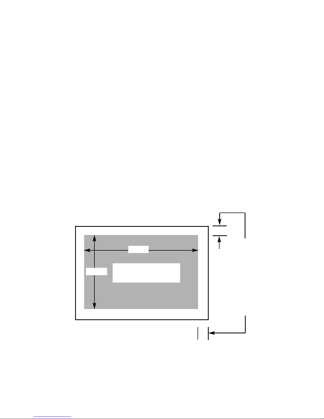
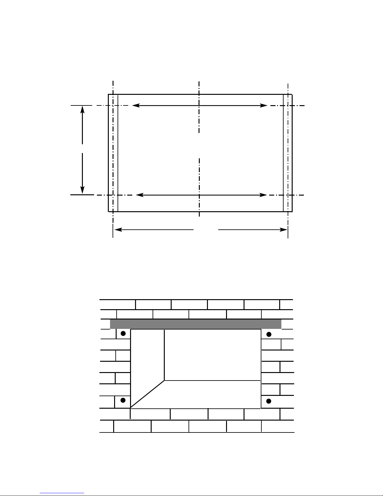
1.5 INSTALLATION TO PLASTERED WALL SURFACES
If installing to a plastered wall, all material must be removed from the 50mm area
surrounding the combustion chamber opening, and replaced with non-combustible
material, such as marble or granite, to prevent plaster cracking. See Fig. 3 below
Fig. 3
5
Combustion Chamber
Opening in Studded Wall or
Existing Chimney Breast
750mm
520mm
Minimum 50mm of
material to be removed
all round perimeter of
combustion chamber
and replaced with
marble, granite or other
non-combustible
material to create a
sealing area. Secure
combustion chamber via
four off mounting holes
in mounting frame
Page 6

SECTION 2
INSTALLATION OF FIRE
2.1 UNPACKING THE COMBUSTION CHAMBER
Carefully lift the combustion chamber out of the carton. Remove the loose item
packaging carefully from the pack. Check the contents as listed :-
DO NOT UNDER ANY CIRCUMSTANCES USE THIS APPLIANCE IF THE
GLASS PANEL IS BROKEN OR NOT SECURELY FIXED TO THE FIREBOX.
Packing Check List
1 off Combustion Chamber & Glass Frame Assembly
1 off Trim assembly
1 off Boxed ceramic fuel-bed set (packed inside combustion chamber)
1 off Installation / User Instruction manual
1 off Rubber grommet (to seal inlet aperture used on firebox)
1 off Handset & 1 off 9V Battery or 3 off AAA Batteries (dependent upon RC
system)
1 off Loose Items pack – containing :- 1 off Efficiency Baffle
8 off No. 12 x 40mm Screws
8 off Rawlplugs
4 or 6 off off AA Batteries
(dependent upon RC system)
1 off handset wall bracket
(dependent upon RC system)
IMPORTANT NOTE BEFORE PROCEEDING WITH THE INSTALLATION
This product requires a minimum effective flue height of 4.0 metres of minimum
circular cross-sectional area 125mm. If installing the product into a 225mm x
225mm brick chimney, THE CHIMNEY SOUNDNESS MUST BE CHECKED BY
TESTING prior to a decision being made on whether the chimney requires lining.
If the flue height is greater than 10 metres on an external wall or 12 metres on an
internal wall then a flue liner must be fitted even if the chimney integrity is ok
.
Please check the chimney height and integrity prior to proceeding with the
installation, to establish if a chimney liner is required. Any flue pipe should
conform to BS 715 / BS EN 1856-2 (Metal flue pipes for gas appliances).
When you have decided upon if the product requires the fitting of a flue
liner, proceed with the creation of the correct sized builders opening or
studwork installation of the product as per sections 2.2 or 2.3
6
Page 7
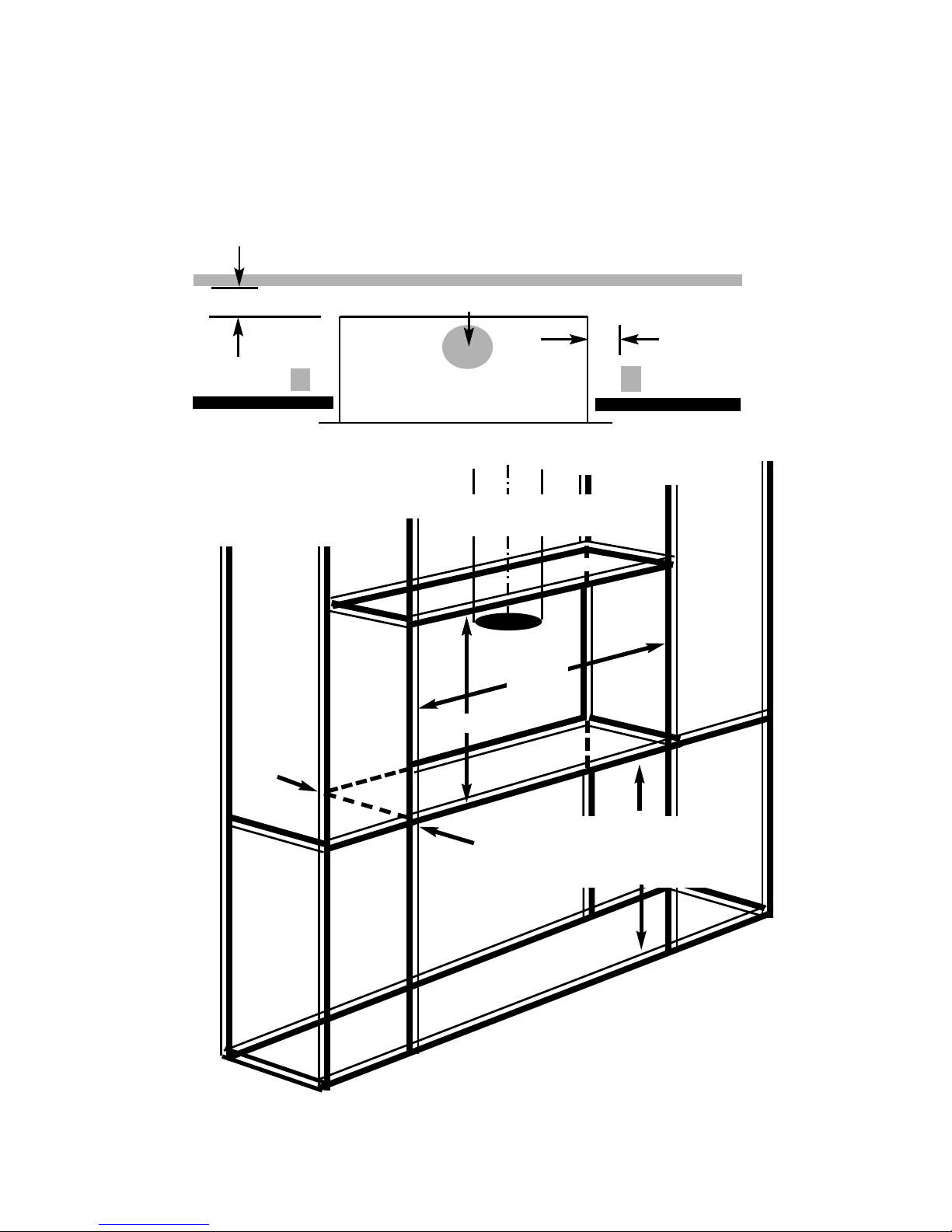
2.2 PREPARATION OF THE COMBUSTION CHAMBER OPENING
(INTO STUDDED WALL) USING A 125MM FLUE LINER.
All combustible parts of the studwork must be set at the distances as shown below
in Fig. 4 & 5. For installation into such applications a flue box with 125mm flue
pipe adaptor is available to purchase as a cost option extra, please order part
number 1125-130260, from your local Verine stockist.
7
Minimum 50mm at sides
Minimum 50mm at rear
Combustion Chamber
Dimension “A”
Opening
Width = 750mm
Dim “A”
Dim “B”
Dimension “B”
Opening
Height = 520mm
Dim “C”
Dimension “C”
Opening
Depth = 385mm
Fig. 4
Fig. 5
A minimum clearance of
100mm is required above
the top of the draught
diverter to combustible
surfaces
M
inimum 125mm flue liner required
125mm diameter minimum
flue liner required
MINIMUM HEIGHT FROM
FLOOR LEVEL TO
BOTTOM OF OPENING IS
150MM
Page 8
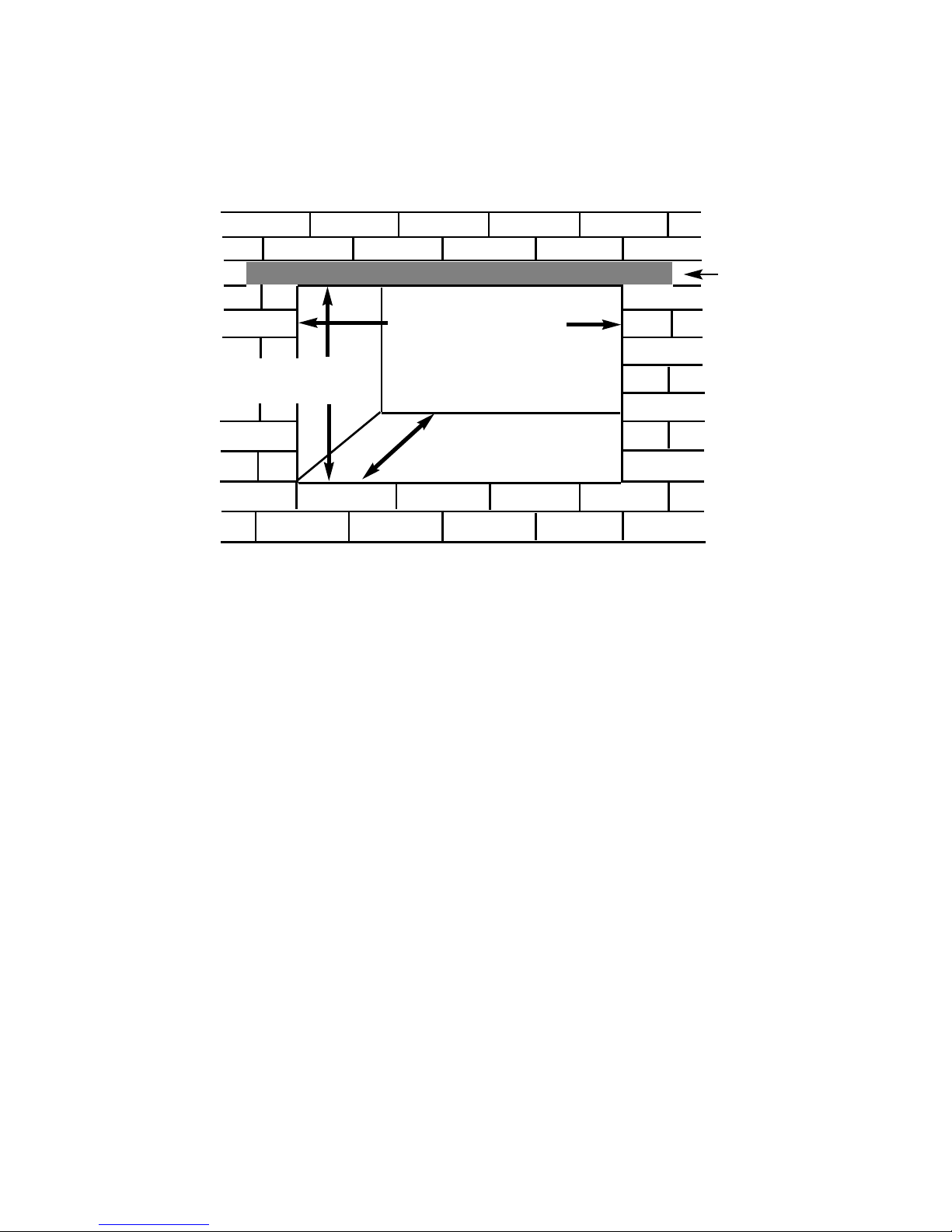
2.3 PREPARATION OF THE COMBUSTION CHAMBER OPENING
(INTO EXISTING CHIMNEY BREAST)
An opening should be constructed to the following dimensions in the existing
chimney breast. See fig. 6 below
Fig. 6
NOTE : Please ensure that access holes are cut into either the sides or area
above the lintel to allow access to the flue pipe connection if using a flue liner.
Such access holes are also advantageous in installations where a flue liner is not
required as they provide access for servicing purposes.
If installing without a flue liner, please ensure that sufficient depth is available in
the opening to collect a minimum volumetric area of 12 litres (0.012m3) of flue
debris. This is achieved by a minimum depth of 385mm, the design of the outer
combustion chamber ensures this depth can be met.
Refer to Fig. 1 on page three for dimensions of the flue outlet.
CHECK ANY LOAD BEARING STRUCTURAL ITEMS ARE NOT
AFFECTED BY THE INSTALLATION OF THE PRODUCT. SEE FIG 6
OVERPAGE.
8
Opening Width = 750mm
Opening Height = 520mm
Minimum Depth 385mm
with or without liner
L
intle must
p
roject 150mm
either side of the
opening if
cutting into an
existing chimney
breast
Page 9
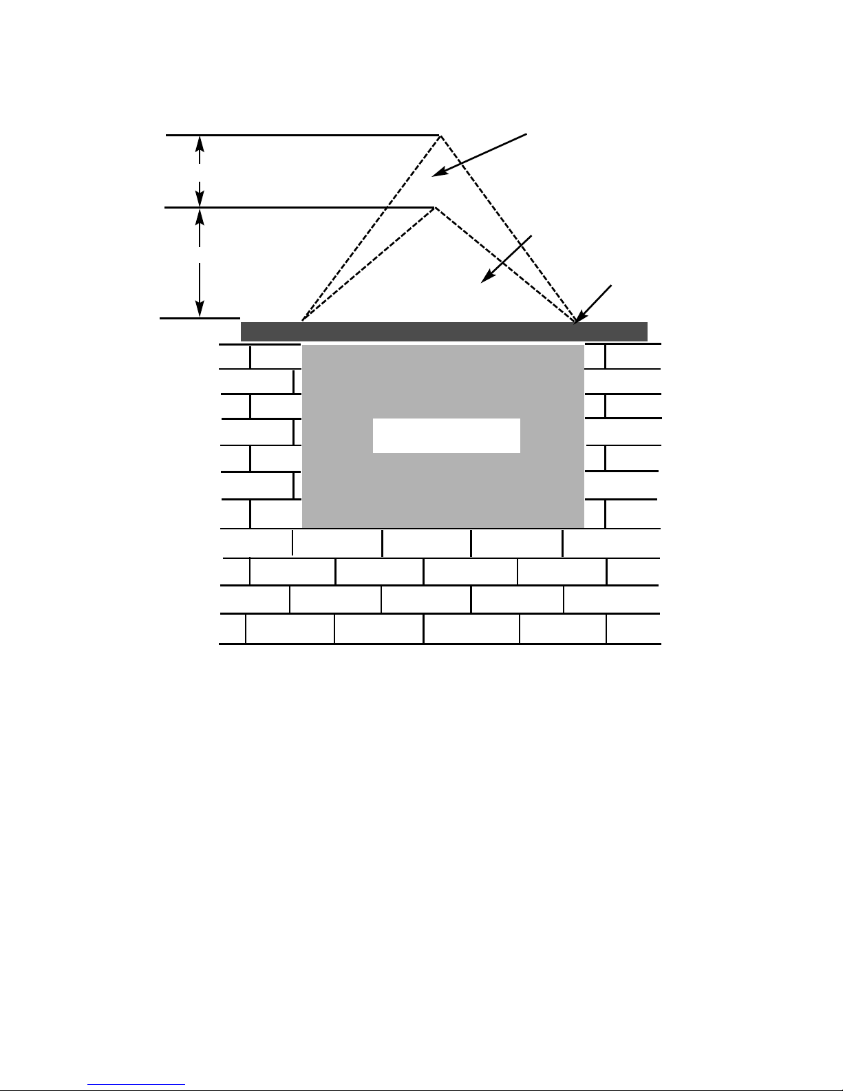
Fig. 7
The opening needs to be sufficient to accomodate the combustion chamber. To
support the wall above the opening, a suitable lintel must be inserted across the
top of the opening. The lintel could be either pre-cast concrete or steel - Catnic
CN52 or CN 46 could be used, depending upon the inner wall thickness. Before
proceeding with the installation of the fire, an assessment of the area immediately
above the fire is required, see Fig. 7 above. If there is no existing openings within
either triangle, proceed with forming the opening. However, if opening or beams
occur within either triangle, then you should seek specialist advice from a
structural engineer or consider relocating the proposed position of the firebox.
9
400mm interactive area
6
00mm load triangle
T
he Interactive Zone -
O
penings, beams or joists within
this area need to be assessed.
L
oad triangle - No beam or
opening permissible within this
area
Lintel
e.g. 750mm x 75mm
Proposed Opening in
Chimney Breast
Page 10
10
2.4 SECURING THE FIRE TO THE OPENING
a) The combustion chamber must be secured to the opening via the four
off screw and rawlplugs provided. Fig. 8 & 9 below shows the hole
centres in the mounting flanges of the combustion chamber.
Fig. 8
b) DO NOT SECURE THE COMBUSTION CHAMBER INTO THE
OPENING AT THIS POINT AS ACCESS WILL STILL BE REQUIRED
TO RUN THE GAS SUPPLY PIPEWORK AS DETAILED IN SECTION
2.5
Fig. 9
371mm
779mm
4 holes in combustion
chamber mounting flange
for securing to the opening
Page 11
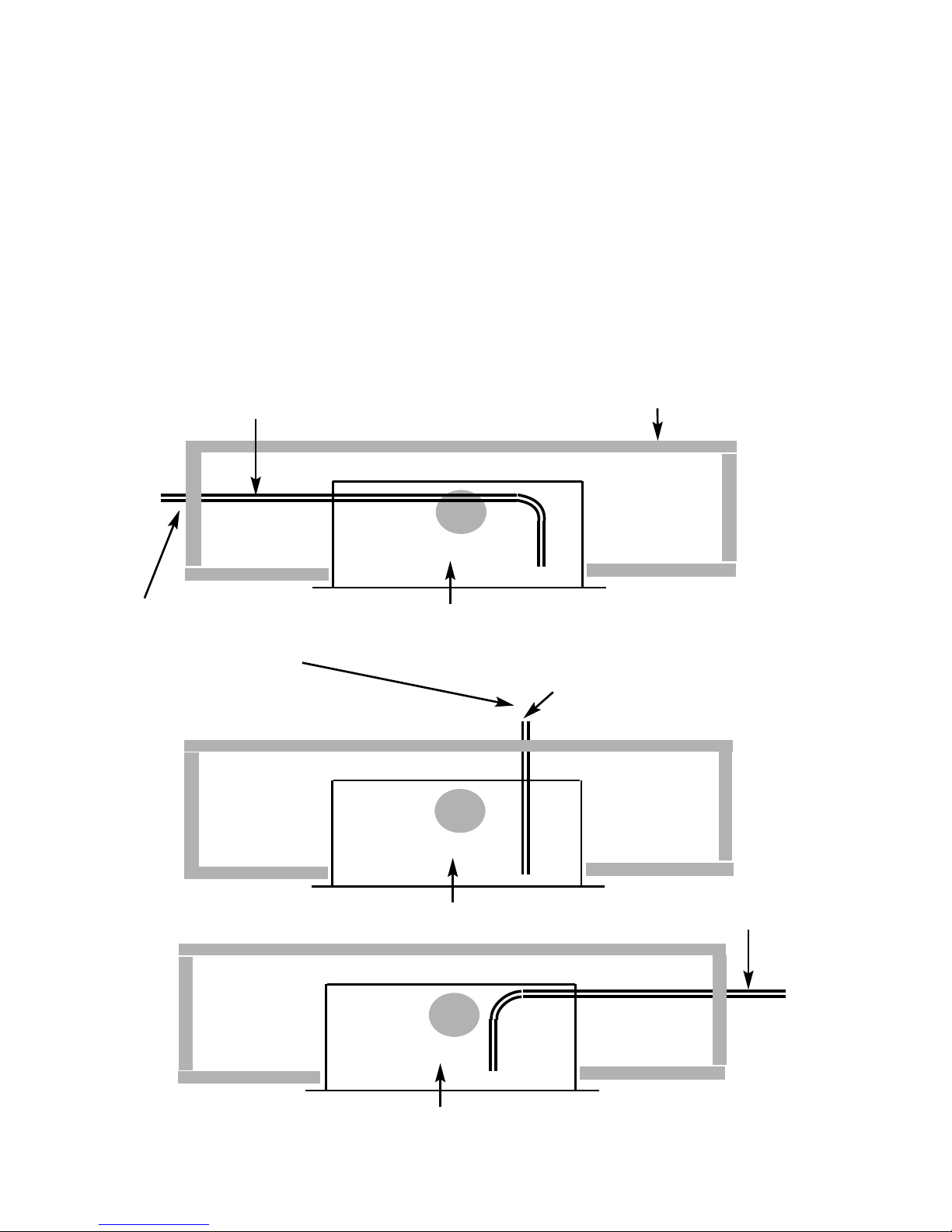
2.5 INSTALLATION OF THE GAS SUPPLY (INTO STUDDED WALL OR
EXISTING CHIMNEY BREAST)
Before installing the combustion chamber, decide from which side or if a rear
connection to the gas supply is required. Plan the pipe run to enter the below the
firebox from the left, right or rear and connect to the inlet elbow. See Fig. 10, 11 &
12 below.
Note : Before breaking into the gas supply a pressure drop test should be
carried out to establish that the existing pipework is sound. Always insert
the grommet into the entry point used (a sharp blow with a hammer or chisel
will be sufficient to knock out the opening selected in the firebox) and with
the grommet fitted cut with a sharp knife to allow the supply pipework to
pass through into the firebox.
11
Combustion Chamber
Gas Supply entering from L/H/S
Combustion Chamber
Gas Supply entering from Rear of Combustion Chamber
Outer
Cavity Wall or
rear face of
studwork
Ensure if bringing gas
supply through side or rear
of a chimney breast that the
pipe is sleeved and sealed
with a suitable flexible, non
setting compound
Fig. 10
Fig. 11
Combustion Chamber
Fig. 12
Gas Supply entering from R/H/S
Page 12
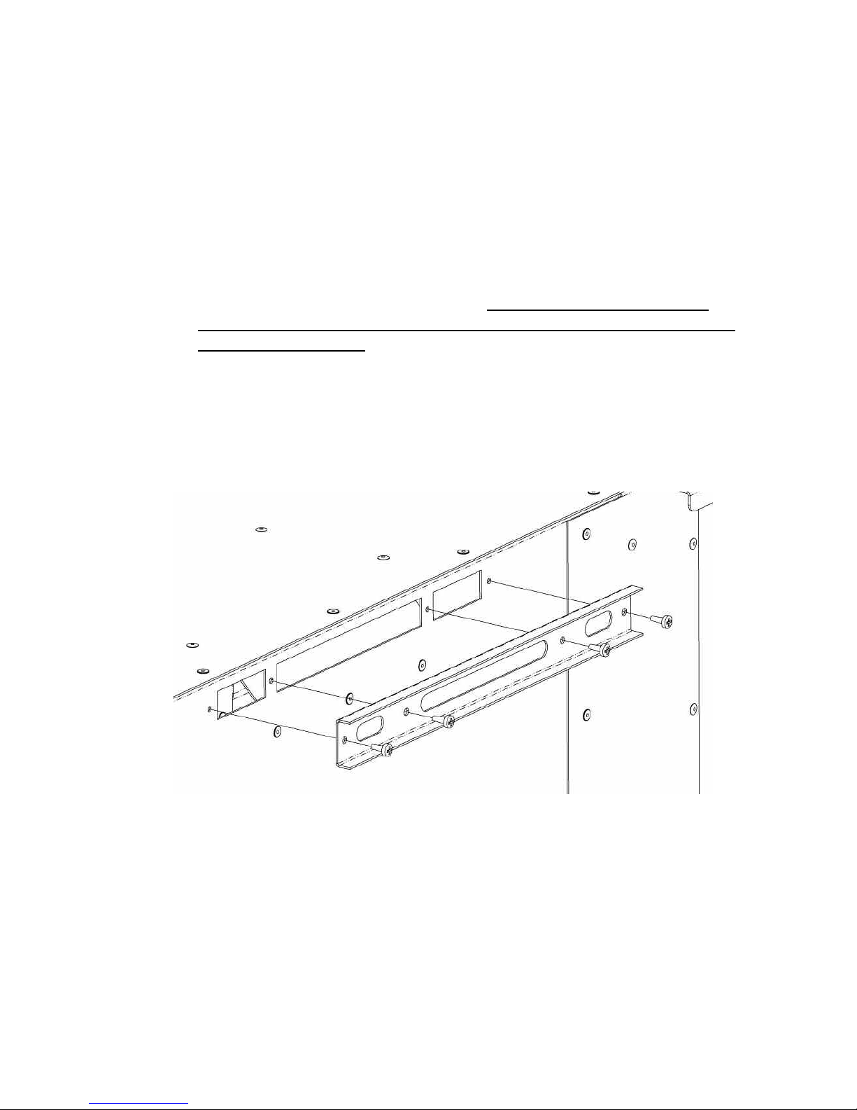
2.6 FITTING OF THE EFFICIENCY BAFFLE.
a) The product is supplied with an efficiency baffle to improve the
efficiency of the product when installed into Class 1 flues, of minimum
diameter 175mm / 7” or brick built 225mm x 225mm chimneys. The
minimum effective height of all flues must be 3 metres or above.
b) If the product is to be fitted into a Class 1 flue, it may be desirable to fit
the efficiency baffle.
c) If the product is fitted into a Class 2 flue of diameter 125mm / 5” then
the restrictor baffle must not be fitted. It should also be noted that if
fitting into a 125mm / 5” diameter flue that the minimum effective height
of the flue is 4 metres.
d) To fit the efficiency baffle (supplied in the loose items pack), use the 4
screws supplied to secure the baffle to the spigot on the rear of the
firebox as shown below in Fig. 13
Fig. 13
2.7 FITTING OF THE BATTERIES
a) The battery pack on SIT equipped models is at the front of the product
in the centre. Fit the 6 off AA batteries supplied.
b) The batteries on the Mertik Maxitrol equipped models are on the left
hand side, in the receiver unit. Slide the cover off and replace with 4 off
AA batteries.
12
Page 13
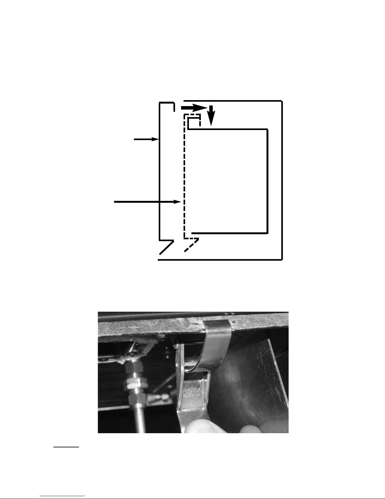
2.8 REMOVING / RE-FITTING THE GLASS FRAME ASSEMBLY
a) The glass frame is held in position by hooking the top flange over the
combustion chamber opening at the top as shown in Fig. 14 below.
Fig. 14
b) The assembly is then secured to the bottom of the combustion chamber
by the two hinge clamp brackets as shown below in Fig. 15. These
are clamped together to form the seal between the glass frame
assembly and the combustion chamber.
Fig. 15
NOTE :
Always ensure that a consistent seal between the combustion
chamber and the glass frame is achieved.
Glass Frame Assembly
locates over lip on top of
combustion chamber lid, and
drops onto flange as shown.
To remove, unclip base clips
as shown in Fig. 15 and lift
clear.
denotes correct
final position of
glass frame.
Combustion
Chamber
13
Page 14
SECTION 3
INSTALLATION OF FIRE
3.1 FITTING THE FUEL-BED LOGSET
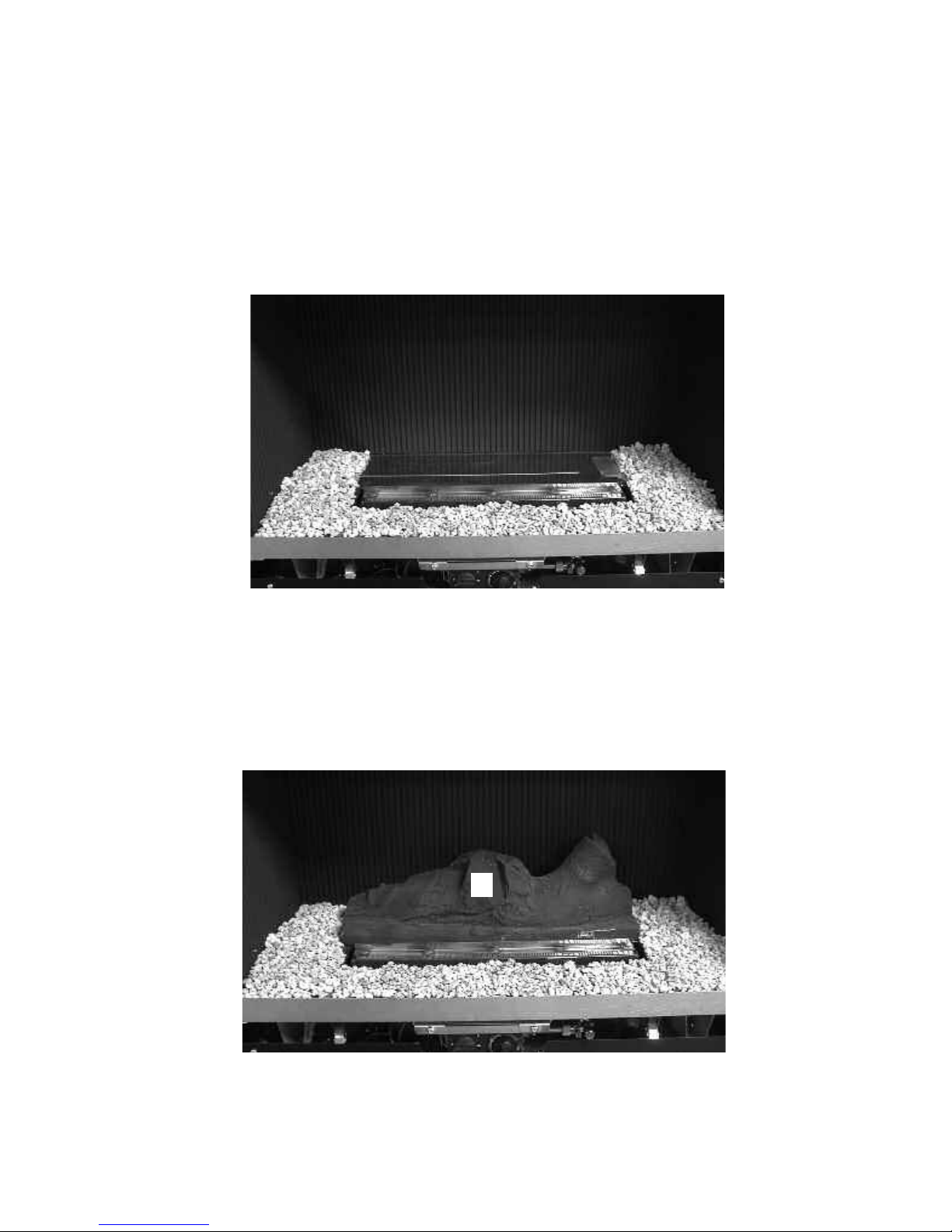
a) The gravel material should then be first layed around the base of the
combustion chamber as shown below in Fig. 16, leaving the rear
section as shown to allow the fitting of Log “A”
Fig. 16
b) Place the largest Log “A” centrally onto the fuel-bed support behind the
burner flame strip. Ensure that the fuel-bed Log “A” is located centrally
in the firebox, and that the front edge is parallel with the rear face of the
burner flame strip as shown below in Fig. 17.
Fig. 17
Fuel-bed
Log “A” to be
fitted behind
burner flame
strip
14
A
Page 15
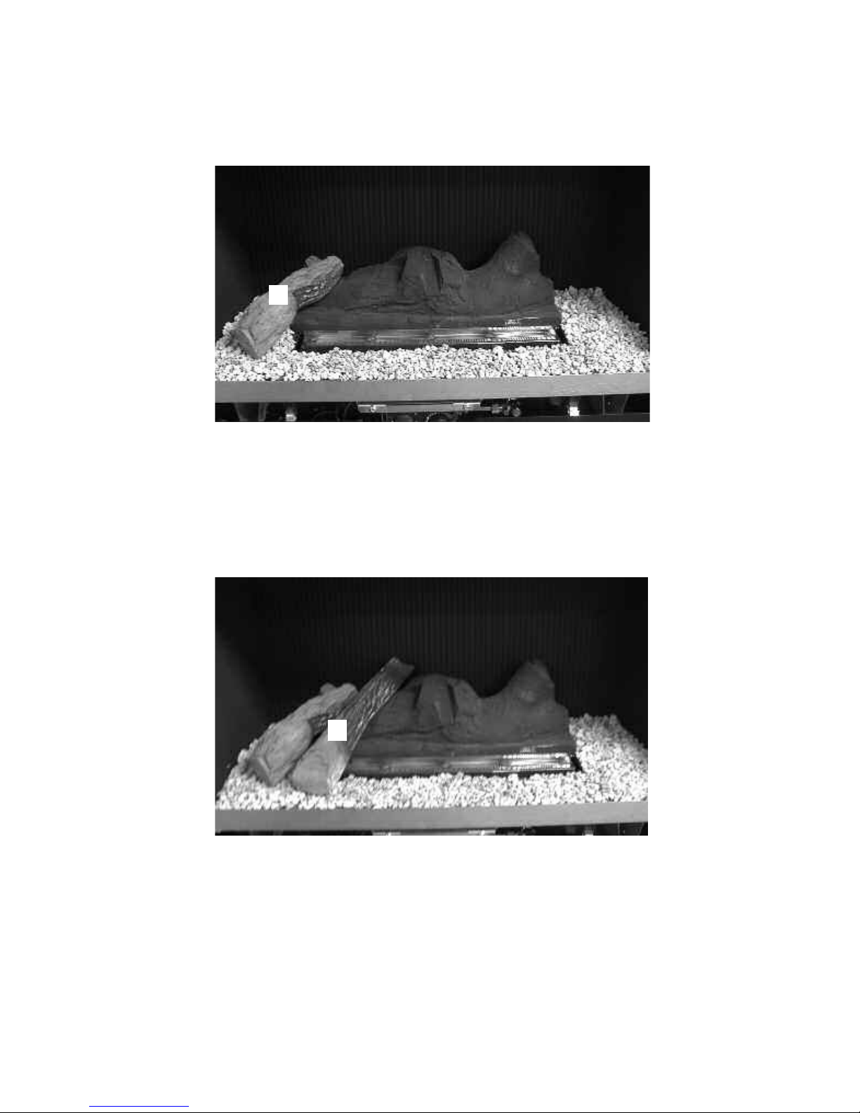
c) Fit Log “B” into position on left hand side of the fuel-bed base log “A”as
shown below in Fig. 18, using the groove in Log “A” as a guide for
placement.
Fig. 18
d) Fit Log “C” into position on left hand side of the fuel-bed base log “A”as
shown below in Fig. 19, using the groove in Log “A” as a guide for
placement.
Fig. 19
15
B
C
Page 16
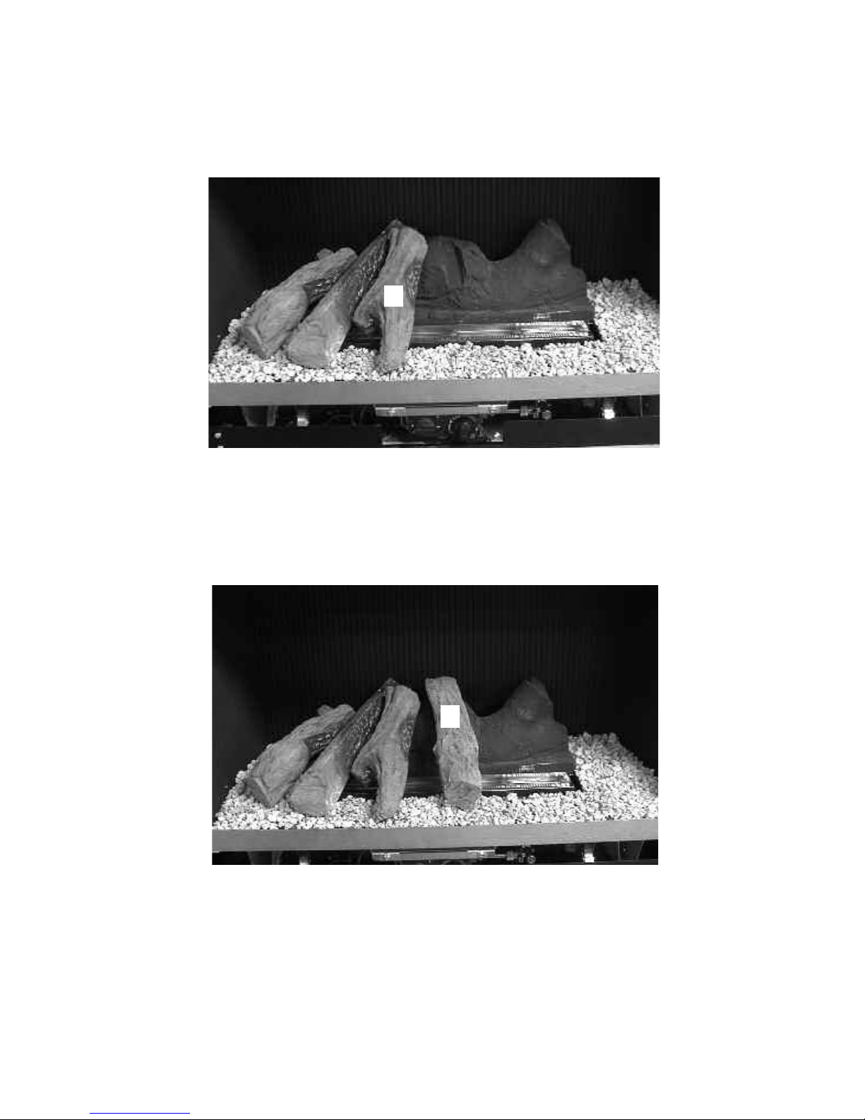
d) Fit Log “D” into position on left hand side of the fuel-bed base log “A”as
shown below in Fig. 20, using the groove in Log “A” as a guide for
placement.
Fig. 20
e) Fit Log “E” into position at centre of the fuel-bed base log “A”as
shown below in Fig. 21, using the groove in the centre of Log “A” as a
guide for placement.
Fig. 21
16
D
E
Page 17
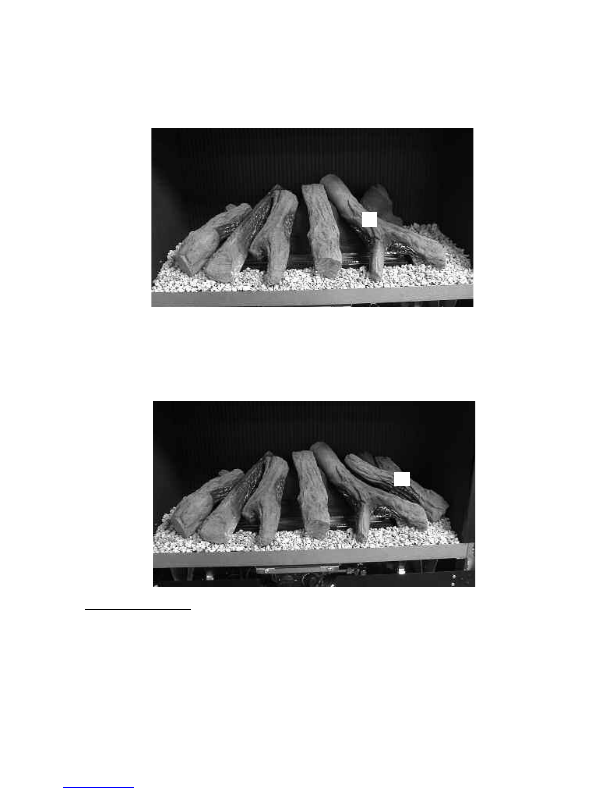
f) Fit Log “F” into position at right hand side of centre of the fuel-bed base
log “A”as shown below in Fig. 22, using the groove in Log “A” as a
guide for placement.
Fig. 22
g) Fit Log “G” into position at right hand side of the fuel-bed base log “A”as
shown below in Fig. 23, using the raised section in the base log as a
guide for position.
Fig. 23
IMPORTANT NOTE
HAVING FITTED THE GRAVEL MATERIAL IN THE BASE OF THE
COMBUSTION CHAMBER, ENSURE THAT NONE OF IT IS ON THE BURNER
FLAME STRIP OR IN THE PILOT ASSEMBLY. IF MATERIAL IS OBSERVED
VISUALLY ON THESE COMPONENTS, REMOVE THE FUEL-BED LOGSET,
REMOVE THE GRAVEL MATERIAL FROM THE BURNER AND OR PILOT AND
RE-FIT THE LOGS AS DETAILED IN SECTION 3.1 ABOVE.
17
F
G
Page 18

Warning : Use only the logs supplied with the fire. When replacing the
logs remove the old logs and discard them. Fit a complete set of logs of the
correct type. Do not fit additional logs or any logs other than a genuine
replacement set.
This appliance uses fuel effect pieces containing Refractory Ceramic Fibres
(R.C.F.), which are man-made vitreous silicate fibres. Excessive exposure to
these materials may cause temporary irritation to eyes, skin and respiratory
tract. Consequently, it makes sense to take care when handling these articles to ensure that the release of dust is kept to a minimum. To ensure that
the release of fibres from these R.C.F. articles is kept to a minimum, during
installation & servicing we recommend that you use a HEPA filtered vacuum
to remove any dust and soot accumulated in and around the fire, before and
after working on the fire. When replacing these articles we recommend that
the replaced items are not broken up, but are sealed within a heavy duty
polythene bag, clearly labelled as “RCF waste”. This is not classified as
“hazardous waste” and may be disposed of at a tipping site licensed for the
disposal of industrial waste. Protective clothing is not required when
handling these arrticles, but we do recommend you follow the normal
hygiene rules of not smoking, eating or drinking in the work area, and
always wash your hands before eating or
drinking.
This appliance does not contain any component manufactured from
asbestos or asbestos related products.
Refit the glass frame as detailed in section 2.7, then light the appliance as detailed
in section 3.4 / 3.5 as applicable.
3.2 MAKING THE GAS CONNECTION & CHECKING FOR GAS
TIGHTNESS
a) Before making the final gas connection, thoroughly purge the gas
supply pipework to remove all foreign matter, otherwise serious
damage may be caused to the gas control valve on the fire.
Failure to purge the gas supply will invalidate the guarantee.
b) The gas connection should be made to the appliance inlet elbow to
using 8mm rigid tubing.
c) Remove the pressure test point screw from the inlet elbow and fit a
manometer.
d) Turn on the main gas supply and carry out a gas tightness test.
18
Page 19

3.3 REMOVAL & RE-FITTING OF THE TRIM ASSEMBLY
a) The trim is supplied in 3 pieces, the rear panel, the front panel and the
stainless steel trim insert. Fix the rear panel to the wall with via the 4
screw holes with screws / rawlplugs. NOTE : The flange of the rear
panel must locate onto the base of the fire. If the stainless steel insert is
required (this is optional to fit) then push it into the front panel at this
stage.
Fig. 24
b) Fit the front panel and optional stainless steel insert (if required) onto
the product by hooking the retaining lugs into the slots on the
combustion chamber as shown above in Fig. 24
Retaining lugs on
rear face of trim hook
into the slots on the
combustion chamber
19
Front Panel
Rear Panel
Stainless Steel
Trim Insert
Page 20

3.4 LIGHTING THE APPLIANCE
Before attempting to light the appliance, please determine which remote
control system the product is fitted with. To determine this, check the
handset designs as shown below and follow the instructions on the
proceeding pages as necessary.
3.4.1 If fitted with the S.I.T. ACS2T System, the handset as shown below in
Fig. 25 will have been supplied. Please refer to section 3.4.3 to section
3.4.7.
Fig. 25
3.4.2 If fitted with the Mertik Maxitrol GV60 system, the handset as shown
below in Fig. 26 will have been supplied.Please refer to section 3.5.1 to
section 3.5.6
Fig. 26
20
Page 21

3.4.3 LIGHTING THE APPLIANCE - S.I.T. ACS2T REMOTE CONTROL
I
MPORTANT:IF THE BURNER IS EXTINGUISHED FOR ANY REASON YOU MUST ENSURE THAT
YOU WAIT A FULL FIVE MINUTES BEFORE ATTEMPTING TO RE-LIGHT THE FIRE.
The product is controlled by the remote handset supplied with the fire. Ensure the
3 off AAA batteries supplied in the loose items pack has been fitted to the handset
and the 6 off AA batteries have been fitted to the battery holder located in the
front of the fire before attempting to light it. There are 3 modes of operation of the
product, “MANUAL mode”, “TEMPERATURE mode” and “TIMER mode”.
3.4.4 Operation of the Fire in “MANUAL” mode
a) Firstly turn the handset on and light the fire by pressing and holding the
“ON” / “OFF” button on the remote handset for a minimum of 2 seconds
as shown below in Fig. 3, then releasing the button. The screen will
illuminate and the “MAN” mode will be illuminated as shown below in
Fig. 27. The 20 second ignition procedure is then initiated, the pilot and
main burner will light.
Fig. 27
b) The remote handset is now used to control all functions of the fire.
To turn the fire down or up incrementally, press the “DOWN” / “UP”
arrows as shown above in Fig. 27 and the gas input will reduce
accordingly. The flame level indicator will increase and decrease with
the input. When maximum input is reached, a “MAX” icon will appear
below the flame indicator in the top left hand corner. To put the fire into
“STANDBY” mode (where only the pilot remains lit) press the “ON” /
“OFF” button, the “PILOT” indicator will be shown and the main burner
will extinguish. See Fig. 28 overpage.
21
“Manual” Graphic
on Handset
Display
“UP” Arrow
“DOWN” Arrow
Flame Level
Indicator
“ON” / “OFF” Button
“MODE” Button
Page 22

Fig. 28
c) To turn the fire off, press and hold the “ON” / “OFF” button, this will
extinguish all flames including the pilot.
d) If is recommended that the handset is placed into locked mode
when not in use. To lock the handset, press and hold the “MODE”
button for a minimum of 5 seconds. To unlock the handset, press
and hold the “MODE” button for a minimum of 5 seconds.
22
“PILOT” Graphic on
Handset Display
Page 23

3.4.5 Operation of the Fire in “AUTOMATIC” mode
a) Firstly turn the handset on and light the fire by pressing and holding the
“ON” / “OFF” button on the remote handset for a minimum of 2 seconds
as shown in Fig. 3, section 3.4.4 a), Fig. 27
b) Press the “THERMOSTATIC” button on the handset below as shown in
Fig. 29, the handset will then switch to “AUTOMATIC” mode and the
“AUTO” icon will appear on the display as shown.
Fig. 29
c) The large digit temperature display shows the room tempertature that
the handset is sensing at the time. The small digit temperature display
shows the temperature that you wish to achieve in the room. See Fig.
29 above. To adjust, press the “UP” / “DOWN” arrow keys on the
handset. When “AUTO” mode is selected, the remote handset, by
means of an internal thermostat in the hnadset checks the difference in
temperature between the temperature you require and the room
ambient at a fixed time interval. Depending on the difference, the flame
level is modulated to maintain the required temperature. Once the
requested temperature is reached, the flame level is reduced to the
minimum level and remains in this state for a 2 minutes period, then it
will switch to standby mode (pilot only lit) and the “PILOT” icon will
appear on the display. As soon as the room temperature falls below the
set room temperature, the main burner will light and the fire will
modulate between the high and low settings.
“AUTO” Graphic on
Handset Display
“THERMOSTATIC”
Button
Room Temperature
Temperature Required
23
Page 24

3.4.6 Operation of the Fire in “PROGRAMME FUNCTION” mode
a) The handset is pre-programmed with ten off alternative settings to give
various options of timed, automatic useage. Please see table below for
the details of these 10 off pre-set functions.
b) To set the handset in “PROGRAMME FUNCTION” mode, please press
the “MODE” key as shown below in Fig. 30. This will then illuminate the
display and by using the “UP” and “DOWN” arrows on the handset you
can then toggle between the programs 1 to 10 or the “OFF” position to
disable the programmeable function.
Fig. 30
24
“MODE” Button
“PROGRAMME
P01” Graphic on
Handset Display
“UP” & “DOWN”
arrows - use to
toggle through
programe 1 to 10
Programme
Number
Time ON
(Monday to Friday)
Time OFF
(Monday to Friday)
Time ON
(Saturday / Sunday)
Time OFF
(Saturday / Sunday)
1 06:00 23:00 07:00 12:00
2 0
6:00 - 09:00 & 17:00 -
23:00
0
9:00 - 17:00 & 23:00
- 06:00
0
7:00
0
0:00
3 06:00 - 09:00, 12:00 -
15:00 & 17:00 - 23:00
09:00 - 12:00, 15:00 17:00 & 23:00 - 06:00
07:00 00:00
4 04:00 - 08:00, 11:00 -
14:00 & 17:00 - 22:00
08:00 - 11:00, 14:00 17:00 & 22:00 - 04:00
06:00 23:00
5 05:00 - 08:00, 12:00 -
14:00 & 17:00 - 23:00
08:00 - 12:00, 14:00 17:00 & 23:00 - 05:00
05:00 - 11:00
& 16:00 - 00:00
11:00 - 16:00
& 00:00 - 05:00
6 05:00 - 07:00 & 13:00 -
23:00
07:00 - 13:00 & 23:00
- 05:00
08:00 - 00:00 00:00 - 07:00
7 07:00 - 10:00, 13:00 -
15:00 & 18:00 - 23:00
10:00 - 13:00, 15:00 18:00 & 23:00 - 07:00
07:00 - 23:00 07:00 - 23:00
8 07:00 - 10:00 & 18:00 -
23:00
10:00 - 18:00 & 23:00
- 07:00
07:00 - 23:00 07:00 - 23:00
9 08:00 - 12:00 & 15:00 -
19:00
15:00 - 19:00 Off All Day Off All Day
10 18:00 - 00:00 00:00 - 18:00 07:00 - 23:00 23:00 - 06:00
Page 25

3.4.7 Low Battery Signal
a) When the batteries in the handset needs replacing, a small battery
symbol will appear on the handset.
b) Remove the cover on the rear of the handset and replace the 3 off AAA
batteries as necessary.
3.4.8 To Set the Time on the Remote Handset
a) Simultanelously press the “O” and “THERMOSTATIC” buttons
on the remote handset. The “CLOCK” icon will appear on the screen.
To set the hour use the “UP” and “DOWN” arrows.
b) Press the “O” button on the handset to switch to the minute setting and
To set the minute use the “UP” and “DOWN” arrows. When the time is
correctly set, either use the “O” button to exit or leave for 5 seconds and
the handset will automatically exit the “CLOCK” mode.
3.4.9 To SetoC oroF on the Handset Display
a) Press and hold the “THERMOSTATIC” button for a period of 5 seconds
and the display will change fromoC tooF and vice versa.
25
Page 26

3.5 LIGHTING THE APPLIANCE - MERTIK MAXITROL GV60 REMOTE
CONTROL
I
MPORTANT:IF THE BURNER IS EXTINGUISHED FOR ANY REASON YOU MUST ENSURE THAT
YOU WAIT A FULL FIVE MINUTES BEFORE ATTEMPTING TO RE-LIGHT THE FIRE.
The product is controlled by the remote handset supplied with the fire. Ensure the
9V battery as supplied in the loose items pack has been
fitted to the fire before attempting to light it and the 4 off AA batteries have been
fitted to the reciever unit, located next to the control valve at the L/H/S. There are
3 modes of operation of the product, “MANUAL mode”, “TEMPERATURE mode”
and “TIMER mode”.
3.5.1 Operation of the Fire in “MANUAL” mode
a) Locate the ON/OFF switch on the appliance, it is situated behind the
controls access cover at the bottom of the fire. Ensure that the on / off
switch on the valve is in the “ON” (1) position as shown below in Fig. 31
Fig. 31
b) The remote handset is now used to control all functions of the fire. To
light the fire, press the “UP” arrow and and “OFF” button simultateously.
as shown on Fig. 32 below. You will hear a click and the fire begins a
30 second ignition process. The pilot and main burner will light.
The appliance is now in “MANUAL mode” which will be shown via the
“MAN” graphic on the display of the handset as shown below in Fig. 32
Fig. 32
Manual Graphic
on Handset Display
Switch in the “ON” position
26
Page 27

c) With the product in “MANUAL” mode the fire can now be switched
between HIGH rate heat input and LOW rate heat input by pressing the
“DOWN” arrow on the handset. To reduce the flame height of the main
burner incrementally, press the arrow momentarily. To reduce the heat
input directly down to the minimum level, press and hold the “DOWN”
arrow on the handset. NOTE : At the lowest point the fire will go to
“STANDBY MODE”. In “STANDBY MODE” only the pilot remains lit.
See Fig. 33 below
Fig. 33
d) To turn the fire off, press the “OFF” button, this will extinguish all flames
including the pilot.
“SET” Button
“OFF” Button
“LARGE” Flame /
“UP” Arrow Button
“SMALL” Flame /
“DOWN” Arrow Button
27
Page 28

3.5.2 Operation of the Fire in “TEMPERATURE” mode
a) In order to change the mode of operation from “MANUAL” to
“TEMPERATURE”, press the “SET” button, the fire will then change
to either “DAY TEMP” (Fig. 34) mode or “NIGHT TEMP” mode (Fig 35).
To alternate between the 2, press the “SET” button. The display on
the handset will show the current temperature in the room.
NOTE : The “SET” button allows you to alternate between all modes of
operation :- “ MANUAL”, “DAY TEMP”, “NIGHT TEMP”, “TIMER” and
back to “MANUAL”. Alternatively, pressing either the “UP” or “DOWN”
arrow allows the unit to revert to “MANUAL” mode. Fire must be in
standby mode (pilot must be lit) for temperature mode to be used.
b) Within the “TEMPERATURE” mode there are options for either “DAY
TEMP” or “NIGHT TEMP”. These temperatures can be set
independently to allow a higher temperature to be maintained at night
than during the day, or if setting the same temperature for day and night
the fire will compensate for the generally cooler evening temperatures
and automatically increase the heat input level accordingly.
c) To set the temperature, ensure the handset is in “TEMPERATURE”
mode and then press the “SET” button until the “TEMP” display flashes
then let go. Proceed to set the desired temperature by pressing the
“UP” (large flame) or “DOWN” (small flame) arrows as necessary, then
press “OFF” to complete the process.
NOTE : Minimum temperature is 5oC, Maximum temperature is 30oC,
or minimum 41F to maximum 86F when in Fahrenheit mode.
d) Press the “OFF” button to stop the display flashing or wait to return to
“TEMPERATURE” mode. NOTE : If you set a temperature below the
current room temperature the fire will switch to standby mode (pilot
burner only) until the room has cooled to the temperature you have set
on the handset display.
e) If you would like the “NIGHT TEMP” to turn the fire off then decrease
the temperature until [----] is displayed.
“DAY TEMP”
Mode
“NIGHT TEMP”
Mode
Fig. 34
Fig. 35
28
Page 29

3.5.3 Operation of the Fire in “TIMER” mode
a) In order to change the mode of operation from “MANUAL” to
“TIMER”, press the “SET” button, the fire will then alternate
between the settings until the “TIMER” mode is displayed.
NOTE : The “SET” button allows you to alternate between all modes of
operation :- “ MANUAL”, “DAY TEMP”, “NIGHT TEMP”, “TIMER” and
back to “MANUAL”. Alternatively, pressing either the “UP” or “DOWN”
arrow allows the unit to revert to “MANUAL” mode. Fire must be in
standby mode (pilot must be lit) for temperature mode to be used.
b) Within the “TIMER” setting mode there are two programmable settings
you can make over a 24 hour period, namely P1 and P2. To set the
timer, ensure the handset is in “TIMER” mode as detailed in section a)
above.
c) To set the P1 timed start setting, press and hold the “SET” button until
the P1 (sun symbol is displayed as per Fig. 36 below) and the time
flashes. Set the hour by pressing the “UP” (large flame) and set the
minutes (in ten minute increments) by pressing the “DOWN” (small
flame) as necessary, then press “OFF” button to complete the process.
Repeat for the P1 (moon symbol is displayed as per Fig. 37 below) Set
the hour by pressing the “UP” (large flame) and set the minutes (in ten
minute increments) by pressing the “DOWN” (small flame) as
necessary, then press “OFF” button to complete the process.
d) To set the P2 timed setting, press the “SET” button until the “TIMER”
mode is displayed. Hold the “SET” button until the display flashes the
current time for P1. Press the “SET” button again to scroll past the
setting for P1 (sun) and P1 (moon). The time should now be flashing
on the handset. Set the hour by pressing the “UP” (large flame) and set
the minutes (in ten minute increments) by pressing the “DOWN” (small
flame) as necessary, then press “OFF” button to complete the process.
Fig. 36
Fig. 37
P1 with “Sun”
symbol
illuminated
P1 with
“Moon”
symbol
illuminated
29
Page 30

3.5.4 Low Battery Signal
a) When the battery in the handset needs replacing, “BATT” will be
displayed on the handset.
b) Remove the cover on the rear of the handset and replace the 9V battery
as necessary.
3.5.5 To Set the Time on the Remote Handset
a) Simultanelously press the “UP” (large flame) arrow and “DOWN” (small
flame) arrow buttons on the remote handset.
b) Press the “UP” (large flame) arrow to set the hour and the “DOWN”
(small flame) arrow to set the minutes.
3.5.6 To Set the
o
C / 24 Hour oroF / 12 Hour Clock
a) Press and hold the “OFF” and the “DOWN” (small flame) arrow buttons
on the handset simultaneously until the display changes fromoC tooF
and vice versa
30
Page 31

3.7 CHECKING FOR CLEARANCE OF COMBUSTION PRODUCTS
a) Close all doors and windows in the room.
b) Light the fire and allow to run for approximately 5 minutes on high
position.
c) After approximately 5 minutes hold a smoke match just inside and
below the centre of the lower front edge of the top of the fire as shown
in Fig. 38 below (It is recommended that a suitable smoke match
holder is used when checking for clearance of combustion products).
All smoke generated should be drawn back into the flue. If slight
spillage occurs or if in doubt, repeat the test after a further 5-10
minutes.
d) If spillage persists, the flue is not functioning correctly and a fault exists.
If, after investigation the fault cannot be traced and rectified, the fire
must be disconnected from the gas supply and expert advice obtained.
e) If there is an extractor fan fitted any where in the vicinity of the
appliance, the spillage test should be repeated with the fan running on
maximum and all interconnecting doors open.
f) After ensuring that the fire is safe to use it should be left on high
position to fully warm up. During this time a slight odour may be
noticed, this is due to the “newness” of the fire and will soon disappear.
Fig. 38
Smoke match position
10mm inside and down
from top face of central
slot
31
Page 32

SECTION 4
MAINTENANCE
Servicing Notes
Servicing should be carried out annually by a competent person such as a
GAS SAFE registered engineer. It is a condition of Verine Fires guarantee
schemes that this is carried out by a competent person i.e a GAS SAFE
registered Engineer in accordance with these servicing notes, and as a
condition of the guarantee the oxypilot must be changed.
The condition of the logs should be checked and if necessary the whole set
should be replaced with a genuine replacement set. The product must be
removed from the opening to check for debris accumulation if fitted without
a flue liner. See label attached to gas inlet elbow to see if appliance was
fitted without a flue liner when originally installed. After any servicing work
a gas tightness check must always be carried out.
4.1 Removing the burner assembly from the fire.
4.1.1 Isolate the gas supply.
4.1.2 Remove trim from the front of the fire, as shown in section 3.3
4.1.3 Remove the glass frame assembly from the fire, as shown in section
2.7
4.1.4 Remove the log set and loose gravel from the combustion chamber
base, taking care not to damage the logs.
4.1.5 Remove the access panel from the combustion chamber,
which is secured using six screws.
4.1.6 Remove the two burner retaining screws, 1 at each end of the burner.
4.1.7 Slide the burner off the main injector and remove from the product.
4.2 Removing the control valve sub assembly from the fire.
4.2.1 Isolate the gas supply.
4.2.1 Remove trim from the front of the fire, as shown in section 3.4
4.2.2 Disconnect the pipe to the bulkhead fitting on the valve and disconnect
the pipe on the valve which runs to the inlet elbow.
4.2.3 Loosen the pilot pipe, disconnect the ignition lead from the electrode
and disconnect the thermocouple from the pilot assembly.
32
Page 33

4.2.5 Remove the 2 off fixing screws which hold the valve to its mounting
bracket and lift the valve and its mounting plate away from the
combustion chamber.
4.2.6 Swap the valve (and reciever / control board on the SIT equipped
models) mounting plate onto the new valve and replace the fixings
holding it in position.
4.2.7 Re-assemble with pipes etc. in reverse order.
4.3 Removing the RF receiver (SIT ACS 2 T equipped models only)
4.3.1 Remove the control valve sub assembly as described in section 4.2
4.3.3 Disconnect the receiver unit from the control board and re-fit the new
receiver in its place.
4.4 Removing the Pilot Assembly
4.4.1 Isolate the gas supply
4.4.2 Remove trim from the front of the fire, as shown in section 3.3
4.4.3 Remove the glass frame assembly from the fire, as shown in section
2.7
4.4.4 Loosen the pilot pipe and disconnect the ignition lead from the
electrode.
4.4.5 Remove the two fixing screws which secure the pilot assembly to the
burner unit.
4.4.6 Remove the pilot assembly.
4.4.7 Re-assemble with a new pilot assembly, and carry out a gas
tightness test after re-assembly.
4.5 Replacing the Control Board (SIT ACS 2 T equipped models only)
4.5.1 Remove the control valve sub assembly as described in section 4.2
4.5.2 Disconnect all wiring looms from the control board.
4.5.3 Remove the 4 off screws which hold the control board to the mounting
plate.
33
Page 34

4.6 Replacing the Batteries in the Handset
4.6.1 Remove and re-fit the new 9V battery by removing the cover on the
back of the handset on the Mertik Maxitrol handset or 3 off AAA
batteries on the SIT unit.
Parts Shortlist
SIT Control Valve B-106790 ODS Pilot (Mertik) B-38930
SIT Handset B-129150 ODS Pilot (SIT) B-49710
SIT Receiver Unit B-129160 Glass Panel B-81190
SIT Control Board B-129140 Mertik Gas Valve B-92200
Complete Log Set B-109780 Mertik Control Board B-126400
Log “A” B-109700 & Handset
Log “B” B-109710
Log “C” B-109720
Log “D” B-109730
Log “E” B-109740
Log “F” B-109750
Log “G” B-109760
34
Page 35

SECTION FIVE - USER INSTRUCTIONS
5.1 INSTALLATION INFORMATION
CONDITIONS OF INSTALLATION
It is the law that all gas appliances are installed only by a competent (e.g. GAS
SAFE Registered) Installer, in accordance with the installation instructions and the
Gas Safety (Installation and Use) Regulations 1998 as amended. Failure to install
appliances correctly could lead to prosecution. It is in your own interest and that
of safety to comply with the law.
The fire may be fitted below a combustible shelf provided that the shelf is at least
300mm above the top of the appliance and the depth of the shelf does not exceed
150mm.
The fire may be installed below combustible shelves, which exceed 150mm deep
providing that the clearance above the fire is increased by 15mm for each 25mm
of additional overhang in excess of 150mm.
If this appliance is fitted directly on to a wall without the use of a fireplace or
surround, soft wall coverings such as wallpaper, blown vinyl etc. could be affected
by the heat and may discolour or scorch. This should be considered when
installing or decorating.
The Model number of this appliance is NPHL**RN and it is manufactured by :-
** denotes trim and colour variant
BFM Europe Ltd.
Trentham Lakes
Stoke-on-Trent
Staffordshire
ST4 4TJ
35
Page 36

5.2 ABOUT YOUR NEW FONTANA HE ROOM HEATER
The Verine Fontana High Efficiency log effect room heater incorporates a unique
and highly developed fuel bed which gives the realism of a loose log layout
combined with realistic flames and glow. The use of durable hard ceramic material
in the construction of the fuelbed components ensures long and trouble free
operation. When first using the new fire a slight smell may be noticed. This is due
to small deposits of oil on the firebox, but will soon disappear. Please take the
time to fully read these instructions as you will then be able to obtain the most
effective and safe operation of your fire.
DO NOT UNDER ANY CIRCUMSTANCES ATTEMPT TO USE THIS APPLIANCE
IF THE GLASS PANEL IS BROKEN OR HAS BEEN REMOVED.
IMPORTANT SAFETY INFORMATION
WARNING : This appliance has a hot surface and as with all heating
appliances a fireguard should be used for the protection of children, the
elderly and infirm. Fireguards should conform to B.S. 8423 : 2002
(Fireguards for use with gas heating appliances). Servicing should be
carried out annually by a competent person such as a GAS SAFE registered
engineer. It is a condition of BFM Europe Ltd. lifetime guarantees schemes
that this is carried out by a competent person i.e a GAS SAFE registered
Engineer.
The service should include visually checking the appliance, flue terminal and
fireplace for accumulation of debris around the firebox, and inspection of the
ceramic logs, replacing as necessary. Should debris be found upon the fuel-bed,
please contact a GAS SAFE registered installer. The condition of the ceramic log
set should be carefully checked and if necessary the whole unit should be
replaced with a genuine replacement set.
After any servicing work a gas tightness check must always be carried out.
Any debris or deposits should be removed from the log set from time to time. This
may be carried out by referring to the cleaning section as described later in this
book. Only the fuelbed components as supplied must be used and complete and
genuine replacements must be used. Always keep furniture and combustible
materials well clear of the fire and never dry clothing or items either on or near to
the fire. Never use aerosols or flammable cleaning products near to the fire when
it is in use.
36
Page 37

5.3 SPILLAGE MONITORING SYSTEM
This appliance is fitted with a spillage monitoring system which shuts down the fire
if the evacuation of combustion products from the fire is affected by a partially or
fully blocked flue pipe. If this system operates the fire will go out. If this occurs,
leave the fire for at least three minutes then follow the lighting procedure as
described in the previous section.
In the event of repeated operation a GAS SAFE registered gas installer must
be called to investigate and rectify the cause.
The fuel bed remains hot for a considerable period after use and sufficient
time should be allowed for the fire to cool before cleaning etc.
The fire must only be operated with the trim as supplied, in position.
37
Page 38

5.4 LIGHTING THE APPLIANCE
Before attempting to light the appliance, please determine which remote
control system the product is fitted with. To determine this, check the
handset designs as shown below and follow the instructions on the
proceeding pages as necessary.
5.4.1 If fitted with the S.I.T. ACS2T System, the handset as shown below in
Fig. 1 will have been supplied. Please refer to section 5.4.3 to section
5.4.9
Fig. 1
5.4.2 If fitted with the Mertik Maxitrol GV60 system, the handset as shown
below in Fig. 2 will have been supplied.Please refer to section 5.5.1 to
section 5.5.6
Fig. 2
38
Page 39

5.4.3 LIGHTING THE APPLIANCE - S.I.T. ACS2T REMOTE CONTROL
I
MPORTANT:IF THE BURNER IS EXTINGUISHED FOR ANY REASON YOU MUST ENSURE THAT
YOU WAIT A FULL FIVE MINUTES BEFORE ATTEMPTING TO RE-LIGHT THE FIRE.
The product is controlled by the remote handset supplied with the fire. Ensure the
3 off AAA batteries supplied in the loose items pack has been fitted to the handset
and the 6 off AA batteries have been fitted to the battery holder located in the
front of the fire before attempting to light it. There are 3 modes of operation of the
product, “MANUAL mode”, “TEMPERATURE mode” and “TIMER mode”.
5.4.4 Operation of the Fire in “MANUAL” mode
a) Firstly turn the handset on and light the fire by pressing and holding the
“ON” / “OFF” button on the remote handset for a minimum of 2 seconds
as shown below in Fig. 3, then releasing the button. The screen will
illuminate and the “MAN” mode will be illuminated as shown below in
Fig. 3. The 20 second ignition procedure is then initiated, the pilot and
main burner will light.
Fig. 3
b) The remote handset is now used to control all functions of the fire.
To turn the fire down or up incrementally, press the “DOWN” / “UP”
arrows as shown above in Fig. 3 and the gas input will reduce
accordingly. The flame level indicator will increase and decrease with
the input. When maximum input is reached, a “MAX” icon will appear
below the flame indicator in the top left hand corner. To put the fire into
“STANDBY” mode (where only the pilot remains lit) press the “ON” /
“OFF” button, the “PILOT” indicator will be shown and the main burner
will extinguish. See Fig. 4 overpage.
39
“Manual” Graphic
on Handset
Display
“UP” Arrow
“DOWN” Arrow
Flame Level
Indicator
“ON” / “OFF” Button
“MODE” Button
Page 40

Fig. 4
c) To turn the fire off, press and hold the “ON” / “OFF” button, this will
extinguish all flames including the pilot.
d) If is recommended that the handset is placed into locked mode
when not in use. To lock the handset, press and hold the “MODE”
button for a minimum of 5 seconds. To unlock the handset, press
and hold the “MODE” button for a minimum of 5 seconds.
“PILOT” Graphic on
Handset Display
40
Page 41

5.4.5 Operation of the Fire in “AUTOMATIC” mode
a) Firstly turn the handset on and light the fire by pressing and holding the
“ON” / “OFF” button on the remote handset for a minimum of 2 seconds
as shown in Fig. 3, section 5.4.4
b) Press the “THERMOSTATIC” button on the handset below as shown in
Fig. 5, the handset will then switch to “AUTOMATIC” mode and the
“AUTO” icon will appear on the display as shown.
Fig. 5
c) The large digit temperature display shows the room tempertature that
the handset is sensing at the time. The small digit temperature display
shows the temperature that you wish to achieve in the room. See Fig.
5 above. To adjust, press the “UP” / “DOWN” arrow keys on the
handset. When “AUTO” mode is selected, the remote handset, by
means of an internal thermostat in the hnadset checks the difference in
temperature between the temperature you require and the room
ambient at a fixed time interval. Depending on the difference, the flame
level is modulated to maintain the required temperature. Once the
requested temperature is reached, the flame level is reduced to the
minimum level and remains in this state for a 2 minutes period, then it
will switch to standby mode (pilot only lit) and the “PILOT” icon will
appear on the display. As soon as the room temperature falls below the
set room temperature, the main burner will light and the fire will
modulate between the high and low settings.
“AUTO” Graphic on
Handset Display
“THERMOSTATIC”
Button
Room Temperature
Temperature Required
41
Page 42

5.4.6 Operation of the Fire in “PROGRAMME FUNCTION” mode
a) The handset is pre-programmed with ten off alternative settings to give
various options of timed, automatic useage. Please see table below for
the details of these 10 off pre-set functions.
b) To set the handset in “PROGRAMME FUNCTION” mode, please press
the “MODE” key as shown below in Fig. 6. This will then illuminate the
display and by using the “UP” and “DOWN” arrows on the handset you
can then toggle between the programs 1 to 10 or the “OFF” position to
disable the programmeable function.
Fig. 6
P
rogramme
Number
T
ime ON
(Monday to Friday)
T
ime OFF
(Monday to Friday)
T
ime ON
(Saturday / Sunday)
T
ime OFF
(Saturday / Sunday)
1 06:00 23:00 07:00 12:00
2 06:00 - 09:00 & 17:00 -
23:00
09:00 - 17:00 & 23:00
- 06:00
07:00 00:00
3 06:00 - 09:00, 12:00 -
15:00 & 17:00 - 23:00
09:00 - 12:00, 15:00 17:00 & 23:00 - 06:00
07:00 00:00
4 04:00 - 08:00, 11:00 -
14:00 & 17:00 - 22:00
08:00 - 11:00, 14:00 17:00 & 22:00 - 04:00
06:00 23:00
5 05:00 - 08:00, 12:00 -
14:00 & 17:00 - 23:00
08:00 - 12:00, 14:00 17:00 & 23:00 - 05:00
05:00 - 11:00
& 16:00 - 00:00
11:00 - 16:00
& 00:00 - 05:00
6 05:00 - 07:00 & 13:00 -
23:00
07:00 - 13:00 & 23:00
- 05:00
08:00 - 00:00 00:00 - 07:00
7 07:00 - 10:00, 13:00 -
15:00 & 18:00 - 23:00
10:00 - 13:00, 15:00 18:00 & 23:00 - 07:00
07:00 - 23:00 07:00 - 23:00
8 07:00 - 10:00 & 18:00 -
23:00
10:00 - 18:00 & 23:00
- 07:00
07:00 - 23:00 07:00 - 23:00
9 08:00 - 12:00 & 15:00 -
19:00
15:00 - 19:00 Off All Day Off All Day
10 18:00 - 00:00 00:00 - 18:00 07:00 - 23:00 23:00 - 06:00
“MODE” Button
“PROGRAMME
P01” Graphic on
Handset Display
“UP” & “DOWN”
arrows - use to
toggle through
programe 1 to 10
42
Page 43

5.4.7 Low Battery Signal
a) When the batteries in the handset needs replacing, a small battery
symbol will appear on the handset.
b) Remove the cover on the rear of the handset and replace the 3 off AAA
batteries as necessary.
5.4.8 To Set the Time on the Remote Handset
a) Simultanelously press the “O” and “THERMOSTATIC” buttons
on the remote handset. The “CLOCK” icon will appear on the screen.
To set the hour use the “UP” and “DOWN” arrows.
b) Press the “O” button on the handset to switch to the minute setting and
To set the minute use the “UP” and “DOWN” arrows. When the time is
correctly set, either use the “O” button to exit or leave for 5 seconds and
the handset will automatically exit the “CLOCK” mode.
5.4.9 To SetoC oroF on the Handset Display
a) Press and hold the “THERMOSTATIC” button for a period of 5 seconds
and the display will change fromoC tooF and vice versa.
5.4.10 Turning the Product Off in the Unlikely event of a Remote Handset
Malfunction.
a) In the unlikely event of the remote control handset malfunctioning (or if
lost or broken) after the appliance has been turned on, the fire can be
turned off via the emergency shut off switch on the control panel.
b) To turn the product off, firstly remove the trim from the fire.
c) Press and hold the emergency shut off switch for up to sixty seconds.
d) When you release the emergency shut off switch, the fire will shutdown.
e) The appliance will now remain in the “off” position until activated by the
remote handset.
43
Page 44

5.5 LIGHTING THE APPLIANCE - MERTIK MAXITROL GV60 REMOTE
CONTROL
I
MPORTANT:IF THE BURNER IS EXTINGUISHED FOR ANY REASON YOU MUST ENSURE THAT
YOU WAIT A FULL FIVE MINUTES BEFORE ATTEMPTING TO RE-LIGHT THE FIRE.
The product is controlled by the remote handset supplied with the fire. Ensure the
9V battery as supplied in the loose items pack has been
fitted to the fire before attempting to light it and the 4 off AA batteries have been
fitted to the reciever unit, located next to the control valve at the L/H/S. There are
3 modes of operation of the product, “MANUAL mode”, “TEMPERATURE mode”
and “TIMER mode”.
5.5.1 Operation of the Fire in “MANUAL” mode
a) Locate the ON/OFF switch on the appliance, it is situated behind the
controls access cover at the bottom of the fire. Ensure that the on / off
switch on the valve is in the “ON” (1) position as shown below in Fig. 7
Fig. 7
b) The remote handset is now used to control all functions of the fire. To
light the fire, press the “UP” arrow and and “OFF” button simultateously.
as shown on Fig. 34 below. You will hear a click and the fire begins a
30 second ignition process. The pilot and main burner will light.
The appliance is now in “MANUAL mode” which will be shown via the
“MAN” graphic on the display of the handset as shown below in Fig. 8
Fig. 8
Manual Graphic
on Handset Display
Switch in the “ON” position
44
Page 45

c) With the product in “MANUAL” mode the fire can now be switched
between HIGH rate heat input and LOW rate heat input by pressing the
“DOWN” arrow on the handset. To reduce the flame height of the main
burner incrementally, press the arrow momentarily. To reduce the heat
input directly down to the minimum level, press and hold the “DOWN”
arrow on the handset. NOTE : At the lowest point the fire will go to
“STANDBY MODE”. In “STANDBY MODE” only the pilot remains lit.
See Fig. 9 below
Fig. 9
d) To turn the fire off, press the “OFF” button, this will extinguish all flames
including the pilot.
“SET” Button
“OFF” Button
“LARGE” Flame /
“UP” Arrow Button
“SMALL” Flame /
“DOWN” Arrow Button
45
Page 46

5.5.2 Operation of the Fire in “TEMPERATURE” mode
a) In order to change the mode of operation from “MANUAL” to
“TEMPERATURE”, press the “SET” button, the fire will then change
to either “DAY TEMP” (Fig. 10) mode or “NIGHT TEMP” mode (Fig 11).
To alternate between the 2, press the “SET” button. The display on
the handset will show the current temperature in the room.
NOTE : The “SET” button allows you to alternate between all modes of
operation :- “ MANUAL”, “DAY TEMP”, “NIGHT TEMP”, “TIMER” and
back to “MANUAL”. Alternatively, pressing either the “UP” or “DOWN”
arrow allows the unit to revert to “MANUAL” mode. Fire must be in
standby mode (pilot must be lit) for temperature mode to be used.
b) Within the “TEMPERATURE” mode there are options for either “DAY
TEMP” or “NIGHT TEMP”. These temperatures can be set
independently to allow a higher temperature to be maintained at night
than during the day, or if setting the same temperature for day and night
the fire will compensate for the generally cooler evening temperatures
and automatically increase the heat input level accordingly.
c) To set the temperature, ensure the handset is in “TEMPERATURE”
mode and then press the “SET” button until the “TEMP” display flashes
then let go. Proceed to set the desired temperature by pressing the
“UP” (large flame) or “DOWN” (small flame) arrows as necessary, then
press “OFF” to complete the process.
NOTE : Minimum temperature is 5oC, Maximum temperature is 30oC,
or minimum 41F to maximum 86F when in Fahrenheit mode.
d) Press the “OFF” button to stop the display flashing or wait to return to
“TEMPERATURE” mode. NOTE : If you set a temperature below the
current room temperature the fire will switch to standby mode (pilot
burner only) until the room has cooled to the temperature you have set
on the handset display.
e) If you would like the “NIGHT TEMP” to turn the fire off then decrease
the temperature until [----] is displayed.
“DAY TEMP”
Mode
“NIGHT TEMP”
Mode
Fig. 10
Fig. 11
46
Page 47

5.5.3 Operation of the Fire in “TIMER” mode
a) In order to change the mode of operation from “MANUAL” to
“TIMER”, press the “SET” button, the fire will then alternate
between the settings until the “TIMER” mode is displayed.
NOTE : The “SET” button allows you to alternate between all modes of
operation :- “ MANUAL”, “DAY TEMP”, “NIGHT TEMP”, “TIMER” and
back to “MANUAL”. Alternatively, pressing either the “UP” or “DOWN”
arrow allows the unit to revert to “MANUAL” mode. Fire must be in
standby mode (pilot must be lit) for temperature mode to be used.
b) Within the “TIMER” setting mode there are two programmable settings
you can make over a 24 hour period, namely P1 and P2. To set the
timer, ensure the handset is in “TIMER” mode as detailed in section a)
above.
c) To set the P1 timed start setting, press and hold the “SET” button until
the P1 (sun symbol is displayed as per Fig. 12 below) and the time
flashes. Set the hour by pressing the “UP” (large flame) and set the
minutes (in ten minute increments) by pressing the “DOWN” (small
flame) as necessary, then press “OFF” button to complete the process.
Repeat for the P1 (moon symbol is displayed as per Fig. 13 below) Set
the hour by pressing the “UP” (large flame) and set the minutes (in ten
minute increments) by pressing the “DOWN” (small flame) as
necessary, then press “OFF” button to complete the process.
d) To set the P2 timed setting, press the “SET” button until the “TIMER”
mode is displayed. Hold the “SET” button until the display flashes the
current time for P1. Press the “SET” button again to scroll past the
setting for P1 (sun) and P1 (moon). The time should now be flashing
on the handset. Set the hour by pressing the “UP” (large flame) and set
the minutes (in ten minute increments) by pressing the “DOWN” (small
flame) as necessary, then press “OFF” button to complete the process.
Fig. 12
Fig. 13
P1 with “Sun”
symbol
illuminated
P1 with
“Moon”
symbol
illuminated
47
Page 48

5.5.4 Low Battery Signal
a) When the battery in the handset needs replacing, “BATT” will be
displayed on the handset.
b) Remove the cover on the rear of the handset and replace the 9V battery
as necessary.
5.5.5 To Set the Time on the Remote Handset
a) Simultanelously press the “UP” (large flame) arrow and “DOWN” (small
flame) arrow buttons on the remote handset.
b) Press the “UP” (large flame) arrow to set the hour and the “DOWN”
(small flame) arrow to set the minutes.
5.5.6 To Set the
o
C / 24 Hour oroF / 12 Hour Clock
a) Press and hold the “OFF” and the “DOWN” (small flame) arrow buttons
on the handset simultaneously until the display changes fromoC tooF
and vice versa.
48
Page 49

5.6 CLEANING
WARNING : Before attempting any cleaning operation ensure that the fire has
been allowed to fully cool.
5.6.1 CLEANING THE TRIM AND PAINTED METAL PARTS
The extruded aluminimum trim that is supplied for use with this product must be
gently cleaned with a damp cloth only. Abrasive cleaners, chemical cleaning
agents or any type of polish must never be used as damage to the paint may
result.
5.6.2 CLEANING THE FUEL BED
We do not recommend cleaning the fuelbed other than at annual service intervals.
If carbon or soot accumulates on the logs, this should be removed by carefully
brushing the fuelbed using a soft brush. For instructions on how to remove the
glass panel please see page 55. The log set is made from a form of refractory
ceramic fibre and should be handled carefully to avoid generating dust, as
this may be harmful if inhaled. As with some fibrous materials, handling
fibrous materials without gloves could cause skin irritation.
The fuelbed should never be washed or exposed to any cleaning agents or
water.
Any damaged parts must be replaced by contacting your dealer, whose details
may be found on the BFM Europe website, address on the rear page. The log
set must only be replaced with a genuine replacement and the fire must never be
run with a different log set fitted.
The log set must be carefully reassembled as stated in pages 51-54.
5.6.3 CLEANING THE GLASS PANEL
To clean the glass panel, first ensure that the fire is cool, please note that the
glass panel will remain hot for a considerable period when the fire has been
switched off. Remove the glass frame assembly from the product as described
on page 55. Use a clean damp cloth and ceramic glass cleaner to remove any
stains or deposits frm the glass panel. Do not using scouring pads as this may
scratch the surface finish of the glass panel.
PLEASE NOTE
:- The glass will require cleaning periodically. Condensation
produced by the products of combustion will create marks on the inside face of the
glass panel.
49
Page 50

5.7 REMOVAL & RE-FITTING THE FUEL-BED LOGSET
a) The gravel material should then be first layed around the base of the
combustion chamber as shown below in Fig. 14, leaving the rear
section as shown to allow the fitting of Log “A”
Fig. 14
b) Place the largest Log “A” centrally onto the fuel-bed support behind the
burner flame strip. Ensure that the fuel-bed Log “A” is located centrally
in the firebox, and that the front edge is parallel with the rear face of the
burner flame strip as shown below in Fig. 15.
Fig. 15
Fuel-bed
Log “A” to be
fitted behind
burner flame
strip
A
50
Page 51

c) Fit Log “B” into position on left hand side of the fuel-bed base log “A”as
shown below in Fig. 16, using the groove in Log “A” as a guide for
placement.
Fig. 16
d) Fit Log “C” into position on left hand side of the fuel-bed base log “A”as
shown below in Fig. 17, using the groove in Log “A” as a guide for
placement.
Fig. 17
B
C
51
Page 52

d) Fit Log “D” into position on left hand side of the fuel-bed base log “A”as
shown below in Fig. 18, using the groove in Log “A” as a guide for
placement.
Fig. 18
e) Fit Log “E” into position at centre of the fuel-bed base log “A”as
shown below in Fig. 19, using the groove in the centre of Log “A” as a
guide for placement.
Fig. 19
52
D
E
Page 53

f) Fit Log “F” into position at right hand side of centre of the fuel-bed base
log “A”as shown below in Fig. 22, using the groove in Log “A” as a
guide for placement.
Fig. 22
g) Fit Log “G” into position at right hand side of the fuel-bed base log “A”as
shown below in Fig. 23, using the raised section in the base log as a
guide for position.
Fig. 23
Warning : Use only the logs supplied with the fire. When replacing the
logs remove the old logs and discard them. Fit a complete set of logs of the
correct type. Do not fit additional logs or any logs other than a genuine
replacement set.
53
F
G
Page 54

IMPORTANT NOTE
HAVING FITTED THE GRAVEL MATERIAL IN THE BASE OF THE
COMBUSTION CHAMBER, ENSURE THAT NONE OF IT IS ON THE BURNER
FLAME STRIP OR IN THE PILOT ASSEMBLY. IF MATERIAL IS OBSERVED
VISUALLY ON THESE COMPONENTS, REMOVE THE FUEL-BED LOGSET,
REMOVE THE GRAVEL MATERIAL FROM THE BURNER AND OR PILOT AND
RE-FIT THE LOGS AS DETAILED IN SECTION 5.7 ON THE PREVIOUS PAGES.
This appliance uses fuel effect pieces containing Refractory Ceramic Fibres
(R.C.F.), which are man-made vitreous silicate fibres. Excessive exposure to
these materials may cause temporary irritation to eyes, skin and respiratory
tract. Consequently, it makes sense to take care when handling these articles to ensure that the release of dust is kept to a minimum. To ensure that
the release of fibres from these R.C.F. articles is kept to a minimum, during
installation & servicing we recommend that you use a HEPA filtered vacuum
to remove any dust and soot accumulated in and around the fire, before and
after working on the fire. When replacing these articles we recommend that
the replaced items are not broken up, but are sealed within a heavy duty
polythene bag, clearly labelled as “RCF waste”. This is not classified as
“hazardous waste” and may be disposed of at a tipping site licensed for the
disposal of industrial waste. Protective clothing is not required when
handling these arrticles, but we do recommend you follow the normal
hygiene rules of not smoking, eating or drinking in the work area, and
always wash your hands before eating or
drinking.
This appliance does not contain any component manufactured from
asbestos or asbestos related products.
Refit the glass frame as detailed in section 5.8, then light the appliance as detailed
in section 5.4 / 5.5 as applicable.
54
Page 55

5.8 REMOVING / RE-FITTING THE GLASS FRAME ASSEMBLY
a) The glass frame is held in position by hooking the top flange over the
combustion chamber opening at the top as shown in Fig. 20 below.
Fig. 20
b) The assembly is then secured to the bottom of the combustion chamber
by the two hinge clamp brackets as shown below in Fig. 21. These
are clamped together to form the seal between the glass frame
assembly and the combustion chamber.
Fig. 21
G
lass Frame Assembly
locates over lip on top of
combustion chamber lid, and
drops onto flange as shown.
To remove, unclip base clips
as shown in Fig. 15 and lift
clear.
denotes correct
final position of
glass frame.
Combustion
Chamber
55
Page 56

5.9 REMOVAL & RE-FITTING OF THE TRIM ASSEMBLY
a) The trim is supplied in 3 pieces, the rear panel, the front panel and the
stainless steel trim insert. Fix the rear panel to the wall with via the 4
screw holes with screws / rawlplugs. NOTE : The flange of the rear
panel must locate onto the base of the fire. If the stainless steel insert is
required (this is optional to fit) then push it into the front panel at this
stage.
Fig. 22
b) Fit the front panel and optional stainless steel insert (if required) onto
the product by hooking the retaining lugs into the slots on the
combustion chamber as shown above in Fig. 22
IMPORTANT NOTE : The trim assembly of this product is
a working surface and as such will become hot in use.
Allow the product and trim to fully cool prior to
attempting to remove it.
56
Retaining lugs on
rear face of trim hook
into the slots on the
combustion chamber
Front Panel
Rear Panel
Stainless Steel
Trim Insert
Page 57

5.10 USER REPLACEABLE PARTS
The only user replaceable parts on this fire are the fuelbed / log form, and the
handset / ultrasonic receiver batteries, which may be replaced as described in the
below. Replacement of any other parts must be carried out by a
competent person such as a GAS SAFE registered gas installer.
The part numbers of the user replaceable parts are as follows, these are available
from specialist spares stockists whose details can be found on our web site,
www.bfm-europe.com, in the ‘stockist’ section.
Log Set B-109780
5.11 REPLACING THE BATTERIES IN THE HANDSET
a) Remove either the 1 off 9V battery or 3 off AAA batteries (dependent
upon which remote system is fitted to the product) by removing the
cover on the back of the handset.
b) Refit new battery and replace cover.
5.12 REPLACING THE BATTERIES IN THE FIRE
a) Remove the trim assembly as detailed in section 5.9
b) The battery pack on SIT equipped models is at the front of the product
in the centre. Replace with 6 off AA batteries. The batteries on the
Mertik Maxitrol equipped models are on the left hand side, in the
receiver unit. Slide the cover off and replace with 4 off AA batteries.
Due to our policy of continual improvement and development the exact
accuracy of descriptions and illustrations cannot be guaranteed
Part No. B-131650
Issue 2
BFM Europe Ltd.
Trentham Lakes
Stoke-on-Trent
Staffordshire
ST4 4TJ
www.bfm-europe.com
Telephone - General Enquiries : (01782) 339000
Telephone - Service : (0844) 7700169
 Loading...