

Verine Carmelo 1150 NHWV00RN NG, Carmelo 1150 NHWV00RP LPG Installation, User And Servicing Instructions
Page 1
Page 1 of 14
1. APPLIANCE DATA – SWITCHCRAFT & SENSOR REMOTE MODELS.
Carmelo 1150
Inset Fire
MODEL NUMBERS: NHWV00RN (NG) & NHWV00RP (LPG)
INSTALLATION, USER AND SERVICING INSTRUCTIONS
THIS APPLIANCE MEETS THE REQUIREMENTS OF THE EUROPEAN GAS DIRECTIVE
Model No. NHWV00RN for use with natural gas (G20) at a supply pressure of 20mbar.
Model No. NHWV00RP for use with propane (G31) at a supply pressure of 37mbar.
Both models are suitable for installation within G.B. / I.E.
THESE INSTRUCTIONS SHOULD BE RETAINED
BY THE USER FOR FUTURE REFERENCE
Page 2

Page 2 of 14
Installation & Service Record
Please ensure that installer completes the installation record below
INSTALLATION RECORD
Appliance Supplied by: …………………………....
Installation Date: ……………Serial No.:
….……...
Installed By: …………..…...CORGI No.: …..……
Signed by Installer: ………………………..…
RECORD OF 1st SERVICE
Serviced by: ………… CORGI No.:…………....
Service Date: …………… Signed: .…….…...
Comments: ………………………………………
………………………………………………………
………………………………………………………
RECORD OF 2nd SERVICE
Serviced by: ………… CORGI No.:…………....
Service Date: …………… Signed: ….…….…...
Comments: …………………………………………
…………………………………………………………
………………………………………………………..
RECORD OF 3rd SERVICE
Serviced by: ………… CORGI No.:…………....
Service Date: …………… Signed: .…….…...
Comments: ………………………………………
………………………………………………………
……………………………………………………….
RECORD OF 4th SERVICE
Serviced by: ………… CORGI No.:…………....
Service Date: …………… Signed: ….…….…...
Comments: ………………………………………
…………………………………………………………
………………………………………………………..
RECORD OF 5th SERVICE
Serviced by: ………… CORGI No.:…………....
Service Date: …………… Signed: .…….…...
Comments: ………………………………………
………………………………………………………
……………………………………………………
RECORD OF 6th SERVICE
Serviced by: ………… CORGI No.:…………....
Service Date: …………… Signed: ….…….…...
Comments: …………………………………………
…………………………………………………………
…………………………………………………………
RECORD OF 7th SERVICE
Serviced by: ………… CORGI No.:…………....
Service Date: …………… Signed: .…….…...
Comments: ………………………………………
………………………………………………………
………………………………………………………
RECORD OF 8th SERVICE
Serviced by: ………… CORGI No.:…………....
Service Date: …………… Signed: ….…….…...
Comments: …………………………………………
…………………………………………………………
………………………………………………………..
Page 3

Page 3 of 14
Contents
Page No.
Installation & Service Record 2
List of components 4
Appliance Data 4
GENERAL INSTALLATION REQUIREMENTS 4
Fitting the Appliance 4
Fitting the firebox 7
Filling the Burner 9
Placing of Decorative Refractory Shapes 9
COMMISSIONING 9
Check for spillage 9
Briefing the User 10
USERS GUIDE 10
Useful tips & recommendations 10
Operation of the fire 11
Lighting the Appliance 11
Cleaning the fire 12
SERVICING & MAINTENANCE 13
Spares Parts list 14
Important Notes – Please read before undertaking the
installation
1. This is not a “Do it yourself” product and it must be
installed by a competent person.
2. The chimney must be swept before the appliance is fitted.
3. The Installation Instructions must be adhered to without
exception.
Page 4
Page 4 of 14
Before fitting this appliance, ensure that the following components are enclosed
a) Upper & Lower Firebox complete with burner and controls.
b) Installation, Servicing & Users Instructions
c) 1 Packet of Burner fill granules
d) Roll of sealing tape
e) 1 Handset Control unit, 1 Power Supply Unit.
f) Flue Gather and fixings
g) 1 Pair Legs with adjustable feet.
h) (Optional) - Coal, Pebble, Log, or Driftwood Pack as selected.
APPLIANCE DATA
NHWV00RN NHWV00RP
GAS TYPE NATURAL GAS PROPANE
SUPPLY
PRESSURE
20mb 37mb
HEAT INPUT 14.3kW Gross 11.4kW Gross
INJECTOR SIZE Ø 3.0mm Ø 1.7mm
GAS CONNECTION 8 mm Compression
WEIGHT 45kg
GENERAL INSTALLATION REQUIREMENTS
Fitting the Appliance
1a United Kingdom; The law demands that all gas appliances are installed by a
qualified installer in accordance with the current GAS SAFETY (INSTALLATION
AND USE) REGULATIONS. The installation must comply with these installation
instructions and all relevant parts of Local and National Building Regulations or
Building Standards (Scotland) (Consolidation) Regulations and those relevant
recommendations of the following British Standards.
BS 5871: Parts 2 & 3, BS 8303, BS 5440: Parts 1 & 2, BS 1251, BS 6891
1b Eire; This appliance should be installed in accordance with the rules in force. The
installation must be carried out by a Competent Person and installed in accordance
with the current edition of I.S.813 ‘Domestic Gas Installations’ and the current
Building Regulations.
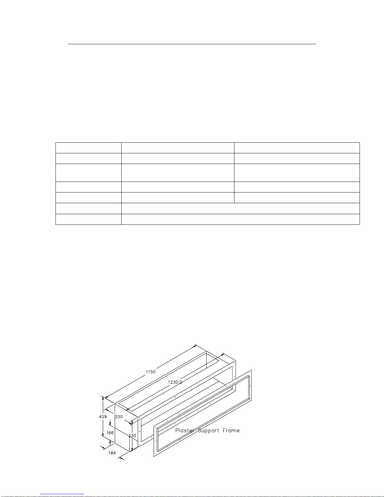
2 This appliance can be
fitted into fireplaces
FIGURE 1
Page 5
Page 5 of 14
which are large enough or can be altered to accept this appliance. The fireplace
should be made from or lined with non-combustible material. The appliance
dimensions are shown in Figure 1. If the fireplace has to be altered a lintel may be
required to support the masonry over the opening. Alternatively a false fire breast
may be constructed and the appliance connected to a prefabricated twin wall flue
system. This type of flue should be of at least 175mm diameter and T250 rating.
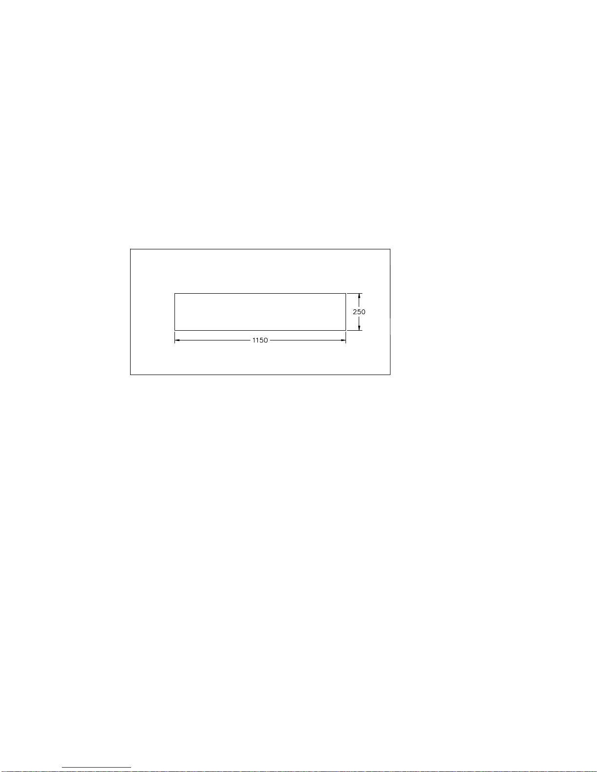
3 Wall Finishes
The appliance is supplied with an angled plaster support frame screwed to the front
flange of the firebox. This can be used when it is required that the wall is plastered
right up to the fire opening. This frame allows the plasterwork to finish with a clean
edge. If it is required that that the fire opening is be surrounded by decorative
stonework then this frame may be either left in position and the stonework butted
up to it or it may be removed and the fire opening framed by the finished stone.
Figure 2 gives the dimensions of the fire opening with the plaster support frame
removed. We recommend that wallpaper is not taken right up to the fire opening.
4 The Hearth
The hearth supporting the appliance within the fireplace must be made of a non
combustible material at least 12mm in thickness. In order to provide a tactile
warning to persons approaching the naked flames we strongly recommend that an
external hearth or a shelf mounted on the wall beneath the appliance opening so
that it projects at least 100mm both in front and either side of the appliance. This
hearth or shelf should also be made of a non combustible material and of at least
12mm in thickness and its upper surface should be at least 50mm above floor level.
BS 5871 Part 2 allows the installation of a fender at least 50mm high surrounding a
non combustible surface to satisfy this height requirement. If it is decided not to fit
a shelf or an external hearth the appliance must be installed so that the top of the
burner is at least 225mm above the finished floor level. Consideration should be
given to providing an equivalent level of safety with regard to the proximity of naked
flames as given by an external hearth.
5 The Chimney Flue
The chimney should be of the open-flue type and have a minimum cross sectional
dimension of not less than 175mm.
The flue must have a minimum effective height of 3 metres and have a temperature
rating of at least T250. If a proprietary metal twin wall gas flue is to be used the
appropriate appliance connector fitting will be required.
No restrictor plate or flue damper is permitted. Where a variable damper is fitted it
must be removed or locked in the open position.
The chimney must be swept before the appliance is fitted.
FIGURE 2
Page 6

Page 6 of 14
This appliance may be connected to an ‘Exhausto’ power flue system where no
suitable chimney is available. Details may obtained from Exhausto Ltd., Unit 3,
Lancaster Court, Coronation Road, Cressex Business Park, High Wycombe, HP12
3TD Tel; 01494 465166. The ‘Post Purge’ option must be selected when setting up
the system.
6 Gather
The gather supplied must be used to connect the appliance to the chimney. The
dimensions of the gather are given in Figure 3. Check the thickness of any masonry
plus the decorative infill panel, if used, against the distance shown between the rear
of the flange and the front of the gather. The gather should be installed, connected
to the flue and temporarily lodged in position before the firebox is finally placed in
position. After the firebox is properly positioned the gather can be drawn down to
the firebox by gripping the handles provided inside the gather and secured with
seven self tapping screws which pass through the top of the firebox into the gather.
Please note that the gather and firebox are not structural items and the flue should
be supported and not rest entirely on the gather.
7 Ventilation.
United Kingdom; The room containing the appliance must have a permanent air
vent with an effective open area of at least 100 cm2. The vent must be either direct
to outside air or to an adjacent room having a permanent vent of the same area.
Eire; Ventilation should be installed in accordance with the current edition of
I.S.813 ‘Domestic Gas Installations’ and the current Building Regulations.
8 Legs.
150mm tall legs with adjustable feet are supplied which can be used to raise the
appliance from an existing hearth. The legs are supplied loose and are fixed to the
lower firebox with two 8mm bolts. The legs do not have to be used. The appliance
may be raised using masonry blockwork if this is more convenient but allowance
must be made for the power supply unit which is suspended underneath the lower
firebox.
9 Power Supply Unit.
The remotely controlled gas valve fitted to this appliance operates via a 6 volt DC
power supply unit. The power supply unit supplied with the appliance must be
connected to a 220 – 240 volt AC mains supply. The power supply unit is supplied
already mounted to the plate that closes off the opening in the bottom of the lower
firebox. After the lower firebox has been installed the mains supply lead should be
lead to the opening in the lower firebox. The lead can then be plugged into the power
supply unit, the 6volt d.c. lead can be threaded through its grommet in the closure
FIGURE 3
Page 7

Page 7 of 14
plate and then the plate can be fixed in place with the four self tapping screws
supplied.
Fitting the Firebox
1 Check that the fireplace is of the correct size or has been modified to accept the
selected firebox. (See Figure 1).
2 It is recommended that, before proceeding further, a simple smoke test be performed
to check the condition of the chimney. Light a smoke match or a twist of rolled
paper, hold it within the fireplace opening and observe the behaviour of the smoke.
If it is being drawn into the chimney proceed with the installation. If not, pre-heat
the chimney over the period of a few minutes and recheck. If there is any doubt
about the soundness of the chimney a smoke pellet should be used after preheating
the flue and if smoke still fails to clear, further investigation of the chimney is
required and the appliance MUST NOT be fitted until any fault has been rectified.
3 Clear the recess of any loose material. Ensure that the base on which the lower
firebox will stand is level and that the base of the recess and the hearth are
horizontal and non-combustible. If the fire opening is to be elevated the base under
the firebox will have to be raised to suit and the masonry above the firebox altered to
accommodate the gather.
4 The gas supply should be routed from the meter or cylinder to a point convenient to
the fireplace. Ensure that there is a mains socket near the fireplace for the power
supply to the appliance.
Natural Gas Model.
Due to the high gas input of this model we recommend that large diameter gas
supply pipe (15 or 22mm) is taken right into the fireplace. The last section should
be of 8mm diameter to connect to the burner with the nut and olive provided.
Please remember that no soldered joints are allowed within the burner unit itself.
When commissioning the appliance ensure that the inlet pressure at the pressure
test point on the appliance is 20mbar +/- 1mbar.
5 As stated previously the firebox is made in two sections, the lower part which
houses the gas control and the upper part which is the actual firebox and provides
the containment of the flame and products of combustion. See Figure 4.
6 Before starting to install the firebox remove the grill, the main burner, the heatshield
and the control mount from the lower firebox. Grommeted gas entry holes are set
FIGURE 4
Page 8

Page 8 of 14
into the rear and bottom of the lower firebox.
7 Slide the firebox into the opening. If a decorative infill panel is going to be used and
is not yet in place make sure that the firebox flange clears the front face of the fire
opening by the thickness of the infill panel. Ensure that the flue opening is
unobstructed and gives a clear passage for the products of combustion to the flue.
The firebox can now be fixed in position using screws and wall plugs to the hearth
and rear wall of the fire opening through the slotted holes in the bottom and rear of
the lower part of the firebox. Do not fully tighten these screws at this time.
8 At this point the installation may be easier if the top part of the firebox is removed
from the bottom to give better access to install the gas supply.
9 Temporarily place the control mount in the lower part of the firebox and run the gas
supply through one of the grommeted holes at the rear or bottom of the lower firebox
and connect it to the gas inlet fitting. This fitting accepts 8mm diameter tubing.
Prior in connecting the gas supply to the appliance it is important to blow out the
supply pipe to clear any of the debris that may be present and which could cause a
blockage in the control valve or pilot. Provision will have to be made to pass the pipe
through the masonry of the fireplace. Care must be taken to sleeve the supply pipe
when passing through the masonry. Exposed pipe within the fire opening should be
wrapped, painted with bituminous paint or factory sheathed. Disconnect the gas
supply and remove the control mount.
10 The space in front of the lower part of the firebox can be filled with masonry and
made good or an infill panel fitted. Slide the upper part of the firebox into position
and fix to the lower part with eight plain self tapping screws.
11 Replace the control mount in position making sure that the holes locate over the
studs in the base of the firebox. As the control mount is lifted into position the lead
from the power supply unit should be plugged into the electronic box under the
control mount. the socket for the 6v DC supply is located on the side of the control
next to the gas control valve. Re-connect the gas supply and plug the lead from the
power supply unit into the mains.
12 Replace the heat shield. Place the burner in position ensuring that the mixing tube
locates in its hole in the burner mount over the injector. Carefully place the infill
grill in position with the locating tabs engaging with the slots in the front lower part
of the firebox and fix in place at the back of the box with the four self tapping screws
provided. Since the infill grill locates and secures the main burner, the burner
position may have to be adjusted slightly before the grill will lay flat.
13 Gas Soundness Check
Once the gas supply is connected, all joints must be checked for gas soundness.
Note: It is permissible to light the fire FOR SHORT PERIODS ONLY when the
burner has not been filled with the loose infill. It is easier to perform these checks if
the burner is temporarily placed in position without re-placing the grill and heat
shield as the tube from the manometer can pass in front of the burner. Please note
that the flames from the burner ports will not all be of equal length.
Page 9

Page 9 of 14
Filling the Burner
WARNING
This product uses fuel effect pieces containing Refractory Ceramic Fibre (RCF),
which are man-made vitreous silicate fibres along with fibrous glass and
mineral wool. Excessive exposure to these materials may cause temporary
irritation to eyes, skin and respiratory tract; consequently, it makes sense to
take care when handling these articles to ensure that the release of dust is
kept to a minimum.
CAUTION All the ceramic components are fragile and should be handled with
care.
1 Fill the burner tray level to the top using the granules of ceramic gravel provided
making sure that the burner ports between the flame guides down the centre are left
completely clear. When new, the burner is supplied with a piece of tape covering the
gap between the flame guides. After the burner tray has been filled the tape can be
removed. If the tape has already been removed a strip of corrugated cardboard cut
from the carton can be placed between the flame guides and will do the same job.
The fire will not function correctly without these granules in place.
Placing of Decorative Refractory Shapes
1 Decorative fuel packs made from refractory material may be placed on top of the
ceramic gravel to increase the decorative effect. Fuels should not be placed on the
infill grill except for the ends of logs and driftwood.
The following packs may be used;
Coal Pack – containing 30 medium random coals
Pebble Pack – containing 30 large pebbles
Log Pack – containing 9 refractory logs
Driftwood Pack – containing 11 pieces refractory driftwood
2 The refractory pieces may be arranged as desired. If the objects on the fire-bed
become excessively covered in soot they should be removed from the fire or placed in
another position.
COMMISSIONING
Before attempting to light the appliance the gas supply must be turned on by
removing the cap from the isolator fitting and unscrewing the plug all the way out.
(This has to be done before the burner placed into position and the infill grill fixed
down). Replace the cap making sure that the tab engages with the slot in the top of
the plug. Tighten the cap securely. Before attempting to light the appliance ensure
that the power supply to the appliance is switched on at the mains and that the
appliance ON/FF switch (located behind the infra red sensor) is switched to the ON
position (the symbol I should be pressed down). Light the appliance in accordance
with the instructions in the lighting section within the Users Guide.
Check for spillage
1 Before briefing the customer on how to use the appliance, a spillage test must be
carried out. The following procedure must be followed.
2 Close all doors and windows in the room or space containing the appliance.
3 Light a smoke match and pass completely along and just inside the inner flange that
is just forward of the opening to the chimney. A visual check should ascertain that
all the smoke generated is drawn into the firebox and up the flue.
4 If there is evidence of spillage, the flue should be heated for a period of 5 to 10
minutes and the test repeated.
5 If there is still evidence of spillage the appliance should turned be off and the
chimney and ventilation investigated. The appliance must not be left in an
operational state until the faults have been identified and corrected.
Page 10

Page 10 of 14
Briefing the User
1 Demonstrate the full operation of the appliance to the customer, referring them
specifically to the ceramic granules, any decorative ceramic shapes and the removal
of soot as described in these instructions.
2 Inform the customer that all cleaning procedures should be carried out only when
the appliance is cold.
3 Leave these instructions with the customer.
4 Advise the importance of having the appliance serviced and the chimney checked for
clearance of combustion products on an annual basis.
USERS GUIDE
Useful tips & recommendations
Once your fire has been fitted, the following recommendations are made to ensure
you enjoy the best results from your purchase;
1 The installation of this appliance must have been carried out by a qualified installer
and in accordance with the requirements of the Gas Safety (Installation & Use)
Regulations
2 The chimney must be swept before the appliance is installed and checked annually
to ensure continued clearance of combustion products and that there is no
excessive build-up of soot.
3 As with any fire, certain components will become hot in use. Care should be
exercised when approaching the appliance when it is hot. We also recommend that
a fireguard, conforming to BS 6539 or BS 6778, be fitted for the protection of young
children, the elderly or infirm.
4 When new any ceramic components may produce a slight odour, but this will
completely vanish after a few hours of use.
5 Handle any ceramic components gently (See warning on Page 9). They are fragile. A
soft brush can be used to clean them of any excess soot. UNDER NO
CIRCUMSTANCES should they be washed.
6 Never throw cigarette ends or other foreign matter onto the fire.
7 Never leave the house unattended, with the fire alight, for long periods.
8 Check periodically that any purpose-made ventilation is free from obstruction.
9 To obtain the best results from your fire we recommend that it be serviced annually.
10 These instructions are provided to assist you to operate the fire correctly and should
be kept in a safe place.
11 This appliance is intended for decorative purposes.
12 This appliance is fitted with a flue blockage device that will shut off the appliance in
the event of abnormal flue conditions. This device is NOT a substitute for an
independently mounted carbon monoxide detector.
Page 11

Page 11 of 14
Operation of the fire
1 It should be noted that your fire is fitted with a Flame Supervision Device, which
cuts off the gas supply to your fire if, for any reason the pilot light is extinguished.
It also monitors constantly the oxygen in the room. The pilot flame heats the
thermocouple probe and allows gas to flow to the burners. If due to pilot failure, the
thermocouple cools, no gas will flow to the main burner. If the fire is turned off or
the flames go out, wait for AT LEAST 3 MINUTES before attempting to relight the
fire.
2 Before attempting to light the appliance ensure that the power supply to the
appliance is switched on at the mains and that the appliance ON/OFF switch
(located behind the infra red sensor and in front of the pilot burner) is switched to
the ON position (the symbol I should be pressed down).
Lighting the Appliance
1 Fitting the Battery to the Handset
Before using the appliance remove the access cover in the rear of the handset and
insert a 9 volt PP3 size battery. Connect the battery by pushing the connector on to the
terminals. Make sure the battery is connected correctly. Replace the access cover.
2 Using the Handset
When using the handset make sure that it is pointed at the infrared signal receiver
located just in front of the pilot burner at the right hand end of the main burner (the
small black pad )See Figure 5 Unlike a TV control the fire does not react to a quick
press on the button on the handset control. The buttons must be pressed and held
until the control box under the burner acknowledges the signal by emitting a 'beep'
sound (this can take two or three seconds). When the handset is emitting a signal
the red LED at the top of the control will light.
3 Lighting the Fire
To light the fire press the SMALL BUTTON and the UP BUTTON buttons together on
the handset until the fire control box answers with a 'beep'. The fire will go through
its start - up procedure by lighting first the pilot burner and then the main burner
on high fire. This procedure takes about 30 seconds. During this process the fire will
emit a regular series of ‘beeps’. If the fire does not light or there is no reaction when
the two buttons are pressed, press the OFF button to 're-set' the control and try
again.
FIGURE
5
Page 12

Page 12 of 14
4 Adjusting the Flame Height
To lower the flame height press and hold the DOWN BUTTON until the flame is at
the desired height. To turn the main burner off and just leave the pilot burner alight
continue to press and hold the down button until the main burner does out. To relight the main burner press and hold the SMALL BUTTON and UP BUTTON together
until the flame is at the desired height.
5 Turning the Fire OFF
To turn the fire off but leave the pilot burner alight press the DOWN BUTTON until
the main burner does out. To turn the fire completely off press the OFF button.
Manual Off Facility
If, whilst the fire is alight, the handset control is lost or its battery becomes
discharged the fire can be turned off by switching the appliance ON/OFF switch
(located just behind the signal receiver which is situated just in front of the right
hand side of the main burner) to the OFF position which is indicated by the symbol
O. Caution should be exercised as this switch is situated quite close to the pilot
flame. Switch back to the ON position to allow the appliance to be re-lit when
required.
Cleaning the fire
1 Ensure that the fire is cold before undertaking any cleaning. Remember that heat is
retained for some time after the fire is switched off. In normal use your fire requires
only minimal cleaning. Some soot may form on any ceramic pieces placed in the
flames but this is generally harmless unless an excessive amount is deposited.
2 If large pieces of debris are found in the fire, sufficient to alter the appearance or
operation of the appliance, the chimney / flue should be inspected and the
appliance serviced before further use.
In any event, the chimney should be checked annually to ensure continued clearance of the
combustion products and that there is no excessive build-up of soot.
Page 13

Page 13 of 14
SERVICE AND MAINTENANCE
WARNING
This product may use fuel effect pieces containing Refractory Ceramic Fibre
(RCF). This material contains man-made vitreous silicate fibres along with
fibrous glass and mineral wool. Excessive exposure to these materials may
cause temporary irritation to eyes, skin and respiratory tract; consequently, it
makes sense to take care when handling these articles to ensure that the
release of dust is kept to a minimum.
The appliance should be serviced at least once a year by a CORGI registered
engineer. This is the basic procedure.
1 Any refractory shapes should be taken off the fire and shaken to remove any debris
but should only be cleaned if absolutely necessary. This should be done by gently
brushing with a soft brush in a direction away from the person and any persons
nearby. This operation should be performed outside facing downwind. A vacuum
cleaner must not be used for this purpose.
2 Undo the four screws holding the infill grill in position a lift it out of the firebox. Lift
the main burner and the heat shield out of the firebox. The gas supply should be
turned off at the combination pressure test point and isolator fitting. Disconnect the
control mount from the gas supply and lift it out of the lower firebox after
unplugging the lead from the power supply unit from the electronic control box.
3 Empty the ceramic gravel from the burner on to a clean surface and thoroughly
clean the burner ports.
4 The pilot burner fitted is an oxygen depletion pilot burner and is the primary safety
device on the appliance. It must therefore be replaced annually. After changing the
pilot burner operate the spark generator and observe that the spark is satisfactory.
5 Lay the control mount assembly on a flat surface and remove, clean and replace the
main injector.
6 Any soot or debris should be removed from the fireplace and flue. The flue should be
inspected for soundness and a smoke test performed as described in the fitting
section to check the condition of the flue.
7 Replace the control mount in position making sure that the holes locate over the
studs in the base of the firebox. Re-connect the gas supply and the lead from the
power supply unit. Place the heat shield in position. Place the burner in position
ensuring that the mixing tube locates in its hole in the burner mount over the
injector. Carefully place the infill grill in position with locating tabs engaging with
the slots in the front lower part of the firebox and fix in place with the four screws
removed in paragraph 2. Refill the burner with the ceramic gravel making sure that
the burner ports between the flame guides down the centre are left completely clear.
Inserting a piece of corrugated cardboard between the flame guides will help keep
the burner ports clear during this operation. Replace any refractory shapes that
were in place on the burner.
8 AFTER REFITTING THE APPLIANCE CHECK FOR GAS SOUNDNESS AT ALL GAS
JOINTS AND TEST FOR SPILLAGE.
Handset Battery Replacement
9 The handset is powered by one Alkaline 9volt PP3 size battery. If the fire fails to
respond to the handset control check that the LED on the handset flickers whilst
pressing the “Off” & the “Standby” buttons at the same time. If the LED does not
light, the battery in the handset requires renewing. To change the battery in the
handset, remove the battery cover on the underside of the handset, unclip the
battery from its connector and put a new one put in its place. Replace the cover.
Page 14

Page 14 of 14
Spare Parts List
In the event of a part requiring replacement the parts list is as follows
Part Description Part Number
Electronic Control & Remote Handset G6R-PISOA5A0S5
Motorised Control Valve GV60M1C5A0D5K10L
Oxypilot (NG models) Seagas P4-61
Oxypilot (LPG models) Seagas P4-58
B-112070
Issue 3
BFM Europe Limited
Trentham Lakes
Stoke on Trent, Staffordshire ST4 4TJ
Tel: (01782) 339000 Fax: (01782) 339009
Email: info@bfm-europe.com
www.bfm-europe.com
 Loading...