

Page 1

ATINA 500 / VERTEX 700
MODEL NUMBERS: NABG50RN, NABG50RP/ NVBG70RN, NVBG70RP.
THIS IS NOT
A `DO-IT-YOURSELF` PRODUCT
THE APPLIANCE MUST BE INSTALLED BY
A GAS SAFE REGISTERED PERSON
INSTALLATION, SERVICING AND USERS
INSTRUCTIONS
THESE PRODUCTS ARE APPROVED TO THE EUROPEAN GAS DIRECTIVE
PLEASE LEAVE THESE INSTRUCTIONS WITH
THE USER FOR FUTURE REFERENCE
Page 2

2
Important Notes – Please read before undertaking the installation
1. The chimney must be swept before the appliance is fitted.
2. The Installation Instructions must be adhered to without exception.
LIST OF COMPONENTS
a) Firebox complete with burner and controls.
b) Installation, Servicing & Users Instructions
c) Packet of burner fill; either black granules or limestone pebbles
d) 1 Handset Control unit, 1 off 9 volt battery, 4 off Lithium AA batteries.
e) Pack containing – 4 magnets, sealing tape, and 8 self-tapping screws for joining the
upper and lower fireboxes.
f) Fuel pack if ordered.
g) Trim (as ordered – either XL trim for Atina & Vertex or Portrait for Atina only). The box
containing the trim will include 4 off mounting screws and a pair of disposable gloves.
h) Four Sided Trim (Optional).
APPLIANCE DATA
NABG50RN
NVBG70RN
NABG50RP
NVBG70RP
GAS TYPE
NATURAL GAS
PROPANE
SUPPLY
PRESSURE
20mb
37mb
HEAT INPUT
6.2 kW Net
8.5kW Net
6.4 kW Net
8.1 kW Net
INJECTOR SIZE
Ø 1.9mm
Ø 2.3mm
Ø 1.31mm
Ø 1.46 mm
GAS CONNECTION
8 mm Compression
WEIGHT
16kg
23kg
16kg
23kg
GENERAL INSTALLATION REQUIREMENTS
Fitting the Appliance
1 The law demands that all gas appliances are installed by a qualified installer in
accordance with the current GAS SAFETY (INSTALLATION AND USE) REGULATIONS.
The installation must comply with these installation instructions and all relevant parts
of Local and National Building Regulations or Building Standards (Scotland)
(Consolidation) Regulations and those relevant recommendations of the following
British Standards.
BS 5871: Parts 2 & 3, BS 8303, BS 5440: Parts 1 & 2, BS 1251, BS 6891
Page 3
3
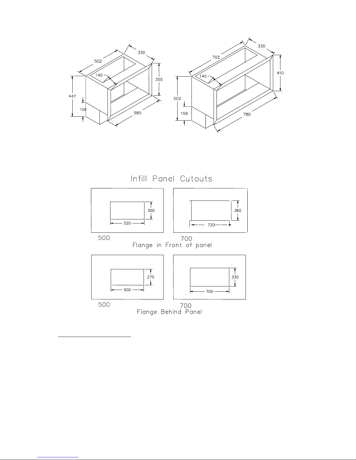
2 The 500 & 700 Fireboxes can be fitted into fireplaces which are large enough or can be
altered to accept these boxes. Their dimensions are shown in Figure 1. If the fireplace
has to be altered a lintel may be required to support the masonry over the opening.
3 Decorative Infill Panels
These appliances can be installed either with a decorative infill panel or directly against
a wall finished with a non combustible material. If an infill panel is to be used the
firebox flange can either be on the outside of the panel and finished with a decorative
trim or the flange can be set on the inside of the infill panel where a trim will not be
required. The size of the hole in the infill panel will vary depending on whether the
flange is inside or outside. The hole sizes required are shown in Figure 2. A trim will be
required if the appliance is to be installed directly against a wall. The depth of the
fireplace opening must be checked against the firebox dimensions given in Figure 1 to
make sure there is space available.
FIGURE 1
FIGURE 2
500
700
Page 4

4
4 The Hearth (Appliances in floor level fireplaces)
Where the appliance is fitted in a floor level builders opening, floor level fireplace recess
or floor level flue box, the hearth shall:
a) Extend through the whole base of the builders opening, fireplace recess or
beneath the flue box.
b) Project at least 300mm in front of any naked flame or incandescent part of
the fire bed.
c) Project at least 150mm beyond each side of any naked flame or incandescent
part of the fire bed, or if there is a non-combustible wall within 150mm of any
naked flame or incandescent part of the fire bed, up to that wall.
d) Have a thickness of not less than 12mm and a minimum height of 50mm
along its front and side edges.
Hole-in-the-wall installations
Where the appliance is installed in a hole-in-the-wall fireplace, a hearth as previously
detailed for floor level fireplaces shall be fitted on the floor beneath the hole so as to
protect combustible material from radiant heat.
a) If a hearth is not to be used, so as to maintain a minimal and contemporary
styling, the appliance must be installed so that every part of any naked flame
or incandescent part of the fire bed is at least 225mm vertically above any
carpet or floor covering.
b) Where no hearth is to be fitted consideration should be given to fixing a
tactile separator to protect young children, the elderly and the infirm. A
tactile separator can be in the form of a fender, kerb, hearth, shelf or
horizontal bar all made from non combustible material and fixed not less
than 50mm & not more than 1000mm above the floor level. They should be
positioned not less than 300mm in front of and 150mm beyond the edge of
any naked flame or incandescent part of the fire bed.
5 The Chimney Flue
Both Appliances The chimney should be of the open-flue type and have a minimum
cross sectional dimension of not less than 175mm.
The flue must have a minimum effective height of 3 metres.
No restrictor plate or flue damper is permitted. Where a variable damper is fitted, this
must be removed.
The chimney must be swept before the appliance is fitted.
500 Model This model may also be connected to 125mm diameter flue liner or twin wall
gas flue using the optional gather and the 125mm adaptor.
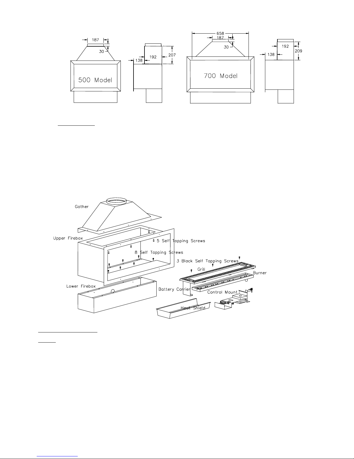
6 Optional Gather
An optional gather is available for both appliances to connect to a flue liner or a twin
wall metal chimney. The dimensions of the gathers are given in Figure 3. Check the
thickness of any masonry plus the decorative infill panel, if used, against the distance
shown between the rear of the flange and the front of the gather. The gather should be
installed before the firebox is finally placed in position and temporarily lodged in
position. After the firebox is properly positioned the gather can be drawn down to the
firebox by gripping the handles provided inside the gather and secured with five self
tapping screws which pass through the top of the firebox into the gather. Please note
that the gather and firebox are not structural items and the flue connected should be
supported and not rest entirely on the gather.
FIGURE 3
Page 5
5
7 Ventilation.
500 Model
Subject to a satisfactory spillage test, there is no requirement for purpose made
ventilation with these models.
700 Model
The room containing the appliance must have a permanent air vent with an effective
open area of at least 100 cm2. The vent must be either direct to outside air or to an
adjacent room having a permanent vent of the same area.
Fitting the Firebox
NOTE
As LPG (Propane Gas) is heavier than air any large voids below an LPG appliance must be back filled
with a suitable material or low level venting must be installed. If low level venting is installed this must
not be connected to the main flueway as this will cause dilution and may well result in lack of flue pull
through the appliance.
1 Check that the fireplace is of the correct size or has been modified to accept the
selected firebox. (See Figure 1).
2 It is recommended that, before proceeding further, a simple smoke test be performed to
check the condition of the chimney. Light a smoke match or a twist of rolled paper,
hold it within the fireplace opening and observe the behaviour of the smoke. If it is
being drawn into the chimney proceed with the installation. If not, pre-heat the
FIGURE 4
Page 6

6
chimney over the period of a few minutes and recheck. If there is any doubt about the
soundness of the chimney a smoke pellet should be used after preheating the flue and
if smoke still fails to clear, further investigation of the chimney is required and the
appliance MUST NOT be fitted until any fault has been rectified.
3 Clear the recess of any loose material. Ensure that the base on which the lower firebox
will stand is level and that the base of the recess and the hearth are horizontal and
non-combustible. If the fire opening is to be elevated the base under the firebox will
have to be raised to suit and the gather built into the fire opening may have to be reformed at a higher level.
4 The gas supply should be routed from the meter or cylinder to a point convenient to the
fireplace.
5 The firebox is made in two sections, the lower part which houses the gas control and
the upper part which is the actual firebox and provides containment of the flame and
products of combustion. See Figure 4.
6 Before starting to install the firebox remove all assembled items from the lower firebox.
The heat shield is retained during transit by self-taper screws these need not be
replaced. Temporarily secure the lower firebox to the upper firebox with four plain selftapping screws. Grommetted gas entry holes are set into the rear and bottom of the
lower firebox.
7 Slide the firebox into the opening. If a decorative infill panel is going to be used and is
not yet in place make sure that the firebox flange clears the front face of the fire
opening by the thickness of the infill panel. Ensure that the flue opening is
unobstructed and gives a clear passage for the products of combustion to the flue. The
firebox may, if required, be fixed in position by making holes in appropriate positions;
the firebox should then be secured with screws and wall plugs to the hearth and/or
rear wall of the fire opening. Do not fully tighten these screws at this time.
8 At this point the installation may be easier if the top part of the firebox is removed from
the bottom to give better access to install the gas supply.
9 Temporarily place the control mount in the lower part of the firebox and run the gas
supply through one of the grommeted holes at the rear or bottom of the lower firebox
and connect it to the gas inlet fitting. IMPORTANT; Ensure both grommets are fitted
correctly in the gas input holes, failure to seal the lower box can allow hot
product to be drawn down past sensitive electronics causing serious damage. This
fitting accepts 8mm diameter tubing. Prior to connecting the gas supply to the
appliance it is important to blow out the supply pipe to clear any of the debris that may
be present and which could cause a blockage in the control valve or pilot. Provision will
have to be made to pass the pipe through the masonry of the fireplace. Care must be
taken to sleeve the supply pipe when passing through the masonry. Exposed pipe
within the fire opening should be wrapped, painted with bituminous paint or factory
sheathed. Disconnect the gas supply and remove the control mount.
10 The space in front of the lower part of the firebox can be filled with masonry and made
good or an infill panel fitted. Slide the upper part of the firebox into position and fix to
the lower part with eight plain self tapping screws. Apply the sealing tape to the inside
of the upper firebox flange, or seal the firebox to the wall or infill panel with a waterbased mastic. Before tightening the fixing screws to the hearth and/or the rear of the
fireplace, the whole box should be pushed firmly back to make a good seal to the wall
or infill panel. THE AREA WITHIN THE FIREPLACE AROUND THE BACK AND SIDES
OF THE FIREBOX SHOULD BE BACKFILLED WITH MINERAL INSULATION MATERIAL
UP TO THE LEVEL OF THE TOP OF THE FIREBOX. This need not be done if the
appliance is sealed into the flue via the optional gather.
11 Inspect the High Tension lead on the control mount, this may have moved during
handling, ensure that it has not come into contact with the sensor or switch leads.
Replace the control mount in position making sure that the holes locate over the studs
Page 7

7
in the base of the firebox. Re-connect the gas supply. Inset four AA batteries into the
battery holder and return it and its carrier to its position at the end of the burner.
(Note; the tab at the front of the battery carrier top should be inserted into its slot and
the whole carrier drawn forward to allow it to seat correctly). Ensure the power lead
from the battery pack is plugged into the power socket at the end of the electronic
control box making sure that any excess wire cannot come into contact with any hot
surfaces. Place the burner heat shield in position. Place the burner in position
ensuring that the mixing tube locates in its hole in the burner mount over the injector.
Carefully place the infill grille in position with the locating tabs engaging with the slots
in the front lower part of the firebox and fix in place at the back of the box with the
three black self tapping screws provided. Since the infill grille locates and secures the
main burner, the burner position may have to be adjusted slightly before the grille will
lay flat. If a decorative outer trim is to be used it can be fixed into position on the frame
of the firebox using the four magnets provided or as directed with the fixing instruction
supplied with the trim.
12 Gas Soundness Check
Once the gas supply is connected, all joints must be checked for gas soundness. Note:
It is permissible to light the fire FOR SHORT PERIODS ONLY when the burner has not
been filled with the loose infill. It is easier to perform these checks if the burner is
placed in position without re-placing the grille as the tube from the manometer can
pass in front of the burner. Please note that the flames from the burner ports will not
all be of equal length.
FILLING THE BURNER.
Fill the burner tray level to the top with either the glass gravel, black ceramic granules
or limestone pebbles provided.
PLACING OF DECORATIVE REFRACTORY SHAPES.
1 Decorative items made from refractory material may be placed on top of the gravel,
granules or pebbles to increase the decorative effect. These items must not reach more
than 100mm (4 inches) above the gravel, etc. and must not be in more than two layers.
If pebbles or coals are selected no more than 17 may be used on the Atina 500.
2 When a fuel pack is used no part of the pebble, coal or log must touch the access plate
above the battery compartment, this would cause the battery pack to over heat and
damage may occur.
3 If the objects on the fire bed become excessively covered in soot they should be removed
from the fire or placed in another position.
FIREJACKS.
Contents of Firejack Pack
3 Small Spheres
2 Large Spheres
7 Small Jacks
6 Medium Jacks
3 Large Jacks
Placing the Jacks and Spheres.
Arrange the objects as desired on top of the granules. Ensure that they are placed so
that air gaps are left between the pieces to allow air to the flames. The height of the
arrangement must not exceed 100mm above the granules. The area around the pilot
flame must be left clear to allow for cross lighting.
Soot Formation.
Some soot will form on pieces placed in the flames but this is generally harmless unless
an excessive amount is deposited. When the fire is cold the pieces can be removed from
the fire and cleaned with a soft brush.
Page 8

8
NOTE:
Sometimes a ‘popping’ noise is produced by the burner at Maximum. This is caused by
a flame repeatedly lighting and then going out. To correct this, carefully examine the
fire and try to identify the flame responsible for the noise. Turn the fire out and with a
screwdriver or similar move either a ceramic piece or some granules in the area of the
flame a small amount. Turn the fire back on and listen for any noise. This process may
have to be repeated several times to cure the problem. At low fire the noise may reappear. This can be reduced by turning the gas control towards Maximum. This is not
harmful to the fire or at all dangerous.
FITTING THE TRIM (IF ORDERED)
Note: When handling the trim it is important that your hands are clean and are
free of oil / grease. We supply disposable gloves & we recommend that they are
worn to avoid unsightly marks.
Insert two of the screws provided into the top two hole in the firebox frame, these
should be screwed in so that there is a gap between the screw head and firebox frame
of approximately 1.5 - 2.0mm, take the remaining two screws and insert them into the
bottom set of holes in the lower firebox frame, these should have a 1.5 – 2.0mm gap as
above. Using the gloves, lift the frame in front of the fire, looking at the rear of the
frame check that it is the correct way up, this is done by looking at the key hole slots,
the smallest slot part of the key hole should be at the top, now lift into position, this is
done by looking through the aperture of the frame and aligning it with the fire box, it is
important that the frame is offered up so that it is central to the opening but
approximately 25mm higher, push the frame back and then lower it gently so that the
frame locates on the four mounting screws, if the frame does not locate onto the screws
remove the frame and very slightly increase the gap between the screw head and fire
frame, a large gap must be avoided as this will result in the frame being loose on the
fire.
COMMISSIONING
Before attempting to light the appliance the gas supply must be turned on by removing
the cap from the isolator fitting and unscrewing the plug all the way out. (This has to be
done before the burner is placed into position and the infill grille fixed down). Replace
the cap making sure that the tab engages with the slot in the top of the plug. Tighten
the cap securely. Inset four AA batteries into battery case located in the battery carrier
at the left hand end of the main burner. Light the appliance in accordance with the
instructions in the Users Guide.
Check for spillage
1 Before briefing the customer on how to use the appliance, a spillage test must be
carried out. The following procedure must be followed.
2 Close all doors and windows in the room or space containing the appliance. Light the
appliance and turn to the maximum rate as detailed in the lighting section of the users
instructions.
3 Light a smoke match and pass completely along and just inside the inner flange that is
just forward of the opening to the chimney. A visual check should ascertain that all the
smoke generated is drawn into the firebox and up the flue.
4 If there is evidence of spillage, the flue should be heated for a period of 5 to 10 minutes
and the test repeated.
5 If there is still evidence of spillage the appliance should turned be off and the chimney
and ventilation investigated. The appliance must not be left in an operational state until
the faults have been identified and corrected.
Page 9

9
Briefing the User
1 Demonstrate the full operation of the appliance to the customer, referring them
specifically to the glass gravel, black ceramic granules or limestone pebbles, any
decorative ceramic shapes and the removal of soot as described in these instructions.
2 Inform the customer that all cleaning procedures should be carried out only when the
appliance is cold.
3 Leave these instructions with the customer.
4 Advise the importance of having the appliance serviced and the chimney checked for
clearance of combustion products on an annual basis.
Page 10

10
USERS GUIDE
Useful tips & recommendations
Once your fire has been fitted, the following recommendations are made to ensure you
enjoy the best results from your purchase;
1 The installation of this appliance must have been carried out by a qualified installer
and in accordance with the requirements of the Gas Safety (Installation & Use)
Regulations
2 The chimney must be swept before the appliance is installed and checked annually to
ensure continued clearance of combustion products and that there is no excessive
build-up of soot.
3 As with any fire, certain components will become hot in use. Care should be exercised
when approaching the appliance when it is hot. We also recommend that a fireguard,
conforming to BS 6539 or BS 6778, be fitted for the protection of young children, the
elderly or infirm.
4 When new any ceramic components may produce a slight odour, but this will
completely vanish after a few hours of use.
5 Handle any ceramic components gently. They are fragile. A soft brush can be used to
clean them of any excess soot. UNDER NO CIRCUMSTANCES should they be washed.
6 Never throw cigarette ends or other foreign matter onto the fire.
7 Never leave the house unattended, with the fire alight, for long periods.
8 Check periodically that any purpose-made ventilation is free from obstruction.
9 To obtain the best results from your fire we recommend that it be serviced annually.
10 These instructions are provided to assist you to operate the fire correctly and should be
kept in a safe place.
11 This appliance is intended for decorative purposes.
12 This appliance is fitted with a flue blockage device that will shut off the appliance in the
event of abnormal flue conditions. This device is NOT a substitute for an independently
mounted carbon monoxide detector.
Operation of the fire
1 It should be noted that your fire is fitted with a Flame Supervision Device, which cuts
off the gas supply to your fire if, for any reason the pilot light is extinguished. It also
monitors constantly the oxygen in the room. The pilot flame heats the thermocouple
probe and allows gas to flow to the burners. If due to pilot failure, the thermocouple
cools, no gas will flow to the main burner. If the fire is turned off or the flames go out,
wait for AT LEAST 3 MINUTES before attempting to relight the fire.
Page 11

11
Lighting the Appliance
1 Fitting the Battery to the Handset
Before using the appliance remove the access cover in the rear of the handset and
insert a 9 volt PP3 size battery. Connect the battery by pushing the connector on to the
terminals. Make sure the battery is connected correctly. Replace the access cover.
2 Using the Handset
When using the handset make sure that it is pointed at the infrared signal receiver
located just in front of the pilot burner at the right hand end of the main burner (the
small black pad )See Figure 5. Unlike a TV control the fire does not react to a quick
press on the button on the handset control. The buttons must be pressed and held
until the control box under the burner acknowledges the signal by emitting a 'beep'
sound (this can take two or three seconds). When the handset is emitting a signal the
red LED at the top of the control will light.
2 Lighting the Fire
MAKE SURE THE ON / OFF SWITCH LOCATED NEAR THE PILOT BURNER HAS BEEN
TURNED TO THE ON POSITION. (Indicated with the symbol 1 ).
To light the fire press the SMALL BUTTON and the UP BUTTON buttons together on the
handset until the fire control box answers with a 'beep'. The fire will go through its start
- up procedure by lighting first the pilot burner and then the main burner on high fire.
This procedure takes about 30 seconds. During this process the fire will emit a regular
series of ‘beeps’. If the fire does not light or there is no reaction when the two buttons
are pressed, press the OFF button to 're-set' the control and try again.
4 Adjusting the Flame Height
To lower the flame height press and hold the DOWN BUTTON until the flame is at the
desired height. To turn the main burner off and just leave the pilot burner alight
continue to press and hold the down button until the main burner goes out. To re-light
the main burner press and hold the SMALL BUTTON and UP BUTTON together until
the flame is at the desired height.
5 Turning the Fire OFF
To turn the fire off but leave the pilot burner alight press the DOWN BUTTON until the
main burner does out. To turn the fire completely off press the OFF button.
Manual Off Facility
If, whilst the fire is alight, the handset control is lost or its battery becomes discharged
the fire can be turned off by switching the appliance ON/OFF switch (located just
behind the signal receiver which is situated just in front of the pilot burner) to the OFF
FIGURE 5
Page 12

12
position which is indicated by the symbol O. Caution should be exercised as this switch
is situated quite close to the pilot flame. Switch back to the ON position to allow the
appliance to be re-lit when required.
Cleaning the fire
1 Ensure that the fire is cold before undertaking any cleaning. Remember that heat is
retained for some time after the fire is switched off. In normal use your fire requires
only minimal cleaning. Some soot may form on any ceramic pieces placed in the flames
but this is generally harmless unless an excessive amount is deposited.
2 If large pieces of debris are found in the fire, sufficient to alter the appearance or
operation of the appliance, the chimney / flue should be inspected and the appliance
serviced before further use.
3 In any event, the chimney should be checked annually to ensure continued clearance of
the combustion products and that there is no excessive build-up of soot.
SERVICE AND MAINTENANCE
The appliance should be serviced at least once a year by a GAS SAFE registered
engineer, and MUST include changing the oxy-pilot.
1 Any refractory shapes should be taken off the fire and shaken to remove any debris but
should only be cleaned if absolutely necessary. This should be done by gently brushing
with a soft brush in a direction away from the person and any persons nearby. This
operation should be performed outside facing downwind. A vacuum cleaner must not
be used for this purpose.
2 Undo the three screws holding the infill grille in position a lift it out of the firebox. Lift
the main burner out of the firebox. The gas supply should be turned off at the
combination pressure test point and isolator fitting. Disconnect the control mount from
the gas supply and lift it out of the lower firebox.
3 Empty the glass gravel from the burner on to a clean surface and thoroughly clean the
burner ports.
4 The pilot burner fitted is an oxygen depletion pilot burner and is the primary safety
device on the appliance. It must therefore be replaced annually. After changing the pilot
burner operate the spark generator and observe that the spark is satisfactory.
5 Lay the control mount assembly on a flat surface and remove, clean and replace the
main injector.
6 Any soot or debris should be removed from the fireplace and flue. The flue should be
inspected for soundness and a smoke test performed as described in the fitting section
to check the condition of the flue.
7 Replace the control mount in position making sure that the holes locate over the studs
in the base of the firebox. Re-connect the gas supply. Place the burner in position
ensuring that the mixing tube locates in its hole in the burner mount over the injector.
Carefully place the infill grille in position with locating tabs engaging with the slots in
the front lower part of the firebox and fix in place with the three screws removed in
paragraph 2. Refill the burner with the glass gravel. Replace any refractory shapes that
were in place on the burner.
8 AFTER REFITTING THE APPLIANCE CHECK FOR GAS SOUNDNESS AT ALL GAS
JOINTS AND TEST FOR SPILLAGE.
Battery Replacement
9 HANDSET; The handset is powered by one Alkaline 9volt PP3 size battery. If the fire
fails to respond to the handset control check that the red LED on the handset lights
whilst pressing the SMALL BUTTON and the UP BUTTON buttons at the same time. If
the LED does not light, the battery in the handset requires renewing. To change the
battery in the handset, remove the battery cover on the underside of the handset,
Page 13

13
unclip the battery from its connector and put a new one put in its place. Replace the
cover.
10 BURNER: (see figure 4) Wait until the fire is cold before attempting to change these
batteries which are in a carrier at the left hand side of the burner. Grip the separate
piece of grille at the left hand side of the burner by inserting two fingers into the holes
provided, tip forwards and lift the battery carrier out of the firebox. Remove the battery
case from the carrier. Open the case by unscrewing the locking screw and remove the
used batteries. Insert four new Lithium AA batteries observing the correct polarity.
Close the case and replace the screw. Place the battery case in the battery carrier and
replace the whole assembly back into the appliance.
Note; Replacement AA Lithium batteries are available from Verine Ltd. Alkaline batteries
are not recommended for this application.
Spare Parts List
In the event of a part requiring replacement the parts list is as follows
Part Description
Part Number
Electronic Control Box and
Remote hand control
G6R - P4S1A5
GV60 Motorised valve
GV60M1- C5D1H1L
Oxypilot (NG models)
OP9037
Oxypilot (LPG models)
OP9223
Burner Control Battery
Energiser 1.5 volt AA Size Lithium L91
Page 14

14
Installation & Service Record
Please ensure that installer completes the installation record below
INSTALLATION RECORD
Appliance Supplied by: …………………………....
Installation Date: ……………Serial No.: ….……...
Installed By: …………..…...GAS SAFE No.: …..……
Signed by Installer: ………………………..…
RECORD OF 1st SERVICE
Serviced by: ………..…….. GAS SAFE
No.:……………....
Service Date: ……………… Signed: .………….….…...
Comments: ……………………………………..…….……
…………………………………………………………………
…………………………………………………………………
RECORD OF 2nd SERVICE
Serviced by: ………..…….. GAS SAFE
No.:……………....
Service Date: ……………… Signed: .………….….…...
Comments: ……………………………………..…….……
…………………………………………………………………
…………………………………………………………………
RECORD OF 3rd SERVICE
Serviced by: ………..…….. GAS SAFE
No.:……………....
Service Date: ……………… Signed: .………….….…...
Comments: ……………………………………..…….……
…………………………………………………………………
…………………………………………………………………
RECORD OF 4th SERVICE
Serviced by: ………..…….. GAS SAFE
No.:……………....
Service Date: ……………… Signed: .………….….…...
Comments: ……………………………………..…….……
…………………………………………………………………
…………………………………………………………………
RECORD OF 5th SERVICE
Serviced by: ………..…….. GAS SAFE
No.:……………....
Service Date: ……………… Signed: .………….….…...
Comments: ……………………………………..…….……
…………………………………………………………………
…………………………………………………………………
RECORD OF 6th SERVICE
Serviced by: ………..…….. GAS SAFE
No.:……………....
Service Date: ……………… Signed: .………….….…...
Comments: ……………………………………..…….……
…………………………………………………………………
…………………………………………………………………
RECORD OF 7th SERVICE
Serviced by: ………..…….. GAS SAFE
No.:……………....
Service Date: ……………… Signed: .………….….…...
Comments: ……………………………………..…….……
…………………………………………………………………
…………………………………………………………………
RECORD OF 8th SERVICE
Serviced by: ………..…….. GAS SAFE
No.:……………....
Service Date: ……………… Signed: .………….….…...
Comments: ……………………………………..…….……
…………………………………………………………………
…………………………………………………………………
Page 15

15
B-111620
Issue 3
BFM Europe Limited
Trentham Lakes
Stoke on Trent, Staffordshire ST4 4TJ
Tel: (01782) 339000 Fax: (01782) 339009
Email: info@bfm-europe.com
www.bfm-europe.com
THIS BOOKLET CONTAINS 15 PAGES.
ATINA/VERTEX/1007/II/UI
 Loading...