

Verine Alpena NBFC**MN2, Alpena NBFC**EN2, Alpena NBFC**RN2, Alpena NBFC**MP2, Alpena Installation, Maintenance & User Instructions
Page 1

Alpena
COAL EFFECT BALANCED FLUE GAS FIRE
Installation, Maintenance & User Instructions
Hand these instructions to the user
Model No. NBFC**MN2, NBFC**RN2 & NBFC**EN2 are for use on Natural Gas
(G20) at a supply pressure of 20 mbar in G.B. / I.E.
Model No. NBFC**MP2 is for use on Propane Gas (G31) at a supply pressure
of 37 mbar in G.B. / I.E.
** denotes trim / fret or fascia variant
Page 2

CONTENTS
P
AGE
Section 1 Information and Requirements
1
.0 Appliance Information 3
1
.1 Conditions of Installation 4
1.2 Fireplace surround & suitability 4
1.3 Flue Terminal Position 5
1
.4 Shelf position 6
1.5 Hearths 6
Section 2 Installation of Fire
2.1 Unpacking the fire 6
2.2 Fireplace opening 7-8
2.3 Preparation of the wall 8-9
2.4 Preparation of the flue hole 9
2.5 Installation of the gas supply 10
2.6 Preparation of the flue duct 11
2.7 Securing the firebox to the opening 12-13
2.8 Making the gas connection 13
2.9 Fitting the terminal guard 14
2.10 Removal & refitting of the glass frame 15
Section 3 Assembling Fuel Bed and Commissioning
3.1 Fitting the fuel bed 16-18
3.2 Fitting the trim 18
3.3 Fitting the fret 18
3.4 Lighting the appliance (MC variants) 19
3.5 Fixing the infrared sensor in position (RC variants) 20
3.6 Connecting the battery pack (RC variants) 21
3.7 Lighting the appliance (RC variants) 22
3.8 Lighting the appliance (EFC variants) 23
Section 4 Maintenance
4.1 Removal of the burner assembly (all variants) 24
4.2 Removal of the piezo Igniter (MC variants) 24
4.3 Removal of the control valve (MC variants) 25
4.4 Removal of the pilot assembly (all variants) 25
4.5 Removal of the control board (RC & EFC variants) 26
4.6 Removal of the control valve (RC & EFC variants) 26
4.7 Removal of the IR sensor (RC variants) 26
4.8 Removal of the battery holder / lead (RC & EFC variants) 26
4.9 Removal of the EFC trim switch 27
4.10 Parts shortlist 27
Section 5 User Instructions
5.1 Installation Information / about your fire 28-29
5.2 Operating your fire (MC variants) 30
5.3 Operating your fire (RC variants) 31
5.4 Operating your fire (EFC variants) 32
5.5 Turning off the RC / EFC model if the handset is lost or broken 33
5.6 Changing the batteries (RC / EFC variants) 33
5.7 Removal / replacing the glass frame 34
5.8 Removal / replacing the fuel-bed 35-37
5.9 User replaceable parts 38
BFM Europe Ltd, Trentham Lakes, Stoke-on-Trent, Staffordshire, ST4 4TJ
2
Page 3
SECTION 1
INFORMATION AND REQUIREMENTS
1.0 APPLIANCE INFORMATION
Natural Gas LPG
Main injector : (1 off) 1.65mm 1.20mm
Pilot Type - S.I.T.140 Series Size 27 Size 19
Max. Gross Heat Input : 4.6kW 4.8kW
Min. Gross Heat Input : 3.2kW 3.4kW
Gas Rate : 0.427 m3/hr 0.180 m3/hr
Cold Pressure : 20.0+/-1.0 mbar 37.0+/-1.0 mbar
Ignition : Push-button Piezo (MC models only)
Ignition : Electronic (RC & EFC models only)
Electrode Spark Gap : 4.0mm
Weight (without fender) : 25.0 kg inclusive of flue pipe and terminal
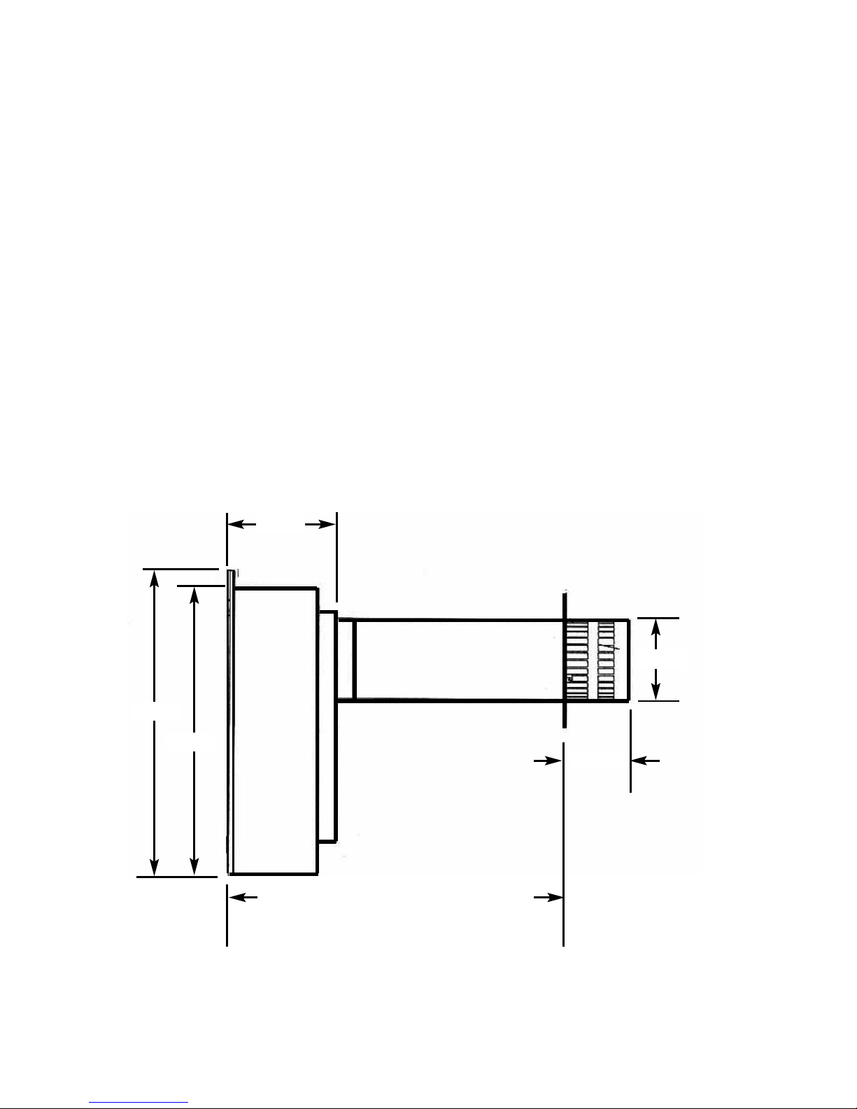
Fig 1
3
185mm
285mm Min, 625mm Max with standard flue
duct on MC / RC models. 248mm Min,
588mm Max with standard flue duct on EFC
models. A cost option extended flue duct (part
no. CV-MARLT) can be purchased to increase
this dimension on NG MC / RC models to
1010mm or 973mm on NG EFC models)
120mm
580mm
550mm
150mm
Page 4

INSTALLATION REQUIREMENTS
Efficiency Declaration
The efficiency of this appliance has been measured as specified in
BS EN 613 : 2001 and the result is 85%. The gross calorific value of the fuel has
been used for this efficiency calculation.
The test data from which it has been calculated has been certified by BSI Testing
Services.
The efficiency value may be used in the UK Government’s Standard Assessment
Procedure (SAP) for energy rating of dwellings.
1.1 CONDITIONS OF INSTALLATION
It is the law that all gas appliances are installed only by a GAS SAFE Registered
Installer, in accordance with these installation instructions and the Gas Safety
(Installation and Use) Regulations 1998 as amended. Failure to install appliances
correctly could lead to prosecution. It is in your own interest and that of safety to
comply with the law.
The installation must also be in accordance with all relevant parts of the Local and
National Building Regulations where appropriate, the Building Regulations
(Scotland Consolidation) issued by the Scottish Development Department, and all
applicable requirements of the following British Standard Code of Practice.
1. B.S. 5871 Part 1 Installation of Gas Fires
2. B.S. 6891 Installation of Gas Pipework
3. B.S. 5440 Parts 1 & 2 Installation of Flues and Ventilation
4. I.S 813 : 1996 Domestic Gas Installation, issued by the National Standards
Authority of Ireland.
1.2 FIREPLACE / SURROUND SUITABILITY
This product is designed to fit fireplaces with a minimum 1” / 25mm rebate. The
fire must only be installed on a hearth it must not be installed directly onto
carpet or other combustible floor materials. The fire is suitable for fitting to
non-combustible fire place surrounds and proprietary fire place surrounds with a
temperature rating of at least 150 degrees celcius (Class “O”).
Soft wall coverings such as blown vinyl, wall paper etc. could be affected by
the rising hot air and scorching and/or discoloration may result. Due consideration should be made to this when installing or decorating.
4
Page 5
1.3 FLUE TERMINAL POSITION
The minimum acceptable dimensions from the flue terminal to obstructions
and ventilation openings are shown below and listed in the table
It is important that the position of the flue allows the free passage of air
across it at all times. The minimum acceptable space from the flue terminal
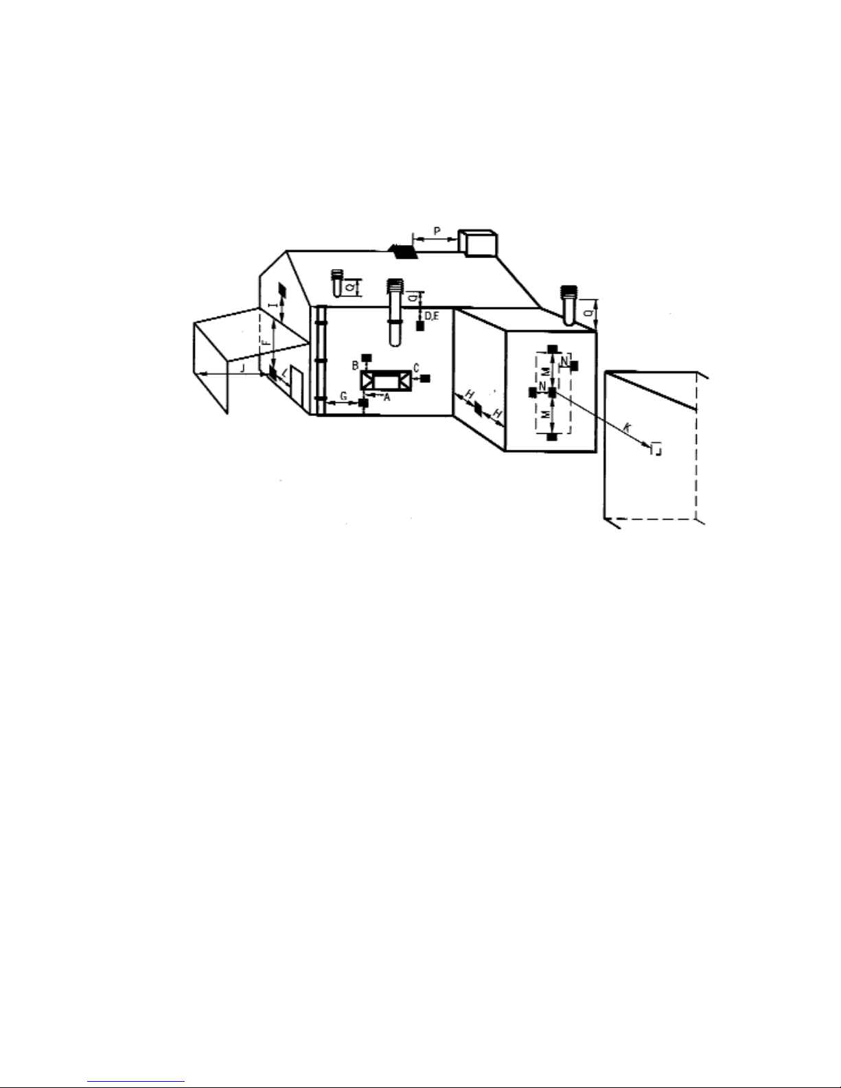
to obstructions and ventilation openings are specified below (Fig. 2)
Fig. 2
DIMENSION TERMINAL POSITION MINIMUM DIMENSION
A Directly below an opening, air brick, 300mm (12in)
opening window
B Above an opening, air brick, 300mm (12in)
opening window
C Horizontally to an opening, air brick,
opening window etc.
D Below gutters, soil pipes or drain pipes 300mm (12in)
E Below eaves 300mm (12in)
F Below balconies or car port roof 600mm (12in)
G From a vertical drain pipe or soil pipe 300mm (12in)
H From an internal or external corner 600mm (24in)
I Above ground roof or balcony level 300mm (12in)
J From a surface facing the terminal 600mm (24in)
K From a terminal facing the terminal 600mm (24in)
L From an opening in the car port 1200m (48in)
M Vertically from a terminal on the same wall 1500mm(59in)
N Horizontally from a terminal on the 300mm (12in)
same Wall
O NOT APPLICABLE N/A
P NOT APPLICABLE N/A
Q NOT APPLICABLE N/A
5
Page 6

1.4 SHELF POSITION
The fire may be fitted below a combustible shelf providing there is a minimum
distance of 200mm above the top of the fire and the shelf does not project more
than 150mm. If the shelf overhangs more than 150mm the distance between the
fire and the shelf must be increased by 15mm for every 25mm of additional
overhang over 150mm.
1.5 HEARTHS
This appliance must only be installed on to a concrete or non-combustible hearth.
The hearth material must be a minimum thickness of 12mm with the top surface at
least 50mm above the floor. The hearth must be fitted symmetrically about the fire
opening and have a minimum width of 760mm and a minimum projection of
300mm forwards from the fire opening.
SECTION 2
INSTALLATION OF FIRE
2.1 UNPACKING THE FIRE
Carefully lift the fire out of the carton. Remove the loose item packaging carefully
from the the pack. Check the contents as listed :-
IMPORTANT
: THE CARDBOARD FITMENT THAT IS AT THE TOP OF THE
CONVECTION APERTURE SHOULD NOT BE REMOVED
UNTIL THE APPLIANCE IS FULLY INSTALLED AND READY
TO BE LIT.
DO NOT UNDER ANY CIRCUMSTANCES USE THIS APPLIANCE IF THE
GLASS PANEL IS BROKEN OR NOT SECURELY FIXED TO THE FIREBOX.
Packing Check List
1 off Fire box & foam seal / burner assembly
1 off Boxed ceramic 5 piece fuel bed set
1 off Flue terminal / pipe unit
1 off Flue terminal guard
1 off Loose Items pack including cable fixing kit
1 off Installation / user manual (combined)
6 off AA batteries (RC / EFC models only)
1 off PP3 battery (RC models only)
1 off Rubber grommet (to seal gas aperture used)
6
Page 7
2.2 FIRE PLACE OPENING
2.2.1 The front opening of the fire place must be between 410 and 420mm
wide, and between 555 and 570mm high. If the opening exceeds these
dimensions then a surround must be constructed from suitable noncombustible material to produce a suitable sized opening. Any surround
must be suitably sealed to the fire place to prevent leakage.
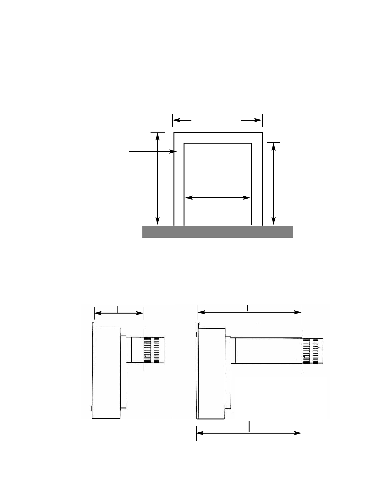
See fig. 3 below
Fig. 3
2.2.2 The minimum / maximum sized distances between the firebox mounting
flange and outside wall are shown below in Fig. 4
Fig. 4
7
590mm minimum
4
90mm minimum
Fire Opening
410mm minimum
420mm maximum
555mm
minimum,
570mm
maximum
Minimum Flat
Sealing Area
Minimum Installation Depth
285mm MC / RC models
Minimum Installation Depth
248mm EFC models
Maximum Installation Depth 625mm
with standard flue duct MC / RC models
Maximum Installation Depth 588mm
with standard flue duct EFC models
Maximum Installation Depth
1010mm with extended flue duct
on MC / RC models
973mm on EFC models (cost
option extra) - suitable for NG
models only on all control options
Page 8
2.2.3 NOTE : WHEN MEASURING LENGTH BETWEEN FIREBOX AND
THE OUTER WALL TAKE INTO ACCOUNT THE DISTANCE
BETWEEN THE BACK OF THE FIREBOX AND THE INNER WALL AS
THIS WILL VARY BETWEEN INSTALLATIONS, DEPENDENT UPON
THE FIRE SURROUND REBATE OR CAVITY DEPTH. (DIMENSION
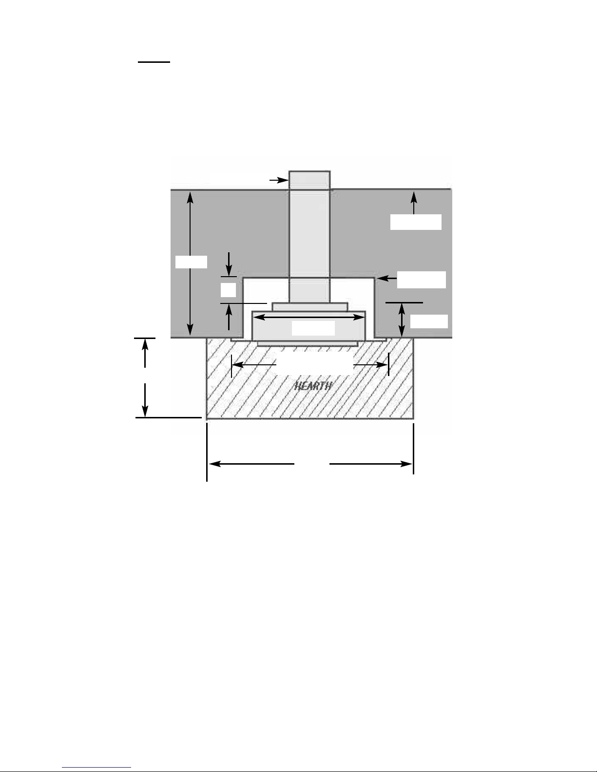
“X” BELOW - FIG. 5).
Fig. 5
2.2.4 The appliance must be fitted into a fireplace or false chimney
constructed of non-combustible materials, minimum width 410mm,
minimum height 555mm and minimum surround or false chimney breast
rebate 75mm.
2.3 PREPARATION OF THE WALL
2.3.1 The appliance and flue pipes must be installed at right angles to the
mounting wall. The appliance itself should be installed vertically against
a flat wall. Where an uneven wall surface is found, appropriate action
should be taken to ensure that the appliance is not stressed or does not
distort when installed.
Ensure that the floor surface onto which the appliance is mounted onto
is flat. The minimum height from the floor to the centre of the flue is
shown on fig. 6 overpage.
760mm
405mm
185mm
X
Outer Wall
Inner Wall
485mm Including
Firebox Flanges
8
300mm
Cavity
F
lue Terminal
Page 9
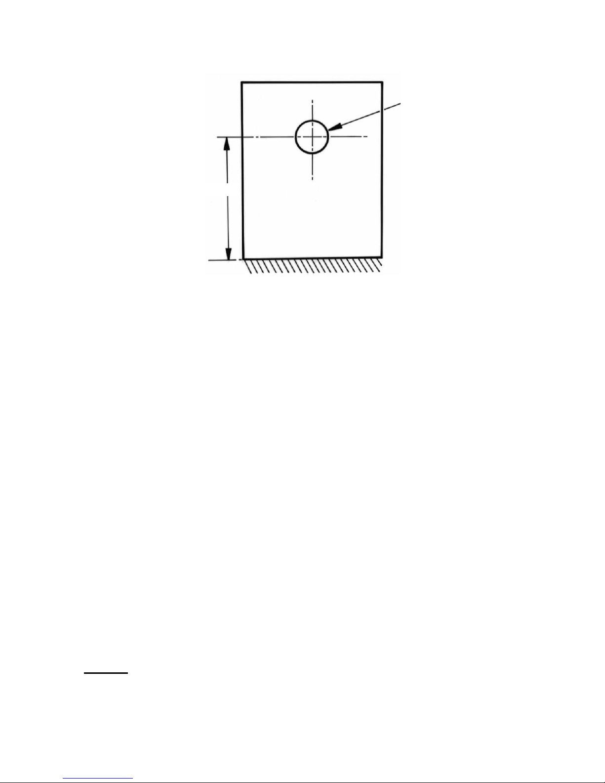
Fig. 6
2.4 PREPARATION OF THE FLUE HOLE
2.4.1 Mark the position of the centre of the flue on the inner wall.
2.4.2 Cut hole for outer flue pipe. There are two possible methods to achieve
this, either core drill or via hammer and chisel.
2.4.3 To core drill, proceed as follows :-
Drill a pilot hole through the wall, in position as specified in figure 6.
Using a 6” core drill, drill the flue hole.
To Hammer and chisel, proceed as follows :-
Mark the position of the centre of the flue pipe as specified in figure 6.
Mark the position of the hole around this point.
Chisel out the area as marked on the wall.
2.4.4 We then recommend that a cardboard cylinder is placed around the flue
pipe and inserted in the chiselled out hole whilst making good.
NOTE :-
If the appliance is to be installed into a building under
construction, it is recommended that a non-corrosive metal
tube of 6” diameter be inserted into the position of the hole.
150mm diameter
4
23mm
9
Page 10
2.5 INSTALLATION OF THE GAS SUPPLY
2.5.1 Before installing the firebox, decide from which side or if a rear
connection to the gas supply is required. Plan the pipe run to enter the
firebox from the left, right or rear and connect to the inlet elbow. See
below :-
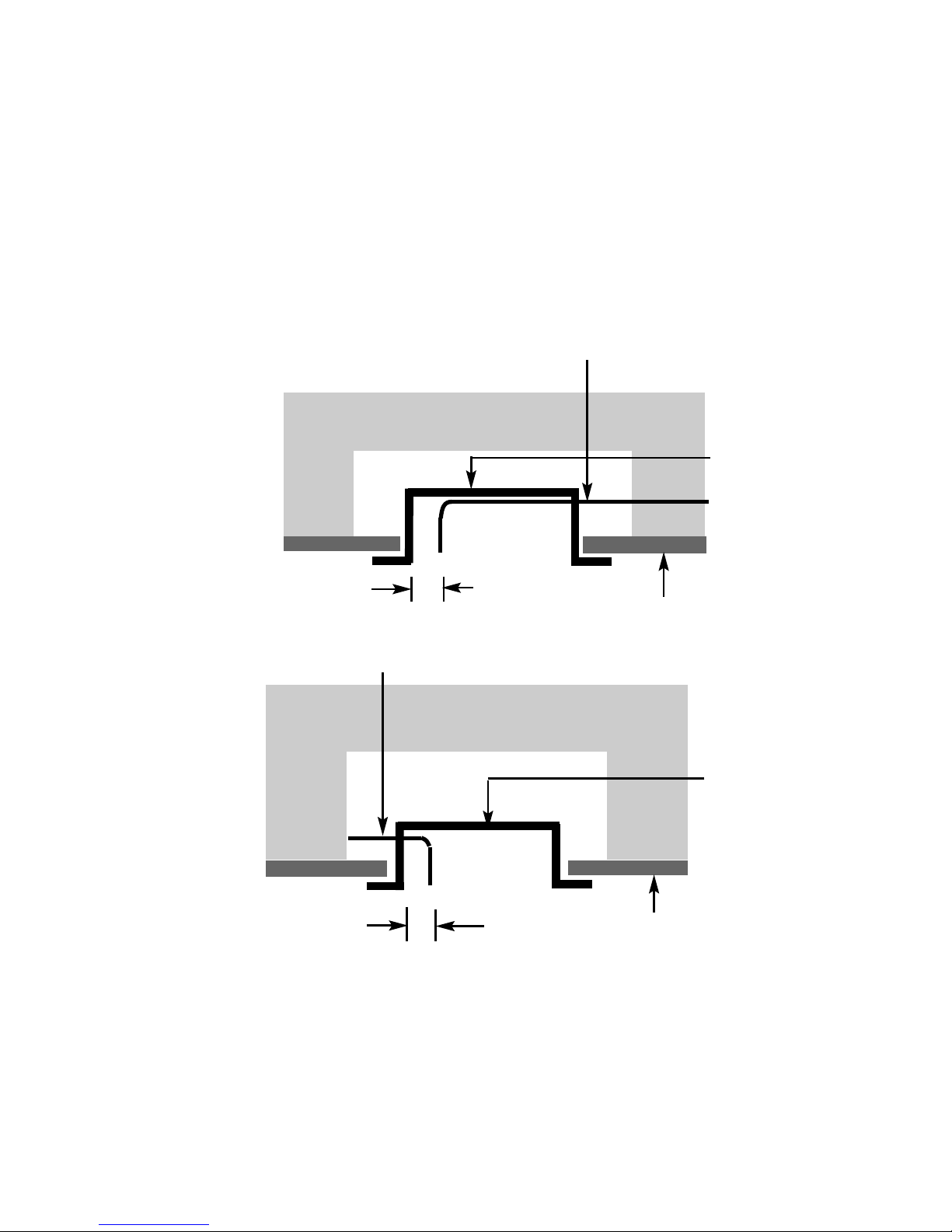
2.5.2 If concealed pipe work is required plan the pipe run to enter the fire box
through one of the openings in the sides or rear of the fire box and
connect to the inlet elbow. See Fig. 7 & 8 below for a suggested
concealed pipe layout.
Fig. 7
Fig. 8
Note : Before breaking into the gas supply a pressure drop test should be
carried out to establish that the existing pipework is sound. Always insert
the grommet into the entry point used (a sharp blow with a hammer or chisel
will be sufficient to knock out the opening selected in the firebox) and with
the grommet fitted cut with a sharp knife to allow the supply pipework to
pass through into the firebox.
10
Firebox
Fireplace
Gas Supply
Firebox
Approx.
40mm
Fireplace
Gas Supply
Approx.
40mm
Page 11
2.6 PREPARATION OF THE FLUE DUCT
2.6.1 Place the firebox into the fire opening with fire surround correctly
secured in the final position. From the outside of the house measure
from the face of the outside wall to the rear panel of the firebox through
the flue hole. Cut the flue duct to this size, using the polythene support
ring to support the flue whilst being cut. Remove the polystyrene
support ring from the flue duct and remove burrs from the pipe.
IMPORTANT : ENSURE THE PIPES ARE CUT SQUARELY.
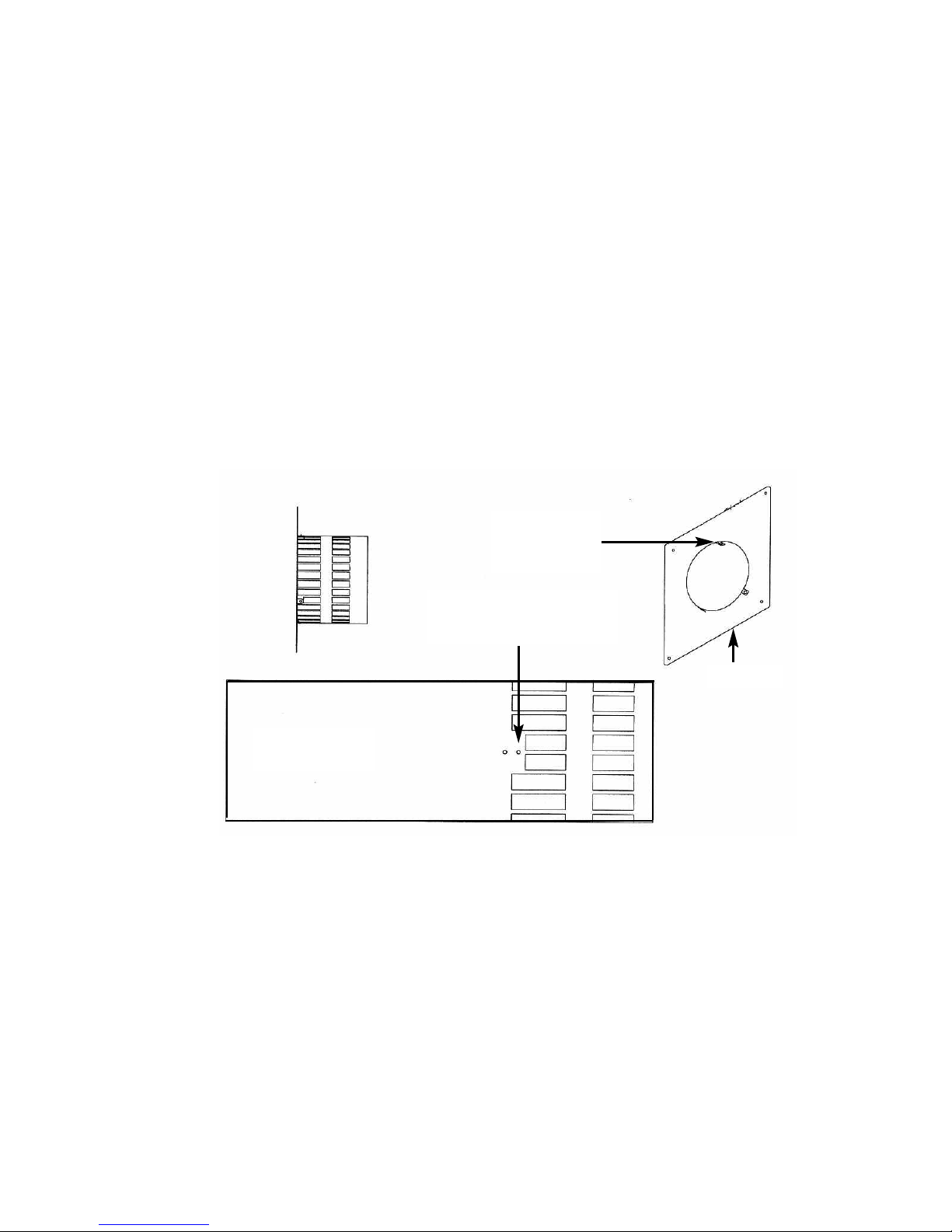
2.6.2 The joint between the firebox and the flue duct as shown below in Fig. 9
must be secured with screws and sealed with the foil tape as supplied.
In order to do this, the wall plate must removed from the flue pipe /
termination.
Fig. 9
2.6.3 Due to the varying lengths of flue that will be required via differing
installations it will be necessary to drill the flue pipe using the 3 off holes
in the mounting flange on the rear of the combustion chamber as a
guide for positioning. When the holes have been drilled and the screws
fitted, wrap the joint with the foil tape supplied.
2.6.4 Re-fit the wall plate ensuring the outer set of holes as indicated above
in Fig. 9 are used. Use a high temperature sealant to secure the wall
plate to the outside wall of the property before securing with the screws
and rawlplugs supplied to ensure a mechanical fix.
11
Lug as shown
should be fitted
uppermost
Wall Plate
Flue
Termination / Pipe
Use the outer set of holes to
secure the wall plate to the
flue pipe / termination
Page 12
2.7 SECURING OF FIREBOX TO THE OPENING
2.7.1 There is a choice of methods of fixing the firebox that are provided to
enable the installer to deal with any type of installation. The preferred
method of fixing the appliance is the cable fixing method, which is
described in detail in the following section.
2.7.2 If the standard firebox fixing flange is to be used, the firebox may be
secured using the cable method, but in installations where the cable
method is not suitable, e.g.insufficient space behind the firebox, or
loose masonry, the firebox can be fitted directly to either the front of the
fireplace via the flange with the four off screws provided. The firebox will
require sealing to the fireplace, regardless of the method used.
2.7.3 To secure the fire using the preferred cable method, proceed as follows
below :-
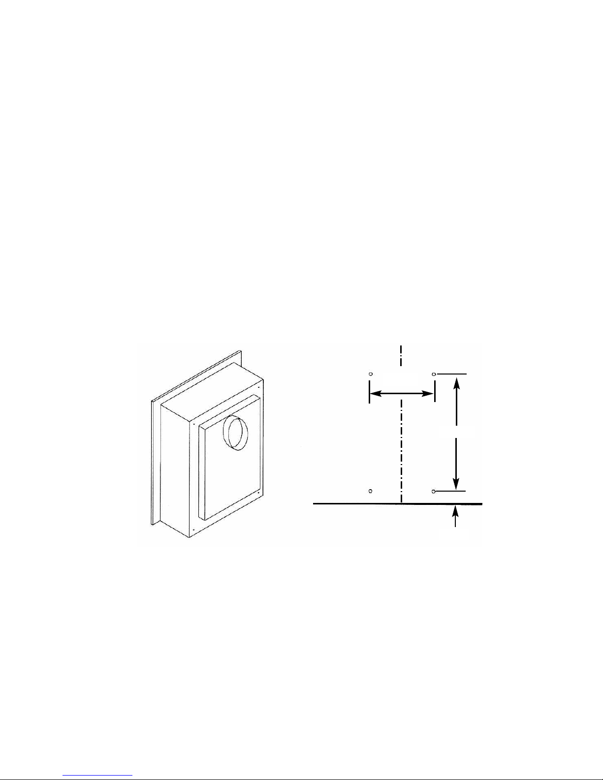
2.7.4 Mark out and drill 4 off No 14 6mm holes in the rear face of the fire
opening in the positions as shown in Fig. 10 below.
Fig. 10
2.7.5 Fit the wall plugs provided and screw the fixing eyes securely into the
rear of the fire opening.
2.7.6 Uncoil the two fire fixing cables and thread one end of the each of the
cables through the rear of the fire box, and through each fixing eye at
the top. Thread both cables through the fixing eye’s at the bottom, then
the holes at the bottom of the firebox
2.7.7 Thread the cables through the rear of the firebox, insert the flue pipe /
terminal through the hole in the rear of the opening and offer the firebox
up to the fireplace.
12
360mm
500mm
50mm
Page 13

2.7.8 To improve access to tension the screws it may be advantageous to
remove the control panel from the fire. To do this, remove the 4 off
retaining screws and on MC models, remove the control valve retaining
nut.
2.7.9 Thread a tensioning screw over both of the cables and ensure that the
tensioning nut is screwed fully up against the hexagon shoulder of the
tensioning screw (this provides maximum travel for the tensioning nut).
2.7.10 Fit a screwed nipple on to each of the cables and pull hand tight up
against the tensioning screw, then secure each nipple with a flat bladed
screwdriver.
2.7.11 Before making the final gas connection, thoroughly purge the gas
supply pipework to remove all foreign matter, otherwise serious
damage may be caused to the gas control valve on the fire.
Failure to purge the gas supply will invalidate the guarantee.
2.8 MAKING THE GAS CONNECTION / PRESSURE TESTING
2.8.1 The gas connection should be made to the appliance inlet elbow to
using 8mm rigid tubing.
2.8.2 Remove the pressure test point screw from the inlet elbow and fit a
manometer.
2.8.3 Turn on the main gas supply and carry out a gas tightness test.
2.8.4 Depress the control knob and turn anti-clockwise to the position marked
pilot. Hold in the control knob for a few seconds to purge the pipe work
then press the igniter button. The burner should light, continue to hold
the control knob for a few seconds then turn to the full-on position. If
lighting an RC or EFC variant , please consult section 3.5 to 3.8.
2.8.5 Check that the gas pressure is 20.0 mbar (+/- 1.0mbar) 8.0 in w.g.(+/-
0.4 in w.g.) for NG models and 37.0 mbar (+/- 1.0mbar) 14.8 in
w.g.(+/- 0.4 in w.g.) for LPG models
2.8.6 Turn off the fire, remove the manometer and refit the pressure test point
screw. Check the pressure test point screw for gas tightness with the
appliance turned on using a suitable leak detection fluid or detector.
13
Page 14

2.9 FITTING THE TERMINAL GUARD
2.9.1 With the flue terminal in position, place the terminal guard over the top
of the flue terminal and mark the position of the holes on the outer wall.
2.9.2 Remove the terminal guard and drill the 4 off 6 mm holes.
2.9.3 Insert the raw plugs into the drilled holes, replace the terminal guard
over the top of the flue terminal and attach to the wall using the No.12 x
40mm screws provided with the terminal guard.
NOTE :
In England & Wales, building regulations require that a terminal
guard should be fitted if the terminal could come into contact with people
near the building or be subject to damage. BFM Europe Ltd. also
recommend the fitting of a flue terminal guard where regulations do not
demand that it be fitted. A suitable flue terminal guard is supplied with the
appliance.
14
Page 15

2.10 REMOVING & REFITTING OF THE GLASS FRAME.
2.10.1 Remove the 2 screws which hold the convection slot cover to the
firebox, as shown below in Fig 11
2.10.2 Remove the burner heat shield by unscrewing the 2 off retaining screws
as shown below in Fig. 11
2.10.3 Remove the 4 off M5 retaining nuts as shown below in Fig. 11
2.10.4 Remove the 3 off top retaining screws as shown below in Fig. 11
2.10.5 Remove the 2 off bottom retaining screws as shown below in Fig. 11
2.10.6 Re-assemble in reverse order.
NOTE :
Always ensure that a consistent seal between the combustion
chamber and the glass frame is achieved.
Fig. 11
15
Burner heat
shield, secured by
2 screws
Glass frame assembly,
secured by 5 off
screws and 4 off M5
retaining nuts
Convection slot
cover, secured by 2
screws
Page 16

SECTION 3
ASSEMBLING FUEL BED AND COMMISSIONING
3.1 FITTING THE FUELBED
3.1.1 Place the ceramic fibre support behind the burner as shown below in
Fig. 12
Fig. 12
3.1.2 Place the front right coal moulding onto the front coal support as shown
below in Fig. 13
Fig. 13
16
Right Front Coal Moulding
Front Coal Support
Page 17

3.1.3 Place the front left coal moulding onto the front coal support as shown
below in Fig. 14
Fig. 14
3.1.4 Place the upper right coal moulding as shown below in Fig. 15. This
moulding tucks under the front right coal moulding and is supported by
the ceramic fibre support.
Fig. 15
17
Left Front Coal Moulding
Upper Right Coal Moulding
Page 18

3.1.5 Place the upper left coal moulding as shown below in Fig. 16. This
moulding tucks under the front left coal moulding and is supported by
the ceramic fibre support.
Fig. 16
3.1.5 Refit the glass frame as detailed in section 2.10, then light the
appliance as detailed in section 3.2 / 3.3
To ensure that the release of fibres from these R.C.F (Refractory Ceramic
Fibre) articles is kept to a minimum, during installation and servicing we
recommend that you use a HEPA filtered vacuum to remove any dust
accumulated in and around the appliance before and after working on the
appliance. When replacing these articles we recommend that the replaced
items are not broken up, but are sealed within heavy duty polythene bags,
clearly labelled as “RCF waste”. RCF waste is classed as a “stable”, non
reactive hazardous waste and may be disposed of at a landfill licensed to
accept such waste Protective clothing is not required when handling these
articles, but we recommend you follow the normal hygiene rules of not
smoking, eating or drinking in the work area, and always wash your hands
before eating or drinking.
3.2 FITTING THE TRIM (ALL MODELS)
3.2.1 The trim is held in position on the fixing flange by magnets.
3.3 FITTING THE FENDER (ALL MODELS)
3.3.1 The fender is placed up to the front of the ceramic front rail on
all models. Position the ashpan under the fender and centralise.
18
Upper Left Coal Moulding
Page 19

3.4 LIGHTING THE APPLIANCE - MANUAL CONTROL VARIANTS
IMPORTANT NOTE : IF THE BURNER IS EXTINGUISHED FOR ANY
REASON YOU MUST ENSURE THAT YOU WAIT A FULL FIVE
MINUTES BEFORE ATTEMPTING TO RE-LIGHT THE FIRE.
WHEN TURNING THE FIRE “OFF” PLEASE ENSURE THAT THE
CONTROL VALVE IS TURNED TO THE “OFF” POSITION AND THE
PILOT FLAME IS EXTINGUISHED. DO NOT LEAVE THE PILOT
FLAME ONLY LIT.
3.4.1 Turn on the gas restrictor at the inlet fitting.
3.4.2 Depress the control knob and turn anti-clockwise to the position marked
pilot. Hold in the control knob for a few seconds to purge the pipe work.
3.4.3 Continue to hold-in the control knob and press the igniter button. If the
burner does not light, continue to press the igniter button until ignition
occurs. Continue to hold the control knob for 5-10 seconds to allow
thermocouple to heat up, if the pilot goes out when the control knob is
released, repeat the lighting sequence.
3.4.4 Turn the control knob in the anti-clockwise direction to the high position
and the main burner will light.
3.4.5 Turn the control knob clockwise to the low position and the gas input
will be reduced to the minimum setting.
3.4.6 Slightly depress the control knob and turn to the pilot position, the main
burner will go out but the pilot will remain lit.
3.4.7 Slightly depress the control knob and turn to the off position, the pilot
will now be extinguished.
3.4.8 After ensuring that the fire is safe to use it should be left on high
position to fully warm up. During this time a slight odour may be
noticed, this is due to the “newness” of the fire and will soon disappear.
Finally, hand the Installation and Maintenance Instructions and the Users
Instructions over to the customer and explain the operation of the fire.
NOTE : THIS APPLIANCE IS DESIGNED TO WORK SAFELY AND
EFFECTIVELY DURING ADVERSE WEATHER CONDITIONS.
HOWEVER, DURING SUCH TIMES FLAME DISTURBANCE
MAY BE NOTICED. THIS IS NORMAL AND DOES NOT
EFFECT OR IMPAIR THE SAFETY OF THE APPLIANCE.
19
Page 20

3.5 FIXING THE INFRARED SENSOR IN POSITION - REMOTE
CONTROL MODELS ONLY
3.5.1 Due to the different fascia’s that can be supplied with these fires, the
infrared sensor is supplied from the factory attached to a self adhesive
pad. This pad can therefore be attached to the hearth in a position to
suit the form of the fret assembly that is chosen with the product.
Fig. 17 below shows the self adhesive pad and infrared eye attached
to the flying lead, as supplied from the factory.
Fig. 17
3.5.2 Remove the backing paper from the self adhesive pad and position the
infrared eye in the air channels in the ashpan cover, so that the infrared
eye is flush with the front edge of the ashpan cover, as shown below in
Fig. 18. Check the operation of the fire / handset, as detailed in Section
3.7 and adjust the position of the infrared eye if necessary.
Fig. 18
20
Infrared Eye
Flying Lead
Infrared Eye Sensor
Self Adhesive Pad
Correct final position
of the Infrared Eye
Sensor
Page 21

3.6 CONNECTING THE BATTERY PACK - REMOTE CONTROL &
ELECTRONIC FIRE CONTROL MODELS ONLY.
3.6.1 To prevent un-necessary battery drain, the battery pack that is
used to provide the remote and electronic control function for this
product is disconnected at the factory. Prior to attempting to light the
product, can the installer please ensure that the battery pack is re-con
nected as shown in section 3.6.2 & 3.6.3 below.
3.6.2 Locate the battery pack in the support cradle at the bottom R/H side of
the firebox / burner assembly.
3.6.3 The wire and connecting plug from the battery pack should then be
connected into the supply wire running from the control board. See Fig
19 below.
Fig. 19
3.6.4 Replace the battery pack into its mounting cradle below the burner.
3.6.5 On RC models, fit the PP3 battery to the remote handset by removing
the rear cover and connecting the battery to the connecting plug.
Replace the cover on the handset.
21
Battery
Pack
Connecting Wire
Connecting
Plug
Page 22

3.7 LIGHTING THE APPLIANCE - REMOTE CONTROL MODELS ONLY
3.7.1 The Remote control handset generates an infrared signal, which will be
received by the sensor situated at the front right of your fire, behind the
ashpan cover. This infrared signal requires direct line of sight from the
handset to the sensor on the fire to ensure good operation.
3.7.2 To light the appliance using the handset, point the handset at the fire
and press the 2 left hand buttons together as shown below in Fig. 20
The fire will emit a “beep” sound, the buttons can now be released. After
a few seconds an audible clicking can be heard and then the fire will
light the pilot and then light the main burner. The ignition cycle will take
approximately 20 seconds.
3.7.3 To reduce the level of heat input on the fire, point the handset at the fire
and press the small flame button. (An audible beep will be heard)
3.7.4 To increase the level of heat input on the fire, point the handset at the
fire and press the large flame button. (An audible beep will be heard)
3.7.5 To leave the fire in the standby mode (pilot only running) press the small
round button on the handset.
3.7.6 To switch the appliance off completely, press the large round button on
the handset, the fire will then switch off.
Fig. 20
WHEN TURNING THE FIRE “OFF” PLEASE ENSURE THAT THE PILOT
FLAME IS EXTINGUISHED. DO NOT LEAVE THE PILOT FLAME ONLY LIT.
22
Off Button
High (Large Flame)
Low (Small Flame)
Standby Button
Page 23

3.8 LIGHTING THE APPLIANCE - ELECTRONIC FIRE CONTROL
MODELS ONLY
3.8.1 To light the fire using the electronic fire control, press the ignition button
as indicated below in Fig. 21. The fire will emit a “beep” sound, the
buttons can now be released. After a few seconds an audible clicking
can be heard and then the fire will light the pilot and then light the main
burner. The ignition cycle will take approximately 20 seconds.
3.8.2 To reduce the level of heat input on the fire, press the small flame
button on the trim switch. (An audible beep will be heard)
3.8.3 To increase the level of heat input on the fire, press the large flame
button on the trim switch. (An audible beep will be heard)
3.8.4 To leave the fire in the standby mode (pilot only running) press the small
round button on the trim switch. (An audible beep will be heard)
3.8.5 To switch the appliance off completely, press the Ignition / Off button on
the trim switch, the fire will then switch off. (An audible beep will be
heard)
Fig. 21
WHEN TURNING THE FIRE “OFF” PLEASE ENSURE THAT THE PILOT
FLAME IS EXTINGUISHED. DO NOT LEAVE THE PILOT FLAME ONLY LIT.
23
Ignition / Off Button
Standby Button
Large Flame Button
Small Flame Button
Page 24

SECTION 4
MAINTENANCE
Servicing Notes
Servicing should be carried out annually by a competent person such as a
GAS SAFE registered engineer. It is a condition of the Verine guarantee
schemes that this is carried out by a competent person i.e a GAS SAFE
registered Engineer in accordance with these servicing notes
The condition of the coals should be checked and if necessary the whole set
should be replaced with a genuine replacement set.
The burner assembly is designed to be removed as a complete unit for ease of
access. After any servicing work a gas tightness check must always be
carried out.
4.1 Removing the burner assembly from the fire (all models)
4.1.1 Remove ash-pan, fret assembly / trim or fascia from the front of the fire.
4.1.2 Isolate the gas supply, remove the glass frame as shown on in section
2.10 then remove the ceramics. Remove the 2 off fixing screws which
hold the burner heat shield in place.
4.1.3 Remove the front ceramic support, which is held in position by 2
screws.
4.1.4 Loosen the burner pipe, which is situated behind the burner from the
bulkhead fitting.
4.1.5 Remove the left and right hand burner retaining brackets, which are
held in position by 2 screws.
4.1.6 Lift the burner assembly clear from the firebox.
4.1.7 Re-assemble in reverse order and carry out a gas tightness test.
4.2 Removing the piezo igniter (manual control models only)
4.2.1 Remove ash-pan, fret assembly / trim or fascia from the front of the fire.
4.2.2 Remove the 4 off screws which hold the control panel in place.
Remove the 2 off fixing screws which hold the burner heat shield in
place.
4.2.3 Remove the piezo retaining nut and disconnect the ignition wire
4.2.4 Replace the piezo and re-assemble in reverse order.
24
Page 25

4.3 Removing the control valve from the fire (manual control models
only)
4.3.1 Remove ash-pan, fret assembly / trim or fascia from the front of the fire.
4.3.2 Isolate the gas supply, remove the glass frame as shown on in section
2.10 then remove the ceramics. Remove the 2 off fixing screws which
hold the burner heat shield in place.
4.3.3 Remove the 4 off screws which hold the control panel in place and the
gas valve retaining nut.
4.3.7 Loosen and remove the three gas pipe retaining nuts from the control
valve and release the ends of the gas pipes from the control valve body.
Loosen and remove the thermocouple securing nut from the end of the
control valve.
4.3.8 We do not recommend re-greasing or servicing of control valves.
Defective valves should be replaced with a genuine replacement of the
correct type.
4.3.9 To refit a control tap, re-assemble in the reverse order noting that the
control tap locates on a flat in the control panel. Carry out a gas
tightness test after re-assembly.
4.4 Removing the pilot assembly (manual & remote control models)
4.4.1 Remove ash-pan, fret assembly / trim or fascia from the front of the fire.
4.4.2 Isolate the gas supply, remove the glass frame as shown on in section
2.10 then remove the ceramics. Remove the 2 off fixing screws which
hold the burner heat shield in place.
4.4.3 Loosen the pilot pipe, disconnect the ignition lead from the electrode,
and remove the thermocouple from the pilot body.
4.4.4 Remove the two fixing screws which secure the pilot assembly to the
mounting panel.
4.4.5 Remove the pilot assembly.
4.4.6 Re-assemble with an new pilot assembly, and gasket, ensuring than an
even seal around the pilot assembly is obtained. Carry out a gas
tightness test after re-assembly.
25
Page 26

4.5 Removing the control board (remote & EFC models)
4.5.1 Remove ash-pan, fret assembly / trim or fascia from the front of the fire.
4.5.2 Isolate the gas supply, disconnect the gas control valve to bulkhead
pipe and pilot / thermcouple connections to the pilot.
4.5.3 Pull controls sub assembly forward, disconnect wiring looms and
remove 4 off screws which secure the control board to the controls sub
assembly.
4.5.4 Replace in reverse order and carry out a gas tightness test.
4.6 Removing the control valve (remote & EFC models)
4.6.1 Remove ash-pan, fret assembly / trim or fascia from the front of the fire.
4.6.2 Isolate the gas supply, disconnect the gas control valve to bulkhead
pipe and pilot / thermcouple connections to the pilot. Pull controls sub
assembly forward, loosen and remove the three gas pipe retaining nuts
from the control valve and release the ends of the gas pipes from the
control valve body. Loosen and remove the thermocouple securing nut
from the end of the control valve.
4.6.4 Replace in reverse order and carry out a gas tightness test.
4.7 Removing the infra-red sensor (remote control models)
4.7.1 Remove ash-pan, fret assembly / trim or fascia from the front of the fire.
4.7.2 Isolate the gas supply, disconnect the gas control valve to bulkhead
pipe and pilot / thermcouple connections to the pilot.
4.7.3 Pull controls sub assembly forward, disconnect IR sensor lead from the
control board. Replace in reverse order and carry out a gas tightness
test.
4.8 Removing the battery holder & lead (remote & EFC models)
4.8.1 Remove ash-pan, fret assembly / trim or fascia from the front of the fire.
4.8.2 Isolate the gas supply, disconnect the gas control valve to bulkhead
pipe and pilot / thermcouple connections to the pilot.
4.8.3 Pull controls sub assembly forward, disconnect battery holder / lead
from the control board. Replace in reverse order and carry out a gas
tightness test.
26
Page 27

4.9 Removing the EFC trim switch
4.9.1 Remove ash-pan, fret assembly / trim or fascia from the front of the fire.
4.9.2 Isolate the gas supply, disconnect the gas control valve to bulkhead
pipe and pilot / thermcouple connections to the pilot. Remove the fire
from the opening.
4.9.3 Pull controls sub assembly forward, disconnect the trim switch lead from
the control board, remove the EFC mounting frame from the fire.
4.9.4 Remove the EFC trim switch from mounting frame via the self adhesive
pad, disconnect the wiring loom.
4.9.5 Replace in reverse order and carry out a gas tightness test.
4.10 Parts Shortlist
Replacement of parts must be carried out by a competent person such as a GAS
SAFE registered gas installer. The part numbers of the replaceable parts are as
follows, these are available from your local Verine Stockist, whose details may be
found on the BFM Europe website, address as shown on the back page of this
book.
Complete fuel-bed / ceramic set B-130100
L/H front ceramic B-130060
R/H front ceramic B-130070
L/H rear ceramic B-130080
R/H rear ceramic B-130090
Glass panel B-128040
EFC control switch B-152610
EFC control switch lead B-152650
RC gas control valve B-106790
RC control board B-129140
RC battery cable B-106810
RC battery holder B-106820
Piezo igniter B-1320
NG manual gas valve B-102880
LPG manual gas valve B-102960
800mm extended flue duct (for use with NG models only) CV-MARLT
27
Page 28

SECTION FIVE - USER INSTRUCTIONS
5.1 INSTALLATION INFORMATION
CONDITIONS OF INSTALLATION
It is the law that all gas appliances are installed only by a competent (e.g.
Registered) Installer, in accordance with the installation instructions and the Gas
Safety (Installation and Use) Regulations 1998. Failure to install appliances
correctly could lead to prosecution. It is in your own interest and that of safety to
comply with the law.
The fire may be fitted below a combustible shelf provided that the shelf is at least
200mm above the top of the appliance and the depth of the shelf does not exceed
150mm.
The fire may be installed below combustible shelves which exceed 150mm deep
providing that the clearance above the fire is increased by 15mm for each 25mm
of additional overhang in excess of 150mm.
If this appliance is fitted directly on to a wall without the use of a fireplace or
surround, soft wall coverings such as wallpaper, blown vinyl etc. could be affected
by the heat and hot convection air and may discolour or scorch. This should be
considered when installing or decorating.
The Model number of this appliance is as stated on the rating plate affixed to the
control panel of the fire and the appliance is manufactured by:-
BFM Europe Ltd
Trentham Lakes
Stoke on Trent
ST4 4TJ
Please Note : The life span of the batteries in the burner unit on remote and
electronic fire control models is dependent upon use and therefore the
battery life will vary accordingly. If the burner unit fails to operate, please
check the 6 off AA batteries before calling the service centre for engineer
assistance.
28
Page 29

ABOUT YOUR NEW VERINE ALPENA GAS FIRE
The Verine Alpena coal effect gas fire incorporates a unique and highly developed
fuel bed which gives the realism of a loose coal layout combined with realistic
flames and glow. The use of durable ceramic material in the construction of the
fuelbed components ensures long and trouble free operation.
Please take the time to fully read these instructions as you will then be able to
obtain the most effective and safe operation of your fire.
IMPORTANT SAFETY INFORMATION
WARNING
This is a heating appliance and as with all heating appliances a fireguard
should be used for the protection of children, the elderly and infirm.
Fireguards should conform to B.S. 8423 : 2002 (Fireguards for use with gas
heating appliances).
It is important that this appliance is serviced at least once a year by a GAS SAFE
registered gas installer. During the annual service, replacement of the pilot must
be carried out. This is a condition of the manufacturers guarantee.
Any debris or deposits should be removed from the fuel bed from time to time.
This may be carried out by referring to the cleaning section as described later in
this book.
Only complete and genuine replacement fuel-bed sets must be used.
Always keep furniture and combustible materials well clear of the fire and never
dry clothing or items either on or near to the fire. Never use aerosols or
flammable cleaning products near to the fire when it is in use.
The ceramic fuel bed remains hot for a considerable period after use and
sufficient time should be allowed for the fire to cool before cleaning etc.
DO NOT USE THIS FIRE UNDER ANY CIRCUMSTANCES IF THE GLASS
PANEL IS CRACKED, BROKEN OR MISSING.
29
Page 30

5.2 OPERATING THE FIRE (MANUAL CONTROL MODELS)
5.2.1 The controls are located behind the ashpan cover which is situated
behind the Ashpan / Fender. The controls, comprise a control valve to
adjust the gas flow and a push button piezo igniter.
To light the fire proceed as follows:-
5.2.2 Depress the control knob and turn anti-clockwise to the position
marked pilot. Hold in the control knob for a few seconds to allow the
gas to reach the pilot.
5.2.3 Continue to hold-in the control knob and press the igniter button. If the
pilot does not light, continue to press the igniter button until ignition
occurs. When the pilot has lit, continue to hold the control knob in for 510 seconds to allow the thermocouple to heat up, if the pilot goes out
when the control knob is released, repeat the lighting sequence.
5.2.4 After lighting, turn the control knob in the anti-clockwise direction to the
high position and the main burner will light. It is recommended that for
most efficient performance the fire is allowed to warm up for a few
minutes with the gas control on maximum.
5.2.5 The gas control can be turned clockwise from the maximum position to
give the desired heat output.
WARNING
If the fire goes out for any reason or is turned off and it is necessary to
re-light the fire it is important to allow the fire to cool for 5 minutes before
attempting to re-light it.
WHEN TURNING THE FIRE “OFF” PLEASE ENSURE THAT THE CONTROL
VALVE IS TURNED TO THE “OFF” POSITION AND THE PILOT FLAME IS
EXTINGUISHED. DO NOT LEAVE THE PILOT FLAME ONLY LIT.
30
Page 31

5.3 OPERATING THE FIRE (REMOTE CONTROL MODELS)
5.3.1 The Remote control handset generates an infrared signal, which will be
received by the sensor situated at the front right of your fire, behind the
ashpan cover. This infrared signal requires direct line of sight from the
handset to the sensor on the fire to ensure good operation. If the hands
set is lost or broken, the fire can be lit manually, see the user
instructions for details on how to operate the fire manually.
5.3.2 To light the appliance using the handset, point the handset at the fire
and press the 2 left hand buttons together. The fire will emit a “beep”
sound, the buttons can now be released. After a few seconds an
audible clicking can be heard and then the fire will light the pilot and
then light the main burner. The ignition cycle will take approximately 20
seconds.
5.3.3 To reduce the level of heat input on the fire, point the handset at the fire
and press the small flame button once (An audible beep will be heard)
and the heat input level will reduce to the low setting . Press
and continually hold the small flame button and the fire will reduce
incrementally to the low setting.
5.3.4 To increase the level of heat input on the fire, point the handset at the
fire and press the large flame button. (An audible beep will be
heard) and the heat input level will increase to the high setting
Press and continually hold the small flame button and the fire will
increase incrementally to the high setting.
5.3.6 To switch the appliance off completely, press the large round button on
the handset, the fire will then switch off. See Fig. 1 below for image of
handset.
Fig. 1
WHEN TURNING THE FIRE “OFF” PLEASE ENSURE THAT THE PILOT
FLAME IS EXTINGUISHED. DO NOT LEAVE THE PILOT FLAME ONLY LIT.
31
High (Large Flame)
Low (Small Flame)
Off Button
Standby Button
WARNING
If the fire goes out for any reason or is turned off and it is
necessary to re-light the fire it
is important to allow the fire to
cool for 5 minutes before
attempting to re-light it.
Page 32

5.4 LIGHTING THE APPLIANCE - ELECTRONIC FIRE CONTROL
MODELS ONLY
5.4.1 To light the fire using the electronic fire control, press the ignition button
as indicated below in Fig. 2. The fire will emit a “beep” sound, the
buttons can now be released. After a few seconds an audible clicking
can be heard and then the fire will light the pilot and then light the main
burner. The ignition cycle will take approximately 20 seconds.
5.4.2 To reduce the level of heat input on the fire, press the small flame
button on the trim switch. (An audible beep will be heard)
5.4.3 To increase the level of heat input on the fire, press the large flame
button on the trim switch. (An audible beep will be heard)
5.4.4 To leave the fire in the standby mode (pilot only running) press the small
round button on the trim switch. (An audible beep will be heard)
5.4.5 To switch the appliance off completely, press the Ignition / Off button on
the trim switch, the fire will then switch off. (An audible beep will be
heard)
Fig. 2
WHEN TURNING THE FIRE “OFF” PLEASE ENSURE THAT THE PILOT
FLAME IS EXTINGUISHED. DO NOT LEAVE THE PILOT FLAME ONLY LIT.
Ignition / Off Button
Standby Button
Large Flame Button
Small Flame Button
32
Page 33

5.5 TURNING THE PRODUCT OFF IN THE UNLIKELY EVENT OF A
REMOTE HANDSET OR ELECTRONIC FIRE CONTROL
MALFUNCTION.
5.5.1 In the unlikely event of the remote control handset malfunctioning (or if
lost or broken) after the appliance has been turned on, the fire can be
turned off via the emergency shut off switch on the control panel.
5.5.2 To turn the product off, firstly remove the ashpan from the fire.
5.5.3 Press and hold the emergency shut off switch until the fire shuts down.
The process may take up to sixty seconds to complete. (see Fig. 3
below).
5.5.4 When the fire has shut down, release the emergency shut off switch.
5.5.5 The appliance will now remain in the “off” position until activated by the
remote handset.
Fig. 3
5.6 REPLACING THE BATTERIES (REMOTE & EFC MODELS ONLY)
ENSURE THE FIRE IS COOL BEFORE REPLACING BATTERIES
Remove the ashpan cover. The battery pack is located on the right hand side side
of the burner unit at the bottom. Carefully remove the pack and remove
batteries. Replace in the reverse order using 6 off 1.5V AA Alkaline Battery. It is
important that only an alkaline batteries are used, otherwise premature
battery failure and leakage may result. Fit the PP3 battery to the remote
handset by removing the rear cover and connecting the battery to the connecting
plug. Replace the cover on the handset.
Emergency Shut Off
Switch Position on
Control Panel.
PLEASE NOTE : THERE IS NO MANUAL OVER-RIDE FACILITY FOR THE
REMOTE CONTROL SYSTEM AND THE EMERGENCY SHUT OFF SWITCH
SHOULD ONLY BE ACTIVATED IF YOU ARE SURE THE REMOTE
HANDSET OR EFC CONTROL IS MALFUNCTIONING, DAMAGED OR LOST.
33
Page 34

5.7 REMOVAL / REPLACING THE GLASS FRAME
5.7.1 Remove the 2 screws which hold the convection slot cover to the
firebox, as shown below in Fig. 4
5.7.2 Remove the burner heat shield by unscrewing the 2 off retaining screws
as shown below in Fig. 4
5.7.3 Remove the 4 off retaining nuts as shown below in Fig. 4
5.7.4 Remove the 3 off top retaining screws as shown below in Fig. 4
5.7.5 Remove the 2 off bottom retaining screws as shown below in Fig. 4
5.7.6 Re-assemble in reverse order.
NOTE :
Always ensure that a consistent seal between the combustion
chamber and the glass frame is achieved.
Fig. 4
34
Burner heat
shield, secured by
2 screws
Glass frame assembly,
secured by 5 off
screws and 4 off M5
retaining nuts
Convection slot
cover, secured by 2
screws
Page 35

5.8 REMOVING / REPLACING THE FUELBED
5.8.1 Place the ceramic fibre support behind the burner as shown below in
Fig. 5
Fig. 5
5.8.2 Place the front right coal moulding onto the front coal support as shown
below in Fig. 6
Fig. 6
Right Front Coal Moulding
Front Coal Support
35
Page 36

5.8.3 Place the front left coal moulding onto the front coal support as shown
below in Fig. 7
Fig. 7
5.8.4 Place the upper right coal moulding as shown below in Fig. 8. This
moulding tucks under the front right coal moulding and is supported by
the ceramic fibre support.
Fig. 8
L
eft Front Coal Moulding
36
Upper Right Coal Moulding
Page 37

5.8.5 Place the upper left coal moulding as shown below in Fig. 9. This
moulding tucks under the front left coal moulding and is supported by
the ceramic fibre support.
Fig. 9
5.8.6 Refit the glass frame as detailed in section 5.7, then light the
appliance as detailed in section 5.2 / 5.3 / 5.4
To ensure that the release of fibres from these R.C.F (Refractory Ceramic
Fibre) articles is kept to a minimum, during installation and servicing we
recommend that you use a HEPA filtered vacuum to remove any dust
accumulated in and around the appliance before and after working on the
appliance. When replacing these articles we recommend that the replaced
items are not broken up, but are sealed within heavy duty polythene bags,
clearly labelled as “RCF waste”. RCF waste is classed as a “stable”, non
reactive hazardous waste and may be disposed of at a landfill licensed to
accept such waste Protective clothing is not required when handling these
articles, but we recommend you follow the normal hygiene rules of not
smoking, eating or drinking in the work area, and always wash your hands
before eating or drinking.
Upper Left Coal Moulding
37
Page 38

5.9 User Replaceable Parts
Complete fuel-bed / ceramic set B-130100
L/H front ceramic B-130060
R/H front ceramic B-130070
L/H rear ceramic B-130080
R/H rear ceramic B-130090
Due to our policy of continual improvement and development the exact
accuracy of illustrations and descriptions contained in this book cannot be
guaranteed.
Part No. B-129900
Issue 7
BFM Europe Ltd.
Trentham Lakes
Stoke-on-Trent
Staffordshire
ST4 4TJ
www.bfm-europe.com
Telephone - General Enquiries : (01782) 339000
Telephone - Service : (0844) 7700169
 Loading...