

Page 1

®
WANsuite
6450
Reference Manual
April 2003
34-00326.C
i
Page 2

Emissions Requirements
The WANsuite 6450 has been tested and found to comply with the limits for a Class A digital
device, pursuant to EN 55022 and Part 15 of the FCC Rules. These limits are designed to
provide reasonable protection against harmful interference when the equipment is operated in a
commercial environment. This equipment generates, uses, and can radiate radio frequency
energy and if not installed and used in accordance with the instruction manual, may cause
harmful interference to radio communications. This device must also accept any interference
received, including interference that may cause undesired operation.
NOTICE: This WANsuite 6450 was tested and found compliant with EN 55022 using the
modular cable (9-1544-619-009) and ferrite core (21-00111) placed on the cable
end nearest the unit. Both of these items are shipped with the WANsuite 6450.
Release the plastic latch on the outside of the core assembly, place around the
cable, and close.
.WARNING: To reduce the risk of electrical shock, do not remove the cover. There are no
user-serviceable parts inside. Refer servicing to qualified personnel.
This unit contains a lithium battery that is not intended to be field-replaceable.
There is risk of explosion if the wrong battery is installed or if the battery is
installe d inco rrectly.
WARNING: Changes or modifications to this unit not expressly approved by the party
responsible for compliance could void the user’s authority to operate the
equipment.
Canadian Emissions Requirements
This digital apparatus does not exceed the Class A limits for radio noise emissions from digital
apparatus set out in the Radio Interference Regulations of the Canadian Department of Communications.
Le présent appareil numérique n’émet pas de bruits radioélectriques dépassant les limites applicables aux appareils numériques (de la class A) prescrites dans le Règlement sur le brouillage
radioélectrique edicté par le ministère des Communications du Canada.
FCC Requirements This equipment has been tested and found to comply with Part 68 of the FCC Rules and the
requirements adopted by the ACTA. On the bottom of this equipmet is a label that contains,
among other information, a product identifier in the format US: GICDLNAN6450. If requested,
provide this number to the telephon e company.
WARNING: Changes or modifications to this unit not expressly approved by the party
responsible for compliance could void the user’s authority to operate the
equipment.
1 All direct connections to the network lines must be made using standard plugs and jacks that
must comply with the applicable FCC Part 68 rules and requirements adopted by the ACTA.
A compliant telephone cord and modular plug are provided with this product. It is designed to
be connected to a compatible modular jack that is also compliant. The table below presents a
list of a pplic able reg istrat ion jac k USOC s, faci lity interf ace co des (FIC s), and servi ce orde r
codes (SOCs). These are required when ordering service from the telephone company.
Port ID REN/SOC FIC USOC
1.544 Mbps SF
1.544 Mbps SF, B8ZS
1.544 Mbps ANSI ESF
1.544 Mbps ANSI ESF, B8ZS
6.0F 04DU9-BN
RJ11C jack
04DU9-DN
04DU9-1KN
04DU9 -1SN
ii WANsuite 6450
2 If this WANsuite product causes harm to the telephone network, the telephone company will
notify you in advance that temporary discontinuance of service may be required. However, if
Page 3

advance notice is not practical, the telephone company will notify you as soon as possible.
Also, you will be advised of your right to file a complaint with the FCC.
3 The telephone company may make changes in its facilities, equipment, operations, or
procedures that could affect the operation of the equipment. If this happens, the telephone
company will provide advance notice so you can make the modifications necessary to
mainta in unint errup ted servi ce.
4 Parties responsible for equipment requiring AC power should consider including an advisory
notice in their customer information suggesting the customer use a surge arrestor. Telephone
companies report that electrical surges, typically lightning transients, are very destructive to
customer terminal equipment connected to AC power sources. This has been identified as a
major nationwide problem.
Canadian Emissions Requirements
This digital apparatus does not exceed the Class A limits for radio noise emissions from digital
apparatus set out in the Radio Interference Regulations of the Canadian Department of Communications.
Le présent appareil numérique n’émet pas de bruits radioélectriques dépassant les limites applicables aux appareils numériques (de la class A) prescrites dans le Règlement sur le brouillage
radioélectrique edicté par le ministère des Communications du Canada.
Safety P recauti ons When handling this equipment, follow these basic safety precautions to reduce the risk of elec-
tric shock and injury:
• Follow all warnings and instructions marked on the product and in the manual.
• Unplug the hardware from the wall outlet before cleaning. Do not use liquid cleaners or aerosol cleaners. Use a slightly damp cloth for cleaning.
• Do not place this product on an unstable cart, stand, or table. It may fall, causing seri ous damage to
the product.
• Slots in the unit are provided for ventilation to protect it from overheating. These openings must not
be blocked or covered. Never place this product near a radiator or heat register.
• This product should be operated only from the type of power source indicated on the marking label
and manual. If you are unsure of the type of power supply you are using, consult your dealer or local
power company.
• Do not allow anything to rest on the power cord. Do not locate this product where the cord interferes
with the free movement of people.
• Do not overload wall outlets and extension cords, as this can result in fire or electric shock.
• Never push objects of any kind into the unit. They may touch dangerous voltage points or short out
parts that could result in fire or electric shock. Never spill liquid of any kind on this equipment.
• Unplug the equipment from the wall outlet and refer servicing to qualified service personnel under the
following conditions:
• When the power supply cord or plug is damaged or frayed.
• If liquid has been spilled into the product.
• If the product has been exposed to rain or water.
• If the product has been dropped or if the housing has been damaged.
Safety Certifications IEC 60950 CB Scheme: The WANsuite 6450 from Verilink was tested to the International
Electrotechnical Commission (IEC) CB Scheme (IEC 60950) which is recognized by more than
30 participating countries. This allows Verilink customers around the world to feel confident
that Verilink pro ducts comply with their relevant international standards.
iii
Page 4

iv WANsuite 6450
Page 5

Table of Contents
Preface
About th i s Ma n u al ....... .. ... ......... ......... .. ......... .. ......... .. ......... ... ......... .. ......... .. ......... ......... .. .................... xi
Manual Organization ...................................................................................................................... xi
Typographic Conventions .............................................................................................................. xi
Customer Service and Technical Support .................... ............................ ........... .................... ............. xii
Support from Your DSL Service Provider ........................................ .................... .................... .... xii
Support from Verilink ........ .................... .................... .................... .................... ........................... xii
Telephone ............................................................................................................................... xii
E-mail ..................................................................................................................................... xii
Intern et ..... ......... ....... ......... ......... ......... ....... ......... ......... ......... ....... ......... ......... ......... ............... xiii
Returning a Unit to Verilink ............................................................................................................... xiii
Chapter 1 About the WANsuite 6450
Introduction ......................................................................................................................................... 1-1
Features of the WANsuite 6450 ......................... ..................................... .................... ........... ............ 1-3
Performance ................................................................................................................................. 1-3
SNMP Management ....... .. ... ......... .. ......... .. ......... ......... .. ......... ... ......... .. ......... .. ......... .. ......... ......... 1-3
Intelligent WAN Access Architecture ......................................................................................... 1-3
Overv i ew an d Ad v an t a g e s ......... .. ......... ......... .. ......... .. ......... ... ......... .. ......... .. ......... .. ......... ... ............... 1-3
Features Summary .............................................................................................................................. 1-4
Front Panel .......................................................................................................................................... 1-6
Rear Panel Connections ...................................................................................................................... 1-7
Power Port .................................................................................................................................... 1-7
Power Failure ......................................................................................................................... 1-7
Supervisory Port ........................................................................................................................... 1-7
10/100 Ethernet Port ....................... .................... .................... ..................................... ................ 1-8
Ethernet LED Indicators ........................................................................................................1-8
Serial Port ..................................................................................................................................... 1-8
CBR Por t .... .. ......... .. ......... ... ......... .. ......... .. ......... .. ......... ... ......... ......... .. ......... .. ......... .. .................. 1-9
Network Port ................................................................................................................................ 1-9
Chapter 2 Installation
Unpacking and Inspection .................................................................................................................. 2-1
Supplied Materials ........ ........... ............................ ........... .................... ........... ..................................... 2-1
Installation Wizard .............................................................................................................................. 2-2
v
Page 6

Chapter 3 Web Server Interface
Web Server Access .. ......... .. ......... ......... .. ......... .. ......... ... ......... .. ......... .. ......... .. ......... ......... .................. 3-2
Layout of Interface Screens ......................................................................................................... 3-2
Unit Screen ......... .. ......... ... ......... .. ......... .. ......... .. ......... ... ......... ......... .. ......... .. ......... .. ........................... 3-2
Mainte n ance Re se t .................. .. ......... ... ......... .. ......... .. ......... ......... .. ......... ... ......... .. ......... .. ........... 3-4
Save and Restart ........................................................................................................................... 3-5
Interfaces ........... .. ......... .. ......... ... ......... ......... .. ......... .. ......... .. ......... ... ......... .. ......... .. ............................. 3-5
Netwo rk .... .... ....... ....... ...... ..... ....... ...... ....... ..... ...... ....... ....... .... ....... ....... ....... .... ....... ...................... 3-5
Configuration Profile Table Screen ....................................................................................... 3-7
Alarm Profile Table Screen ................................................................................................... 3-9
Span En d po i n t s Screen .......... .. ......... .. ......... ......... .. ......... ... ......... .. ......... .. ......... .. ......... ... .... 3-10
CBR ... ....... ......... ......... ......... ...... ......... ......... ....... ......... ......... ......... ....... ......... ......... .................... 3-13
Error Status and Alarm Thresholds Table ........................................................................... 3-15
Serial .......................................................................................................................................... 3-18
DTR Alarm Control and Status Table ................................................................................. 3-21
10/100 Ethernet (IP Servic e Details) ............................ .................... ..................................... .....3-22
Supervisory ................................................................................................................................ 3-24
Servic es .. ...... ....... ....... .... ....... ....... ....... .... ....... ....... ...... ..... ....... ...... ....... ..... ...... ....... ........................... 3-25
Service Details Screen ............................................................................................................... 3-25
Interface Deta i l s But t o n ............. .. ......... ... ......... .. ......... ......... .. ......... .. ......... ... ......... .. ......... ..3-26
Type Details Button .............................................................................................................3-26
IP Serv i ce D et ai l s Screen ............... ......... .. ......... .. ......... ... ......... .. ......... .. ......... .. ......... ......... ....... 3-26
ATM Se r v ic e D e t ai l s Screen ..... ... ......... .. ......... .. ......... ......... .. ......... ... ......... .. ......... .. ......... .. .......3-26
ATM Sta t i s tic s Screen ............... .. ......... ... ......... .. ......... ......... .. ......... .. ......... ... ......... .. ......... .. 3-28
ATM Vi r tu a l Channels Screen ......... ......... .. ......... .. ......... ... ......... .. ......... .. ......... .. ......... ... .... 3 -3 0
CES Service Details Screen ....................................................................................................... 3-34
Status ................................................................................................................................... 3-36
Channel Tabl e D et a i ls S creen .... ......... .. ......... ... ......... ......... .. ......... .. ......... .. ......... ... ......... .. .. 3-37
Serial CES Configuration .................................................................................................... 3-39
Valid Channel Ranges for Serial and CBR Interfaces .........................................................3-40
HDLC/ PPP Serv i ce .... .. ......... .. ......... .. ......... ... ......... .. ......... ......... .. ......... .. ......... ... ......... .. ........... 3-41
Applic ations ........ ....... ......... ......... ......... ....... ......... ......... ......... ...... ......... ......... ......... ......................... 3-41
Service Aware ............................................................................................................................ 3-41
Rule De t ai l s Screen ...... ......... .. ......... .. ......... .. ......... ... ......... .. ......... ......... .. ......... .. ......... ... ....3-42
Traffic Meter Statistics Screen ............................................................................................ 3-44
SNMP .. ........... ......... ............ ........... ......... ........... ........... ............ ......... ........... ........... .................. 3-45
Trap L og ... .. ......... .. ......... .. ......... ... ......... .. ......... .. ......... ......... .. ......... ... ......... .. ......... .. .................. 3-46
Top Talkers ................................................................................................................................ 3-46
IP Gatew ay ........ .. ......... .. ......... .. ......... ... ......... ......... .. ......... .. ......... .. ......... ... ......... .. .................... 3-48
RIP Parameters .................................................................................................................... 3-49
OSPF Pa r a m e t er s ....... ... ......... .. ......... .. ......... .. ......... ... ......... .. ......... ......... .. ......... .. ......... ... ....3-49
Circuit Table Screen ............................................................................................................3-49
Static Route Table Screen .................................................................................................... 3-52
Static ARP Table Screen ..................................................................................................... 3-55
Trusted Neighbor Table Scre en ......................... .................... .................... .................... ......3-57
Area Table Screen ...............................................................................................................3-57
Virtual Link Ta b l e Sc r e en ....... .. .. ......... ... ......... .. ......... .. ......... ......... .. ......... ... ......... .. ......... .. 3-59
Originate Ping ............................................................................................................................ 3-61
vi WANsuite 6450
Page 7

Netwo r k Add r e s s T ra n s l at i on (N A T ) ........ .. ......... ... ......... .. ......... ......... .. ......... .. ......... ... ......... .. .. 3-62
NAT Details Screen .............................................................................................................3-62
Static TC P T r an s l at i o n T ab l e Sc r e en .. ......... .. ......... ... ......... .. ......... .. ......... .. ......... ......... ... .... 3- 6 4
Static UDP Translation Table Screen .................................................................................. 3-65
NAT Port Table Screen ....................................................................................................... 3-66
Dynamic Host Configuration Protocol (DHCP) ........................................................................ 3-68
DHCP Server Details Screen ...............................................................................................3-68
DHCP Host Table Screen .................................................................................................... 3-70
Static Entry Table Screen .................................................................................................... 3-70
IP Address List Table Screen .............................................................................................. 3-71
IP Addr es s St a t us T a b l e S creen ........ .. ......... .. ......... ... ......... .. ......... ......... .. ......... .. ......... ... .... 3- 7 2
Bridge ........... ........... ......... ............ ........... ........... ......... ........... ............ ........... ......... .................... 3-73
Simple Mail Transfer Protocol (SMTP) ..................................................................................... 3-76
Utilities ............................................................................................................................................. 3-77
Upload/Save ............................................................................................................................... 3-77
TFTP Configuration ............................................................................................................ 3-78
Password ....................................................................................................................................3-79
Log Out ...................................................................................................................................... 3-79
Chapter 4 VT100 Interface
Introduction ......................................................................................................................................... 4-1
Screen Co mpone n ts ...... .. ......... .. ......... ... ......... .. ......... .. ......... ......... .. ......... ... ......... .. ......... .. ........... 4-1
Cursor Co n t ro l s .......... .. ......... .. ......... .. ......... ... ......... .. ......... ......... .. ......... .. ......... ... ......... .. ............. 4-1
Field Types ...................................................................................................................................4-2
Menu Structure ............................................................................................................................. 4-3
System Screen .....................................................................................................................................4-4
Mainte n ance Re se t .................. .. ......... ... ......... .. ......... .. ......... ......... .. ......... ... ......... .. ......... .. ........... 4-5
Save and Restart ........................................................................................................................... 4-6
Interfaces ........... .. ......... .. ......... ... ......... ......... .. ......... .. ......... .. ......... ... ......... .. ......... .. ............................. 4-7
Netwo rk .... .... ....... ....... ...... ..... ....... ...... ....... ..... ...... ....... ....... .... ....... ....... ....... .... ....... ...................... 4-7
Configuration Profiles Screen ...............................................................................................4-9
Alarm Profiles Screen ..........................................................................................................4-11
Span En d po i n t s Screen .......... .. ......... .. ......... ......... .. ......... ... ......... .. ......... .. ......... .. ......... ... .... 4-13
CBR ... ....... ......... ......... ......... ...... ......... ......... ....... ......... ......... ......... ....... ......... ......... .................... 4-17
Error Status and Alarm Thresholds Table ........................................................................... 4-18
Performance Screens ........................................................................................................... 4-20
Serial .......................................................................................................................................... 4-22
10/100 Ethernet (IP Detai ls) .......... .. .................... .................... ..................................... ..............4-26
Supervisory ................................................................................................................................ 4-27
Servic es .. ...... ....... ....... .... ....... ....... ....... .... ....... ....... ...... ..... ....... ...... ....... ..... ...... ....... ........................... 4-29
Adding a Ser v i ce ....... ... .. ......... .. ......... .. ......... ... ......... .. ......... .. ......... ......... .. ......... ... ......... .... 4-29
Service Detai ls Screen ........... .. ......... .. ......... ......... ... ......... .. ......... .. ......... .. ......... ... ......... .. ........... 4-29
IP Serv i ce D et ai l s Screen ............... ......... .. ......... .. ......... ... ......... .. ......... .. ......... .. ......... ......... ....... 4-30
ATM Se r v ic e D e t ai l s Screen ..... ... ......... .. ......... .. ......... ......... .. ......... ... ......... .. ......... .. ......... .. .......4-30
ATM Sta t i s tic s Screen ............... .. ......... ... ......... .. ......... ......... .. ......... .. ......... ... ......... .. ......... .. 4-32
ATM Virtual Channel Table Screen ....................................................................................4-33
CES Service Details Screen ....................................................................................................... 4-36
vii
Page 8

Status ................................................................................................................................... 4-38
Channels Table Details Screen ............................................................................................ 4-40
Serial CES Configuration .................................................................................................... 4-42
Valid Channel Ranges for Serial and CBR Interfaces .........................................................4-43
HDLC/ PPP Serv i ce .... .. ......... .. ......... .. ......... ... ......... .. ......... ......... .. ......... .. ......... ... ......... .. ........... 4-44
Applic ations ........ ....... ......... ......... ......... ....... ......... ......... ......... ...... ......... ......... ......... ......................... 4-44
Service Aware ............................................................................................................................ 4-45
Rule Co n fi g Sc reen .. ......... .. ......... ... ......... .. ......... .. ......... .. ......... ......... ... ......... .. ......... .. ......... 4-46
Traffic Meter Statistics Screen ............................................................................................ 4-47
Trap L og ... .. ......... .. ......... .. ......... ... ......... .. ......... .. ......... ......... .. ......... ... ......... .. ......... .. .................. 4-48
IP Gatew ay ........ .. ......... .. ......... .. ......... ... ......... ......... .. ......... .. ......... .. ......... ... ......... .. .................... 4-48
RIP Parameters .................................................................................................................... 4-49
OSPF Pa r a m e t er s ....... ... ......... .. ......... .. ......... .. ......... ... ......... .. ......... ......... .. ......... .. ......... ... ....4-49
Circuit Table Screen ............................................................................................................4-50
Static Route Table Screen .................................................................................................... 4-52
Static ARP Table Screen ..................................................................................................... 4-55
Trusted Neighbors Screen ........................................ .................... .................... ...................4-57
Area Table Screen ...............................................................................................................4-57
Virtual Link Ta b l e Sc r e en ....... .. .. ......... ... ......... .. ......... .. ......... ......... .. ......... ... ......... .. ......... .. 4-59
Network Address Translation (NAT) ........................................................................................ 4-61
NAT Details Screen .............................................................................................................4-61
Bridge ........... ........... ......... ............ ........... ........... ......... ........... ............ ........... ......... .................... 4-68
TFTP Configuration ................................................................................................................... 4-71
SNMP .. ........... ......... ............ ........... ......... ........... ........... ............ ......... ........... ........... .................. 4-72
Top Talkers ................................................................................................................................ 4-73
Originate Ping ............................................................................................................................ 4-75
Dynamic Host Configuration Protocol (DHCP) ........................................................................ 4-76
DHCP Server Details Screen ...............................................................................................4-76
Simple Mail Transfer Protocol (SMTP) ..................................................................................... 4-80
Appendix A Specifications
Network Interface - SHDSL Port ......................................................................................................A-1
CBR Int e rface ... .. .. ......... ... ......... .. ......... ......... .. ......... .. ......... ... ......... .. ......... .. ......... .. .......................... A-1
E1 ................................................................................................................................................ A-1
T1 ................................................................................................................................................ A-2
Serial Interface ................................................................................................................................... A-2
IP Gatew ay ...... .. ......... .. ......... .. ......... ... ......... .. ......... .. ......... ......... .. ......... ... ......... .. ......... ..................... A-2
10/100 Ethernet (IP Gateway or Manage ment) ....... .................... .................... .................... .......A-2
Management Interfaces ...................................................................................................................... A-2
Embedded Operations Channel ................................................................................................... A-2
10/100 Ethernet ...................................................... .................... .................... ............................. A-2
Supervisory Port .......................................................................................................................... A-2
Diagnostics ........................................................................................................................................ A-3
Alarms ................................................................................................................................................ A-3
Power ................................................................................................................................................. A-3
viii WANsuite 6450
Page 9

Mecha nic al . ..... .... .. ..... .... ..... .. ..... .... ..... .. .... ..... .... ... .... ..... .... .. ..... .... ..... .. ..... .... ..... .. .... ..... ..................... A-3
Enviro n m e n t al ....... ... ......... .. ......... .. ......... .. ......... ... ......... .. ......... .. ......... ......... .. ......... ... ....................... A-3
Industry Listings ................................................................................................................................ A-3
Standa rds ........ .............. ............. ..................... ............. .................... .............. ........... ................... A-4
Ordering Information .........................................................................................................................A-4
Standard Equipment .................................................................................................................... A-4
Optional Equipment .................................................................................................................... A-5
Connector Pin Assignments ............................................................................................................... A-6
Serial Interface Pin Assignments, DTE Mode (Packet Use Only) .............................................. A-6
Serial Interface Pin Assignments, DCE Mode ........................................................................... A-7
Ethernet Connection Pin Assignments ........................................................................................ A-8
Network Interface Pin Assignments ............................................................................................ A-8
CBR Int e rface Pin Ass i g n m e nt s ... ......... .. ......... .. ......... .. ......... ... ......... .. ......... ......... .. ......... .. ........A-8
Supervisory Port Pin Assignments .............................................................................................. A-9
Appendix B SNMP Agent
Introduction .........................................................................................................................................B-1
SNMP Co n f i g u rat i o n P aramete rs .. ......... .. ......... ... ......... .. ......... ......... .. ......... .. ......... ... ......... .. .............B-1
SNMP MIBs ......... ... .. ......... ......... .. ......... .. ......... ... ......... .. ......... .. ......... .. ......... ... ......... ........................B-1
SNMP T ra p Co n fi g u r at i o n ... .. ... ......... ......... .. ......... .. ......... .. ......... ... ......... .. ......... .. ......... ......... ...........B-2
Generic MIB Loading Instructions .....................................................................................................B-2
ix
Page 10

x WANsuite 6450
Page 11

About this Manual
This reference guide for the WANsuite 6450 ATM integrated access device
(IAD) describes unit features and specifications, configuration, and cabling. It
is not a users guide containing step-by-step procedures. Rather, this manual is
designed to be used as a reference regarding commands, interface ports,
configuration parameters, and other specific information about the WANsuite
6450.
Manual Organization
The chapters and appendices in this manual are arranged for quick reference
when you need it. You do not have to read previous chapters to understand
the subsequent chapters. Appendices are designed to complement the main
chapters.
• Chapter 1, About the WANsuite 6450 – This chapter describes product
features and capabilities.
• Chapter 2, Installation – This chapter describes unit port connections and
powering informatio n.
C
HAPTER
0
P
REFACE
• Chapter 3, Web Server Interface – This chapter describes the menu screens
and configuration para meters accessed through the Web server inte rface.
• Appendix A, Specifications − This appendix defines the specifications for the
WANsuite 6450. In addition, thi s section provides ordering information and
all the connector pin assignm ents for the interfaces on the rear panel of the
WANsuite 6450.
• Appendix B, SNMP Agent − This appendix defines which Management
Information Base (MIB) fil es are supported by the WANsuite 6450 SNMP
agent. In addition, instr uctions are provided for loadi ng these MIB files into
most SNMP management stations.
Typog ra phic Conve ntions
The following table lists the graphic conventions used throughout this guide.
Preface xi
Page 12
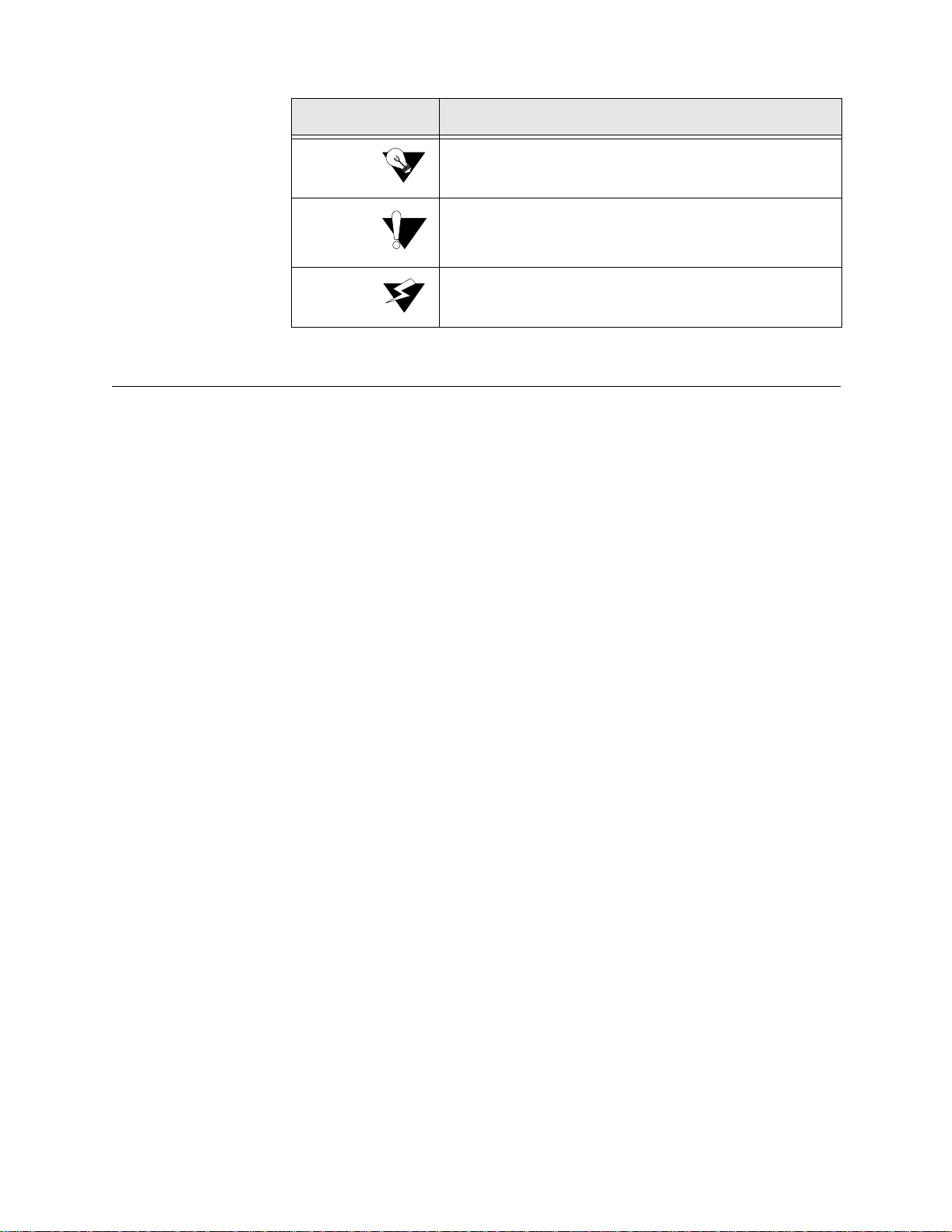
Convention Description
A Notice calls attentions to important feature s or instructions .
A Caution alerts you to s erious risk of data loss or othe r
results that may c aus e you or the unit trouble i f the warnin g is
not heeded.
A Warning a lerts you t o the risk of serious damage to the unit
or injury and possible death to the end user.
Customer Service and Technical Support
Verilink provides easy access to customer support through a variety of
services. Thi s section describes thes e services.
Support from Your DSL Service Provider
If assistance is required, contact your service provider. When you contact
your service provider for assistance, have the following information ready:
• Diagnostic error messages
• A list of system hardware and software, including revision le vels
• Details about recent configuration changes, if applicable
Support from Verilink
If you are unable to receive support from your service provider or want to
contact us directly, Verilink offers worldwide customer support by telephone,
e-mail, and through Verilink’s Internet Web site.
Telephone
Customer support is available by telephone 24 hours a day, 7 days a week. To
speak directly with a Verilink customer service representative, you may dial
one of the following numbers:
•Sales and Marketing: 800-VERILINK (837-4546)
•Technical Support: 800-285-2755 (toll-fre e)
You can request sales and marketing information or pose a technical support
question about your Verilink product by contacting us at the e-mail addresses
provided below. Verilink will respond to e-mailed requests for support during
regular business hours (8–5 CST, Monday–Friday).
1-256-32 7-2255 (int ernational)
xii WANsuite 6450
Page 13

•Sales and Marketing: info@verilink.com
•Technical Support: support@verilink.com
Internet
Visit Verilink’s Web site to access the latest Verilink product information,
technical publications, news releases, contact information, and more:
If this reference manual is revised to reflect code changes or other updates,
the most recent version will be posted to the Verilink Web site.
Returning a Unit to Verilink
If for any reason you must return your Verilink product, it must be returned
with the shipping prepaid, and pack aged to t he best commerci al stand ard for
electronic equipment. Verilink will pay shipping charges for delivery on
return. You are responsible for mode and cost of shipment to Verilink.
You must have a Return Material Authorization (RMA) number marked on
the shipping package. Products sent to Verilink without RMA numbers will be
returned to the sender unopened, at the sender’s expense.
http://www.verilink.com
A product sent directly to Verilink for repair must first be assigned an RMA
number. You may obtain an RMA number by calling Customer Service at
800-926-0085, extension 3002 (international number: 1-800-256-327-2255).
When calling Verilink for an RMA, please have the following information
available:
• Model number and serial numb er for eac h unit
• Reason for return and symptoms of problem
• Purchase order number to cover charges for out-of-warranty items
• Name and ph one number of per son we ca n contac t i f we have qu est ions abo ut
the unit(s)
The address for you to use when returning a unit to Verilink will be provided
when the RMA is issued. The standard delivery method for return shipments
is Standard Ground for domestic returns and International Economy for
international returns (unless otherwise specified).
Preface xiii
Page 14

xiv WANsuite 6450
Page 15

Introduction
C HAPTER
1
C
HAPTER
1
A
BOUT THE
Verilink’s WANsuite 6450 is a feature-rich, intelligent integrated access device
(IAD) that manages voice and data applications in an ATM network. The
WANsuite 6450 terminates a standards-based Symmetric High-Bit Rate
Digital Subscriber Line (SHDSL) that originates from a Digital Subscriber
Line Access Multiplexer (DSLAM) and provides interfaces for the end user’s
communications equipment.
WAN
SUITE
6450
The WANsuite 6450 is ServiceAware™ IAD with the following hardware: an
SHDSL network interface; a Constant Bit Rate (CBR) port configurable as T1
or E1; a Serial port software-configurable for V.35, V.36, X.21, RS-232, RS449, or EIA-530; a 10/100Base-T Ethernet port; an asynchronous Supervisory
port; five tri-color status LEDs; and front panel reset and factory
configuration buttons.
The Circuit Emulation Service (CES) support provides for the encapsulation
of TDM traffic from end-user equipment into ATM cells for transport across
the WAN to the DSLAM and on to the ATM network. This allows for the
continued use of existing TDM equipment at the premise while the ATM
network continues to grow and move further out to the edge. This unit
supports CES over the CBR port and the Serial port.
A router or bridge using PPP/HDLC protocols connects to the WANsuite
6450’s Serial port. The unit encapsulates the PPP data into ATM cells using
Internet Engineering Task Force (IETF) RFC 1483. Any router/bridge
supporting PPP over ATM (PPPoA) R FC 1483 encapsulation can be used at
the other end of this ATM connection.
The IP Gateway feature enables IP packet routing throughout a LAN/WAN
network architecture using static routing configuration or dynamic routing
protocols (Routing Information Protocol − RIP 1 and RIP 2, or Open Shortest
Path Fir st − OSPF), Dynamic Host Communications Protocol − DHCP, and
Network Address Translation − NAT.
RIP 1 and RIP 2 allow routers to exchange routing information. The
WANsuite 6450 then uses this information exchange to build routing tables
About the WANsuite 6450 1-1
Page 16

for IP Packet routes. After building the routing tables, the unit periodically
broadcasts the contents to neighboring routers so your network can choose the
most efficien t routes a vailable .
OSPF uses link-state routing algorithms to calculate routes based on the
number of routers, transmission speeds, delays, and route costs. Using the
OSPF protocol, the WANsuite 6450 works with other routers in your
telecommunications fabric to dynamically change routes “on the fly” to make
use of the most effici ent and cost-effecti ve transit across y our netw ork.
Bridging separate LANs together is another option for the IP traffic. Using the
IEEE Standard 802.1D Transparent Bridging specification, the WANsuite
6450 can simplify your network architecture by allowing you to bridge
separate LANs across a WAN so they operate as a single LAN.
Because IP Gateway enables the WANsuite 6450 to route IP traffic either
statically or dynamically or to bridge IP traffic across your LAN/WAN
architecture, your need for costly routers is substantially reduced. This onestop solution can help you meet the requirements of your many different
applications.
DHCP uses a server-client architecture to assign IP Addresses to PCs and
workstations on the LAN. The DHCP server dynamically assigns these IP
Addresses, which can be either temporary or permanent, to each PC or
workstation (DHCP client). These IP Addresses are "housed" on the DHCP
server. The flexibility to reassign IP Addresses saves the end user money by
eliminating the need for a single IP Address for each piece of equipment on
the LAN.
NAT enables an enterprise to set up two sets of IP Addresses − one s et for
internal network use (or LAN traffic) and one set for external use (or Internet
traffic). This can provide a layer of security for a company by eliminating
outside a ccess to in ternal IP Addres ses from t he Int ernet.
The WANsuite 6450 gives service providers and enterprise customers the
capability to monitor end-to-end network performance (with support of up to
16 virtual channels); isolate performance problems to the LAN, local loop, or
ATM network; determine appropriate bandwidth needs; and monitor network
trends to aid in future capacity planning.
All of the WANsuite 6450’s installation, performance configuration, traffic
monitoring, alarm reporting, and diagnostic capabilities can be configured
through the unit’s embedded Web server interface (WANsight™) using
Microsoft
®
Internet Explorer™ . The Web server interface can be a ccessed
locally through the Ethernet port or the Supervisory port, or remotely through
the Network port. Especially advantageous is WANsuite’s advanced
monitoring and control capability that gives network administrators the ability
to plan future capacity requirements.
The unit’s built-in Service Aware technology lets network managers maximize
available WAN bandwidth and verify SLAs. This management platform lets
the end user see network activity (performance) and problems (diagnostics) on
any permanent virtual circuit (PVC), access line, or physical circuit.
1-2 WANsuite 6450
Page 17

Features of the WANsuite 6450
Performance
Historically, WAN access devices have tended to perform well as singlefunction devices such as CSU/DSUs, but have not been optimized to address
higher-level traffic issues such as service levels and integration. Verilink's
architectur e and Web-based us er interfac e work together to address all acce ss
issues such as services and applications, rather than as circuits and protocols,
for except ional WAN managemen t performan ce.
To further leverage its Web browser interface, Verilink's new architecture also
allows firmware to be upgraded via the Web from a standard browser, with
password control, if desired.
SNMP Management
With integrated SNMP in-band management, enterprise managers can now
manage Verilink WANsuite units and their integral CSU/DSUs as a single
unit. With only one LAN segment in the network, the WANsuite 6450 can be
managed by SNMP. By downloading all configuration parameters from the
central site, no interaction is required at remote sites to establish connectivity.
The unit allows any port to be configured for any of its available service
technologies through simple software configuration. Network managers can
now fine tune the enterprise network for the lowest cost and highest
performance.
Intelligent WA N Access Architecture
Verilink's next-generation WAN access architecture is built around a
PowerPC™ processor with 50 MIPS of processing power and 16 Mbytes of
onboard memory, and works with non-proprietary network management
solutions via SNMP. An embedded Web server supplies a simple-to-use
interface for configuration and statistics collection, with a service table for
mapping services to ports and a user table for monitoring and controlling
traffic.
Overview and Advantages
Verilink’s WANsuite 6450 is an innovative, highly intelligent, software-based
WAN access device optimized for ATM over G.shdsl access. This unit
provides network managers with all the tools necessary to monitor and
troubleshoot voice, data, and network transmission systems. The ability to use
the WANsuite 6450 unit as an IP Gateway greatly increases its flexibility,
while reducing networking costs. In addition, the WANsuite 6450 is a
valuable tool for the following:
• Measuring and reporting performance
About the WANsuite 6450 1-3
Page 18

• Managing network resources to ensure optimum performance
• Analyzing trends to aid in network planning
WANsuite 6450 advantages include the following:
• Enables a new class of xDSL technologies − the internationally standard
G.shdsl.
• Allows for continued use of existing TDM equipment by support ing CES via
AAL1.
• Reduces the need for cos tly r outers with its IP Gateway feature.
• Offers easy install ation and configu rati on, reducing maintenanc e and sparing
costs.
• Controls recurring ATM access costs − WANsuite products quickly pay for
themselves by allowing enterprises and service providers to optimize the use
of valuable bandwidth.
• Allows for use of existing routers without changing the ext ernal router’s
configuration by running PPP over an ATM network.
Features Summary
• Powerful core architecture
• SHDSL network port for symmetrical data rates r anging from 192 kbps to
2.312 Mbps
• T1 or E1 circuit emulation
• 10/100Base-T Etherne t port and asynchronous Supervi sor y port
• Serial data port , use r-selectable V.35, V.36, RS-232, or EIA-530
• Intuitive Web browse r for management
• CES
• Constant Bit Rate (CBR) port configurable for T1 or E1 supporting the
following modes:
• Unframed T 1 − 1.544 Mbps raw bit stream
• T1 ESF
• T1 D4
• Unframed E1 (G.703) framing − 2.048 Mbps raw bit stream
• E1 CCS framing
• E1 CAS framing
• AAL1 ATM encapsulation
• Structured Nx64 basic servic e supporting full or partial T1/E1 circuits
1-4 WANsuite 6450
• Structured Nx64 servic e with Channel Associated Signaling (CAS)
supporting the following:
• E1 CAS signaling
• T1 robbed bit signaling
Page 19

• Full or partial T1/E1 circuits with signaling
• Unstructured servi ce (2.048 Mbps E1 or 1.544 Mbps T1)
• Configurable for synchronous or adaptive timing
• User configurable Cell Del ay Variation
• User configurable partial cell fill
• User configur able sc rambling/ descra mbling of ATM cell Payload us ing an
43
x
+1 polynomial
• User configurable time slot multiplexing between the CBR port and the
Serial port
• For Nx64 basic and CAS services, the user can individually configure
the CES channels for the CBR port or for the Serial port
• For Unstructured E1 service , the user can co nfigure all channels for
either the CBR port of for the Serial port
• IP Gateway
• 10/100Base-T Ethernet port
• Static routes
• Static Address Resolution Protocol (ARP)
• Dynamic routing proto cols, including RIP 1, RIP 2, and OSPF
• Un-numbered network
• Address Management: NAT and DHCP
• Bridging
• Programmable alarm thresholds
• IPoA
• Serial Port Configurab le for PPP or CES
• Supports V.35, V.36 , EIA-530, or RS-232
• PPPoA
• Management Interf aces
• WANsight − an innovative Web-based user interface
• Embedded HTTP server for remote configu ration and real-time
reporting via Web browser
• Decreased installa tion and configuration time for ser vice employees
• Simplified trouble shooting and fault isolation of network problems
• Optimal management of ATM-based servic es
• Saves and downloads configur ation files from remote server
• EOC for SHDS L-rel at e d para meters
• SNMP
• VT100
About the WANsuite 6450 1-5
Page 20

Front Panel
The front panel of the WANsuite 6450 is shown below in Figure 1.1.
Figure 1.1
Front Panel of WANsu ite 6450
The front panel’s five LED status indicators are described below:
Indicator Description
MODE
CBR
NET
ALARM
POWER
Normally, this indicator lights green.
The indi ca tor light s amber while con figuratio n is being set by th e front panel
buttons or when the configuration is changed by SNMP or through the Web
interf a ce . T he ind i cator will remain amb e r un t il th e ch anged con f iguratio n is
saved; it will revert to green when the new configuration has been saved.
The indicator i s off (not illuminated) when t he CBR port has not been
configured.
The indi ca tor light s green when the CBR port link is up and is receivi ng AAL1
cells.
The indi ca tor light s red when the CBR port has been configu red and no AAL1
cells ar e receiv ed.
The indicator lights amber when the CBR port link is up but AAL1 cells are not
being rec eived.
The indicator is off (not illuminated) when the Network port has not been
configured.
The indi ca tor light s green when the Network port l ink is up and the ATM
protocol is established.
The indi ca tor light s red when the Network port link is dow n and the ATM
protocol is not established.
The indi ca tor light s amber when the Network port link is up, but the ATM
protocol is not established.
The indi ca tor light s red if an alarm condition exists.
The indi ca tor light s amber if a “yellow” alarm condition exists.
The indi ca tor light s green when power is applied to the unit.
The indi ca tor light s amber when the unit is in a test mode loop back.
1-6 WANsuite 6450
The user-activated input control buttons are described below:
Button Description
RESET
CONFIG
*The CONFIG button must be held until the MODE LED lights amber and remains illuminated for the
default config ur at io n to tak e effect.
Provides a hardw are reset to the u n it.
Sets the unit back to its factory defa ult Ethernet or HD LC configuration; this is
the same as a maintenance reset.
To initia te thi s fu n ction, you m u st pre ss an d ho ld th e
power-up sequence.*
CONFIG button during a
Page 21

Rear Panel Connections
The rear panel of the WANsuite 6450 has five connectors. From left to right,
these are a s follows :
SERIAL
, CBR, and NETWORK as shown in Figure 1.2 below.
POWER, SUPERVISORY PORT, 10/100 ETHERNE T,
Power Port
Figure 1.2
The POWER port on the WANsuite 6450 unit is a standard, grounded, threeprong connector. This 110/220 VAC power receptacle is rated at 50–60 Hz,
0.2 A/0.1 A. To apply power to the unit, simply plug the supplied power cord
into the unit’s
electrical outlet. The unit has no power switch.
When power is applied to any WANsuite 6450 unit, the front panel indicators
flash for approximately 10 to 15 seconds as the unit initializes. The green
POWER LED on the front panel will remain illuminated as long as the unit
receives power. This LED turns amber when the unit is in test mode.
WANsuite 6450 Rear Panel
POWER port and then connect the wall plug to an appropriate
CAUTION: Always connect the power cord to a grounded electrical outlet.
Supervisory Port
NOTICE: Per UL 1950 and CSA 60950 Clause 1.7.2, if the power supply cord is
intended to serve as a disconnect device, an easily accessible socket
must be installed near the equipment.
Power Failure
If the indicator does not illuminate, check the power connections and the
primary circuit breaker.
The WANsuite 6450 units provide nonvolatile memory retention of the unit
configuration in case of a power failure. The unit will automatically restore
normal service following a power loss and will retain pre-existing time and
date information.
The SUPERVISORY port is a DB-9 female D CE c onnector co nfigure d for 8
bits, no parity, and 1 stop bit. Bit rates are configured through the Web server
interface. (S ee Unit Access Details on page 3-24.) The Supervisory port speed
About the WANsuite 6450 1-7
Page 22

can be set to 1200, 2400, 4800, 9600, 19200, 38400, 57600, or 115200 bps.
The initial default rate of the Supervisory port is 19200 bps.
On power-up, the Supervisory port sends out diagnostic messages at the bit
rate of 115.2 kbps until the Supervisory service acquires the Supervisory port,
after which the port speed is changed to the setting in the Supervisory
interface s creen.
NOTICE: For information on pinout assignments for this connector, refer to
10/100 Ethernet Port
The WANsuit e 64 50 pr ovi des a sing le 10/100 ETHERNET interf ace port for IP
Gateway, SNMP, and Web browser access. This interface is an eight-pin
modular jack that complies with standard twisted-pair, 10/100Base-T
requirements. The 10/100Base-T cable is supplied by the end user. Refer to
Ethernet Connection Pin Assignments on page A-8 for pin assignments and
cable descriptions.
Ethernet LED Indicator s
Supervisory Port Pin Assignments on page A-9. See Standard
Equipment on page A-4 for information on cables for this connector.
Serial Port
There are two unlabeled indicator LEDs on either side of the 10/100 Ethernet
jack. The LED on the left side of the jack pulses amber to indicate data
activity (either transmit or receive). The LED on the right side of the jack
lights green to indicate that the link layer is operational.
The SERIAL interface port located on the WANsuite 6450 rear panel is a
multi-protocol interface presented physically as a DB-25 connection. The
protocols supported by this interface are RS-232, V.35, V.36, EIA-530, X.21,
and RS-449.
Cables that adap t the DB-25 interface to the 34-pin V.35 interface are
available. DB-25 to DB-25 cables are also available if your installation needs
require them. See Standard Equipment on page A-4 for details. Pin
assignmen ts for the Serial i nterface a re listed in Serial Interface Pin
Assignments, DTE Mode (Packet Use Only) on page A-6 and Serial Interface
Pin Assignments, DCE Mode on page A-7.
CAUTION: FCC rules require that interconnecting cables carrying high-speed
data be shielded appropriately to minimize radio frequency
interference.
1-8 WANsuite 6450
Page 23

CBR Port
Network Port
CAUTION: The T1/E1 CBR port is not a standalone port. Connect the T1/E1 CBR
port only to the "private" side of the network on the customer
premises, never to the "public" side.
The CBR interface port located on the WANsuite 6450 rear panel is an
RJ11C, eight - pin modular jack that can be software-selectable for T1 or E1.
As a T1 port, it terminates as 100 ohms, and as an E1 port at 120 ohms. This
port is used to transport TDM traffic using a T1/E1 framer to provide ATM
adaptation Layer 1 with Circuit Emulation Services (AAL1-CES).
To view the pinout assignments for this interface, refer to CBR Interface Pin
Assignments on page A-8.
The WANsuite 6450 has one rear panel NETWORK interface port. This
connection is a standard RJ11C, eight-pin modular jack that terminates as 135
ohms.
To view the pinout assignments for this interface, refer to Network Interface
Pin Assignments on page A-8.
About the WANsuite 6450 1-9
Page 24

1-10 WANsuite 6450
Page 25

This chapter describes the contents of your WANsuite 6450 shipment and
provides information on connecting and installing the unit.
The WANsuite 6450 uses an “Installation Wizard” to help you automatically
install the unit quickly and correctly. Procedures for using this Installation
Wizard are also describe d in this c hapter.
Unpacking and Inspection
C HAPTER
2
C
HAPTER
2
I
NSTALLATION
The WANsuite 6450 is shipped in cardboard cartons with foam inserts for
shock and vibration protection. When your shipment arrives, inspect the
shipping container and contents, and compare all items with those on the
packing list.
If the contents of the shipment are incomplete or if there is mechanical
damage or defect, notify Verilink. (Refer to Support from Verilink on
page xii.) If the shipping container or cushioning material is damaged, notify
the carrier and Verilink immediately and make a notation on the delivery
receipt that the container was damaged. (If possible, obtain the signature and
name of the person making delivery.) Retain the packaging material until the
contents of the shipment have been checked for completeness and the unit has
been check ed both m echani cally and electrical ly.
Supplied Materials
The WANsuite 6450 ships with the following standard items:
• Serial (Super visory) cable
• Network cable
• Power cord
• Verilink Documentation CD
Installation 2-1
Page 26
For specific applications, see Connector Pin Assignments on page A-6 for
additional optional cables and adapters. Contact Verilink Technical Support
(page xii) for furthe r assistan ce.
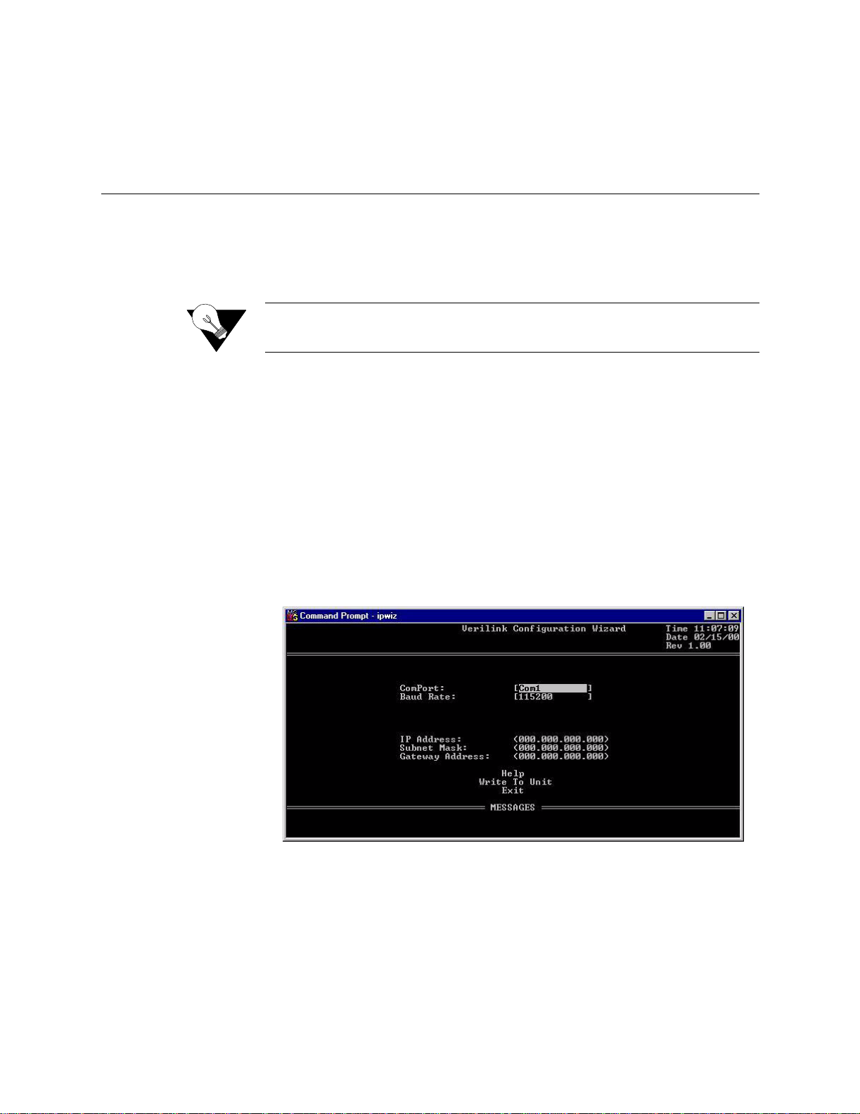
Installation Wizard
The WANsuite 6450 can be configured and monitored through the Web server
interface. To gain access to this interface, the unit must be configured with an
IP Address. Verilink provides a DOS-based program – the Verilink
Configuration Wizard – to aid in this initial configuration.
NOTICE: You may also access the Verilink Configuration Wizard on the
To configure the IP Address using the Verilink Configuration Wizard, perform
the following steps:
1 Using the supplied cable, connect the unit’s DB-9 Supervisory port to a
COM port on your PC. (Take note of which COM port is connected.)
2 Insert the Verilink CD (provided with the WANsuite 6450) into your PC’s
CD-ROM drive.
Verilink We b site: www. verilink.com.
3 Use Windows “Explore” to view the contents of the CD and select the
folder labeled “Utilities.” In this folder will be a file named
this executable fil e is the Verilink Configuration Wizard application.
Double-click on this file to launch the program. After the program is fully
launched, you will see the following screen:
ipwiz.exe;
4 Using the Tab key to move fr om field t o fie ld, move the cursor to the “COM
Port” field. Using the Spacebar, toggle between the available options until
the correct COM port is sho wn (COM1, COM2, COM3, or COM4). Be s ure
to choose the same COM port as the port to which the unit is connected.
2-2 WANsuite 6450
5 By default, the “Baud Rate” field will display 115200 (bits per second). For
the purpose of this installa tion, do not change the displayed baud rate from
its default. Proceed directly to the next step.
Page 27

6 Using the Tab key again, move the cursor to the “IP Address” field and
enter the appropria te IP Address for the unit (xxx.xxx.xxx.xxx). If necess ary ,
repeat this process for the “Subnet Mask” and “Gateway Address” fields.
7 Next, move the cursor to the “Write To Unit” field and press the Enter key.
The program will prompt you to reset the unit.
8 To reset the unit, press the RESET button on the unit’s front panel. The
Configuration Wizard will then automatically download the confi guration
information to the unit.
9 Note the status messages displayed at the bottom of the Configuration
Wizard screen. When the download is complete, your PC will beep and the
status message bar will displa y “Finished.”
10 Finally, move the cursor to the “Exit” prompt and press Enter. The
Configuration Wizard pr ogram will close.
Installation 2-3
Page 28

2-4 WANsuite 6450
Page 29

C HAPTER
3
C
HAPTER
3
W
EB
S
ERVER INTERFACE
The WANsuite 6450 has an innovative, embedded Web-based user interface
(WANsight) for remote configuration and real-time reporting via Microsoft
Internet Explorer 5.0 or higher. Access to the Web server interface and how
the interface is used to configure the WANsuite 6450 unit are described in
detail below.
NOTICE: Verilink recommends the use of Microsoft’s Internet Explorer 5.0 or
higher because if you use other Internet browsers to access the Web
server interface , some screen elemen ts will not disp lay as describe d in
this manual.
NOTICE: The material presented in this chapter follows the order listed in the
navigation bar on t he left side of the Web Server interface screen.
However, because the parameters you specify in the Service Table
attach proto cols to inter faces , you m ust c onfig ure t he Serv ice Table
first. (See Services as described on page 3-25.) You will not be able to
allocate channels (see Channel Table Details Screen as described on
page 3-37) un til the Service Table has been configured.
Configuration through the VT100 interface is covered in Chapter 4.
Web Server Interface 3-1
Page 30

Web Server Access
You can access the Web Server interface by connecting to its IP address. This
connection can be directly through the 10/100 Ethernet port, in-band via PPP
over any port, or in-band via encapsulated IP traffic on the ATM WAN
circuit.
NOTICE: Any changes to the unit’s configuration MUST be followed by a
“Submit” if there is a “Submit” button on the menu. If you
change the Service Table, you must perform a “Save and
Restart.”
To access the Web Server interface, type th e unit’s IP address in the
browser’s Address (or Location) field and press the “Enter” key.
Layout of Interface Screens
When you first access the Web Server interface, your browser will display a
screen that is divided into three frames. The upper frame forms a border
across the top of the screen; it identifies the Verilink unit in service and
displays the hardware and software revision and serial numbers under which
the unit is operating. The far right corner of the upper frame displays whether
or not a “Save an d Restar t” is nece ssary when param eters are change d on the
currently displayed screen.
Unit Screen
The area beneath the upper frame is divided into two side-by-side frames. The
frame on the left side of t his area d epicts a hierarch ical “tree” structure used
to navigate through the various interface screens. Each “branch” on the tree
guides you to more specific upper-level information about the unit and its
configuration. Note that the Interfaces, Applications, and Utilities branches do
not link to a page − these branches simply provide structure for navigation.
The frame on the right side of the screen will display the actual configuration
screen. The screen captures throughout this chapter show only the
configurat ion portio n of the screen, except in t he case of the Un it screen ,
which sh ows all t hree frames . The Un it scr een represe nts the to p of the
navigation tree.
The first screen displayed by the unit’s Web Server interface is the Unit
screen (Figure 3.1). This screen lets you view and set specific information
about the unit in service.
3-2 WANsuite 6450
Page 31

Figure 3.1
Unit Screen
The Unit screen displays the following fields:
Field Function
Object ID Display-only field used to point an SNMP agent to this ID.
Up Time Displays the amount of tim e the unit has been up and running.
Contact Stores the name of a point-of-c ontact for system failure.
Name Read/write field that holds the uni t’s name.
Location Read/write fiel d that holds the unit's location.
FrameStart ID Not used for ATM. Read/write field that holds the unit' s ID tha t
uniquely identifies the unit and is used in the FrameStart
applications.
Blank Fields Read/write fields for user-specific labels and values. Information
resides in non-volatile memory.
Time Read/write fie ld tha t hol ds th e unit' s int ernal t ime s ett ing i n standa rd
24-hour HH:MM:SS format.
Date Read/write fiel d that hol ds the unit' s i nter nal dat e s ettin g in st andar d
MM/DD/YY format.
The Unit screen provides the following user-activated buttons:
Button Function
Submit Sets any values that have been changed. Use th e top “Submit”
button to set unit parameters changed in the upper section of the
screen, and the lower “Submit” button to set the re al-time clock.
Web Server Interface 3-3
Page 32

Button Function
Maintenan ce Reset Resets unit to its default configurat ion.
Save and Restart Saves the c urrent configuration and restarts the unit.
Maintenance Reset
Use this button to perform a Maintenance Reset. All configurations will be
lost and the unit will be set back to an initial factory configuration. There are
five options for a Maintenance Reset as shown in the table below.
RFC 1483
Configuration
Choice
Ethernet Yes Yes No None None None
Serial HDLC Yes No Yes None None None
T1 CBR* Yes No Yes 1−24 None None
E1 CBR Yes Yes No None 1−31 None
Serial CES
Configuration
* Factory default configuration
Encapsulated
Data
Yes Yes No None None 1−31
IP
Encapsulated
in ATM
Serial HDLC
Encapsulated
in ATM
T1 CBR
Channels
E1 CBR
Channels
Serial CBR
Channels
All the factory configurations set up an ATM service on the Network port
with one configured virtual channel (VPI=0, VCI=32). Management data
received on this channel (either WEB or SNMP) will be processed at the unit
if it is encapsulated using RFC 1483 and directed to the unit’s IP address. (A
Maintenance Reset will not change the unit’s IP address.)
The Serial HDLC configuration and the T1 CBR configuration will also
accept PPPoA encapsulated data and deliver it to the Serial port.
The T1 CBR, E1 CBR, and Serial CES configurations set up a CES service
between the Network port and the T1/E1 CBR port or the Serial port using
VPI=0, VCI=33. The T1 CBR configuration sets up the CBR port to run T1
and has 24 channels delivered to the CES service. The E1 configuration sets
up the CBR port to run E1 and has 31 channels delivered to the CES service.
The Serial CES configuration sets up the CBR port to run E1, but allocates
Channels 1 −31 to the Serial port.
3-4 WANsuite 6450
Clicking the “Maintenance Reset” button will display a selection screen with
a drop-down list of the available configurations as shown in Figure 3.2
Page 33

Figure 3.2
NOTICE: Performing a “Maintenance Reset” or a “Save and Restart” will
Save and Restart
Maintenance Reset Screen
terminate communications with the unit.
Interfaces
The Save and Restart button on the Unit screen will display the confirmation
screen shown in Figure 3.3.
Figure 3.3
Click the “Save and Restart” button on the confirmation screen to proceed
with the action. To cancel, simply invoke your browser’s “Back” function.
The WANsuite 6450 unit has five available interfaces: Network, CBR, Serial,
Ethernet 10/100, and Supervisory. These interfaces are described below.
Save and Restart Screen
Network
The WANsuite 6450 Network screen (Figure 3.4) lets you view and make
changes to the Network interface's configuration.
Web Server Interface 3-5
Page 34

Figure 3.4
Network Screen
The Network screen status and configuration parameters are described in the
following paragraphs.
Unit Type
Expected Repeaters
Span Configuration
Span Alarm
Configuration
Selects the unit type. TU-R represents a CPE terminal unit; TU-C represents a
CO te rmina l unit .
Values: TU-R, TU-C
Default: TU-R
Provisions the num ber of re peaters in the sel ected s pan.
Values: 0 (zero )
Default: 0 (zero)
Represents a span configuration profile in the Span Configuration Profile
Table, which applies to this span. By default, this object will have the value
“DEFVAL” (the index of the default profile).
Values: User Span Profile 1, User Span Profile 2, DEFVAL (Default
Value)
Default: DEFVAL
Represents an Alarm configuration profile in the Endpoint Alarm
Configuration Profile Table. The alarm threshold configuration in the
referenced profile will be used by default for all segment endpoints in this
span. By default, this object will have the value 'DEFVAL' (the index of the
default profile).
Values: User Alarm Profile 1, User Alarm Profile 2, User Alarm
Profile 3, DEFVAL (Default Value)
Default: DEFVAL
Pair-1 Mode
3-6 WANsuite 6450
Represents the status and detail status information of the span for two-wire
operation.
Page 35

Pair-2 Mode
Represents the status and detail status information of the span for four-wire
operation. This mode is not supported by the WANsuite 6450.
EOC In
EOC Out
Discovered Repeaters
Line Rate
Maximum Line Rate
Transmission Mode
Displays the number of messages received on the Embedded Operations
Channel.
Displays the number of messages transmitted on the Embedded Operations
Channel.
Displays the number of discovered repeaters in this span.
Displays the actual negotiated line rate.
Displays the maximum physical line rate.
Displays the actual transmission mode (Annex-A or Annex-B).
The Network screen provides the user-activated buttons described below.
Button Function
Submit Sets any values that have been changed.
Configuration Pr ofiles Displays the three configuration profiles that can be used.
Alarm Profiles Displays the four alarm profiles that can be used.
Span Endpoints Lists the currently availab le span endpoints.
CAUTION: Performance data will be lost upon power cycle or after performing a
Maintenance Reset/Restart.
Configuration Profile Table Screen
Clicking on the “Configuration Profiles” button on the Network screen will
display the table shown in Figure 3.5.
Figure 3.5
This table displays the information the user specifies in the Configuration
Profile Details screen (Figure 3.6), which is accessed by clicking on the
specific Profile Name hyperlink in the table above.
Configuration Profile Table Screen
Web Server Interface 3-7
Page 36

Figure 3.6
Configuration Profile Det ails Screen
This screen lets you configure or change the following information about the
selected configuration profile:
Wire Mode
Data Rate (Min)
Data Rate (Max)
Remote
Transmission Mode
Displays the type of wire interface used by the span. The WANsuite 6450
supports only the two-wire mode.
Sets the minimum attainable data rate in the span.
Sets the maximum attainable data rate in the span. Note that the line rate will
be 8 kbps above the data rate.
Enables/disables support for remote management of the units in an SHDSL
line from the STU-R via the EOC.
Values: Enabled, Disabled
Default: Enabled
Sets the regional setting of the span represented as a bit-map of possible
settings.
Values: Annex-A ( ITU-T G.991.2), Annex-B (ITU-T G.991.2)
Default: Annex-B
NOTICE: When the WANsuite 6450 is operating with Unit Type set to TU-R, it
supports Annex-A or Annex-B. The configuration of the TU-C unit
determines the actual transmission mode used.
PSD Type
Line Probe
3-8 WANsuite 6450
Sets the use of symmetric Power Spectral Density (PSD) mask.
Values: Symmetric
Default: Symmetric
Enables or disables rate adaptation line probe.
Values: Enabled, Disabled
Default: Enabled
Page 37

To set any configuration profile parameter, enter the desired value/information
in a field or select the desired parameter from one of the pull-down lists, and
then click on the “Submit” button.
Alarm Profile Table Screen
Clicking on the “Alarm Profiles” button on the Network screen will display
the screen shown in Figure 3.7.
Figure 3.7
Alarm Profile Ta ble Screen
The Alar m Profiles screen d isplays the cur rent values of SHDS L alar m
thresholds. Click on the specific hyperlink under “Profile Name” to configure
the alarm threshold values to be used for the selected segment endpoint in the
“Alarm Profile Details” screen shown in Figure 3.8.
Figure 3.8
Alarm Profile Details Screen
Loop Attenuation
SNR Margin
ES
Sets the loop attenuation alarm threshold. If the current value reaches or
exceeds this threshold, a crossing trap is generated. A value of 0 (zero)
disables the trap.
Sets the Signal-to-Noise Ratio margin alarm threshold. When the current SNR
value reaches or drops below this threshold, a crossing trap is generated. A
value of 0 (zero) disables the trap.
Sets the threshold for the number of Errored Seconds within any given 15minute performance data collection interval. If the value of ES in a particular
Web Server Interface 3-9
Page 38

15-minute collection interval reaches/exceeds this value, a trap is generated.
One trap will be sent per interval per endpoint. A value of 0 (zero) disables
the trap.
SES
CRC
LOSWS
UAS
Sets the threshold for the number of Severely Errored Seconds within any
given 15-minute performance data collection interval. If the value of SES in a
particular 15-minute collection interval reaches/exceeds this value, a trap is
generated. One trap will be sent per interval per endpoint. A value of 0 (zero)
disables the trap.
Sets the threshold for the number of Cyclic Redundancy Check anomalies
within any given 15-minute performance data collection interval. If the value
of CRC anomalies in a particular 15-minute collection interval reaches/
exceeds t his value , a trap is generated . One trap will be sent p er interv al per
endpoint. A value of 0 (zero) disables the trap.
Sets the threshold for the number of Loss of Sync Word Seconds within any
given 15-minute performance data collection interval. If the value of LOSW
in a part icular 15-m inute co llection in terval reaches/ex ceeds this value, a trap
is generated. One trap will be sent per interval per endpoint. A value of 0
(zero) disables the trap.
Sets the threshold for the number of Unavailable Seconds within any given
15-minute performance data collection interval. If the value of UAS in a
particular 15-minute collection interval reaches/exceeds this value, a trap is
generated. One trap will be sent per interval per endpoint. A value of 0 (zero)
disables the trap.
NOTICE: Any changes to the above-listed parameters must be followed by a
“Submit” for the changes to take effect.
Span Endpoints Screen
Clicking on the “Span Endpoints” button on the Network screen will display
the screen shown in Figure 3.9.
Figure 3.9
This screen displays each endpoint of the span. If the SHDSL link is not up,
only the local side of the span is displayed. The EOC channel is used to
access th e remote end uni t
Clicking on the highlighted (linking) Type identifier in the table on the Span
Endpoints screen will display the Span Endpoints Details screen (Figure 3.10).
This table supports retrieval of unit inventory information available via the
Span Endpoint Table Screen
3-10 WANsuite 6450
Page 39

EOC from units on an SHDSL line, and provides details regarding the
paramete rs listed be low.
Vendor ID
Model Number
Figure 3.10
Span Endpoint Details Screen
Displays the Vendor ID as reported in an Inventory Response message.
Vendor model number as reported in an Inventory Response message.
Serial Number
EOC Software Version
Standard Version
List Number
Issue Number
Software Version
Equipment Code
Transmission Mode
Capabilit y
Endpoint Side
Vendor serial number as reported in an Inventory Response message.
Vendor EOC version as reported in a Discovery Response message.
Version of the SHDSL standard implemented as reported in an Inventory
Response message.
Vendor list number as reported in an Inventory Response message.
Displays the Vendor issue number as reported in an Inventory Response
message.
Displays the Vendor software version as reported in an Inventory Response
message.
Equipment code conforming to ANSI T1.213, Coded Identification of
Equipment Entities.
Transmission mode capability of the SHDSL unit.
Defines which direction the SHDSL port is pointing. Normal operation will
use the TU-R configuration, and the endpoint will be “Network.” When unit
type is TU-C, endpoint will be “Customer.”
Wire Pair
Always “Wire Pair 1.”
Web Server Interface 3-11
Page 40

Clicking on the “Span Endpoint Performance/Summary” button on the Span
Endpoint Details screen will display the screen shown in Figure 3.11.
Time Elapsed
ES
CRC
Figure 3.11
Span Endpoint Perf ormance/Summary Screen
This screen display s inform atio n on the pe rform ance an d error st atus of a s pan
endpoint. This information is provided in summary form for complete totals
as well as for current 15-minute and 1-day intervals.
Total elapsed seconds in the current 15-minute interval.
Count of Errored Seconds on this endpoint since the unit was last restarted.
Count of Cyclic Redundancy Check anomalies on this endpoint since the unit
was last restarted.
LOSWS
SES
UAS
Count of Loss of Sync Word Seconds on this endpoint since the unit was last
restarted.
Count of Severely Errored Seconds on this endpoint since the unit was last
restarted.
Count of Unavailable Seconds on this endpoint since the unit was last
restarted.
15-Minute and 1-Day Intervals
Also included on this screen are buttons used to display the span endpoint
performance summaries for 15-minute intervals and for 1-day intervals. These
screens display only a summary of the errors (ES, SES, CRC, LOSWS, UAS)
that have occurred on the span during the interval selected.
The 15-Minute Intervals table provides one row for each endpoint
performance data collection 15-minute interval. The 1-Day Intervals screen
provides one row for each endpoint performance data collection 24-hour
interval.
Span Endpoint Maintenance Screen
Clicking on the “Span Endpoint Maintenance” button from the Span Endpoint
Details screen will dis play the screen shown in Figure 3.12. This table suppor ts
maintenance operations (e.g., loopbacks) to be perform ed on segment
endpoints.
3-12 WANsuite 6450
Page 41

Figure 3.12
Span Endpoint Maintenance Screen
The Span Endpoint Maintenance parameters are described below.
Tip Ring Reversal
Loopback Timeout
Restart Endpoint
Power Source
CBR
Loopback
(minutes)
Specifies loopbacks for the associated segment endpoint.
Values: No Loopback, Normal Loopback
Default: No Loopback
Indicates the state of the tip/ring pair at the associated segment endpoint.
Specifies the timeout value in minutes for loopbacks initiated at this endpoint.
A value of 0 disables the timeout.
Enables the manager to trigger a soft restart of the SHDSL line at the
associated segment endpoint. Set this object to “restart” to initiate a restart. A
restart will occur after approximately 5 seconds.
Values: Ready , Restart
Default: Ready
Indicates the DC power source being used by the associated unit.
CAUTION: The T1/E1 CBR port is not a standalone port. Connect the T1/E1 CBR
port only to the "private" side of the network on the customer
premises, never to the "public" side.
Click on the CBR link on the navigation pane on the left-hand side of the
Unit screen to display the CBR screen (Figure 3.13). The CBR screen (Figure
3.13) lets you view and make changes to the CBR interface’s configuration as
described below. In addition, this screen provides a table that displays error
status and alarm thresholds for the CBR int erface.
Web Server Interface 3-13
Page 42

Figure 3.13
CBR Screen
T1/E1 Framing
T1/E1 Coding
T1 PRM
Selects the framing for the network side of the DSU/CSU.
Values T1 ESF, T1 D4, E1 CCS, E1 CAS
E1 Unframed, T1 Unframed
Default: E1 CCS
NOTICE: To set unit to Signaling mode, you must first configure the following: on
the CBR screen (page 3-13), configure Framing; on the Channel Table
Details screen (page 3-37), set Rate to 56k/Signaling, and on the CES
Service Details screen (page 3-34), configure AAL1 Format.
Sets the CBR interface line coding.
Values: HDB3, AMI, B8ZS
Default: HDB3
NOTICE: For a T1 CBR Maintenance Reset, the default is T1 ESF. The T1/E1
coding default is B8ZS.
Lets you establish which performance messaging standard will be employed
to initiate Performance Report Message (PRM) functions. Setting this field to
“Enable” instructs the unit to use ANSI T1.403, which sends a PRM once
every second. Setting this field to “Disable” instructs the unit to use AT&T
TR54016, which provides performance reporting on request only.
Values: Disable, Enable
Default: Disable
3-14 WANsuite 6450
Page 43

T1 Zero Suppression
Determines whether ones density insertion is activated after 15 zeros. This
parameter is ignored if the Coding parameter is set to “B8ZS.”
Values: Disable, Enable
Default: Disable
T1 Mode
T1 Line Build Out
T1 DSX Level
E1 CRC4 Mode
As a T1, the unit will operate in either long-haul or short-haul mode.
Values: Short-Haul, Long-Haul
Default: Short-Haul
Sets the transmit Line Build Out (LBO) for the CBR interface.
Values: 0, −7.5, −15.0, −22.5 dB
Default: 0 dB
Specifies the T1 DSX output level.
Values: 0−110, 111−220, 221−330, 331−440, 441−550, 551−660, >661 ft
Default: 0−110 ft
Provides line integrity detection to determine if bit errors are present on the
line.
Values: Disable, Enable
Default: Disable
Error Status and Alarm Thresholds Table
The unit can be programmed to generate an alarm condition based on a
specific level of performance degradation. The CBR screen presents a table
that provides current error status and alarm threshold information.
Acceptable alarm thresholds are set for periods of 15 minutes (900 seconds)
and sampled every second. The error types listed in the following paragraphs
can be preset to a value between 0 and 900 seconds. Setting a field to “0”
(zero) dis ables the a larm on that st atistic. To effectiv ely disab le alarm
reporting , set all fields to “0” (zero).
The 15-minute time frame is not based on the TR 54016 or T1.403 interval
boundaries, but is a time window based on the accumulated counts over the
previous fifteen 1-minute intervals. In all cases, if the number of actual
network errored seconds in the previous 15 minutes reaches the preset
threshold for the specified error type, an alarm condition is declared.
The four columns o f the s tatus tab le are as follows:
• Status: Displays the current status of the CBR port.
• Alarm: Display s the alarm value of the network port. The unit declares an
alarm as soon as the count exceeds the threshold set.
• Count: Display s the number of events or occurrences of this stati stic that
have been dete cted .
• Threshold: Displays a read/write field that can be set to a desirable
threshold.
The table provides error sta tus and alarm thre shold in formation f or the
following error pa rameters:
Web Server Interface 3-15
Page 44

ES
Sets the Errored Seconds (ES) threshold. An ES is a 1-second period in which
at least one logic error occurred. The default value is 45 seconds.
SES
LOSS
UAS
CSS
BPVS
OOFS
AISS
Sets the Severely Errored Seconds (SES) threshold. An SES is a 1-second
period in which at least 320 CRC errors or one Out- of - Frame (OOF) error
occurred. The default value is 5 seconds.
Sets the Loss of Signal Seconds (LOSS) threshold. A LOSS is 1-second
period in which the T1/E1 received signal is interrupted. The default value is
5 seconds.
Sets the Unavailable Seconds (UAS) threshold. A UAS is a 1-second period
in which consecutive severely errored seconds cause an unavailable state. The
default is 0 seconds (Disabled).
Sets the Controlled Slip Seconds (CSS) threshold. The default is 0 seconds
(Disabled).
Sets the Bipolar Violation Errored Seconds (BPVS) threshold. A BPVS is a 1second period in which at least one bipolar violation occurred. The default is
0 seconds (Disabled).
Sets the Out of Frame Seconds (OOFS) threshold. An OOFS is a 1-second
period in which a frame sync loss occurred. The default value is 5 seconds.
Sets the Alarm Indication Signal Seconds (AISS) threshold. An AIS is a 1second period when unframed all ones are received. The default is 0 seconds
(Disabled).
RAS
Reset Timer
Sets the Remote Alarm Seconds (RAS) threshold. An RAS is generated by
the terminal equipment when an improper signal is received from the facility
(or upon receipt of unframed all ones). The default is 0 seconds (Disabled).
Sets the Reset Timer threshold. This field is the contiguous number of
seconds that an alarm parameter must be clear before the alarm is reset.
Applicable values range from 000 through 900. A value of “000” means the
alarm will never be reset.
The CBR screens provide the user-activated buttons described below.
Button Function
Submit Sets any values that have been changed.
Clea r Al ar ms Resets the alar m con d i ti o ns and count s to zer o .
Perfor mance Displays a Performance/Summary s creen th at shows a current
count of the number of error events that have occurred over the
past 24 hours and the past 30 days.
CAUTION: Performance data will be lost upon power cycle or after performing a
Maintenance Reset/Restart.
3-16 WANsuite 6450
Page 45

Figure 3.14
Perf ormance/S ummar y Screen
In addition to the error parameters found in the Error Status and Alarm
Thresholds Table as described on page 3-15, the following error parameters
are inclu ded on th e Perfor mance/Sum mary t able:
BES
LOFC
CRCES
Sets the Bursty Error Seconds (BES) threshold. A BES is a 1-second period
during which at least more than one but fewer than 320 CRC6 errors
occurred.
The Loss of Frame Count (LOFC) represents the number of time a loss of
frame is declared. A loss of frame is declared after 2.5 seconds of continuous
loss of signal or OOF.
Sets the Cyclic Redundancy Check Errored Seconds (CRCES) threshold. A
CRC is a method of confirming the integrity of received data.
Beneath the Perf ormance/Sum mary table are tw o buttons: “Perform ance 24
Hour” and “Performance 30 Day.” Clicking either of these buttons will
display a detailed summary of the error events that have occurred during each
15-minute interval of the past 24 hours (Figure 3.15) or during each interval
(day) of the past 30 days (Figure 3.16).
Web Server Interface 3-17
Page 46

Figure 3.15
Perf ormance 24 Hour Screen
Serial
Figure 3.16
Perf ormance 30 Day Screen
The Serial screen (Figure 3.17) lets you view and make changes to the unit’s
Serial interface configuration as described in the paragraphs below. To make
changes to any Serial port parameter, simply set the parameter to the desired
selection and press the “Submit” button.
3-18 WANsuite 6450
Page 47

Figure 3.17
Serial Screen
Type
Mode
Selects the t ype of i nterfa ce (ba sed on its elect rical signal ch aract eristi cs) us ed
by the equipment connected to the Serial port.
Values: V.35, V.36, RS-232, EIA-530, and X-21
Default: V.35
NOTICE: V.35 requires the use of an optional cable. Refer to "Connector Pin
Assignments" on pageA-6 for ordering information.
By default, the Serial port serves as a DCE port. However, the Serial port can
serve as a DTE port.
If the Serial port connects to a DTE device (such as a FRAD or a router), the
Mode parameter must be set to “DCE.” If this port connects to a DCE device
(such as a DSU/CSU), this parameter must be set to “DTE.”
Values: DCE, DTE
Default: DCE
NOTICE: DTE mode requires the use of an optional DTE cable. Refer to
"Connector Pin Assignments" on page A-6 for ordering information.
Packet Rate
Bundling
NOTICE: When you configure the Serial port for CES, you must set the port mode
to DCE .
Packet Rate must be configured to the desired port speed (in bits per second).
Values: 64−2304 kbps
Default: 2048 kbps
Selects whether the DTE channel assignment is made as a “Contiguous”
group or as “Alternate” channels. Selecting “Alternate” ensures ones density.
Web Server Interface 3-19
Page 48

Because the unit allows individual channels to be configured for a service, a
value of “Arbitrary” will be returne d for this parame ter if the current channel
allocation is not contiguous or Alternate. The “Arbitrary” value can only be
supplied by the unit − it cannot be set by the user.
Values: Contiguous, Alternate, Arbitrary
Default: Contiguous
NOTICE: Because “Alternate” Bundling assigns every other channel, only half
the channels are available.
Start Channel
Number of Channels
Format
Tx Clock
Selects the starting channel in the 24-channel DS1 bit stream. Starting with
the specified channel, the unit automatically assigns the channels that follow.
Values: 1−24 for T1; 0−3 1 for E1
Default: 1
Specifies the number of channels to be assigned to the DTE.
Values: 0−24 for T1; 0−3 2 for E1
Default: 24 Channel Rate
Selects the port’s operating mode.
Values: Sync, Async
Default: Sync
Selects the clock the unit uses to sample the data transmitted from the DTE.
When se t to “ In tern al, ” th e da ta i s sa mple d d irec tly wi th th e t rans mit data
clock that is also supplied to the DTE as Transmit Clock. The “External”
option uses the external clock from the DTE.
Values: Internal , Extern al
Default: Internal
NOTICE: The “External” option is valid only in Packet mode.
Tx Invert Clock
Flow Control
Character Size
Parity
3-20 WANsuite 6450
Changes the clock edge used to sample data received from the DTE.
Selects the type of flow control to be used if the port is asynchronous.
Selects the number of bits required to make up one asynchronous character.
Sets the parity bit.
Values: Disable, Enable
Default: Disable
Values: None, Xon/Xoff, RTS/CTS
Default: None
Values: Five, Six, Seven, Eight
Default: Eight
Values: None, Odd, Even
Default: None
Page 49

Stop Bit
Selects the number of bits required to end the asynchronous character.
Values: 1, 2
Default: 1
RTS
RTS/CTS Delay
CTS
DCD
Request To Send determines the source from which the unit reads the RTS
signal status. If set to “Normal,” the unit gets RTS from the DTE on the
Serial in terface. If set to “Fo rced Tr ue,” RTS is alway s perce ived as “O n.”
Values: Normal, Forced True
Default: Normal
Request To Send/Clear To Send determines how long the unit waits before it
changes the level of CTS to match RTS when the CTS parameter is set to
“Internal.”
Values: Normal (~30 ms delay), Long (~100 ms delay)
Default: Normal
The Clear To Send can be set to “Forced True,” “Forced False,” or “Internal.”
If thi s par ame ter is set to “Int ern al, ” the CT S co ntr ol lea d fo llow s the Req ues t
to Send (RTS) control lead from the DTE after a delay of a duration
established by the RTS/CTS Delay parameter (see RTS/CTS Delay as
described on page 3-21).
Values: Forced True, Forced False, Internal
Default: Forc ed True
Data Car rier Detect can be set to “Fo rced Tr ue,” “Fo rced Fa lse,” or
“Internal.” If set to “Internal ,” DCD is “On” when ne twork car rier is bei ng
received from the remote end, and is “Off” when network carrier is not being
received fr om the far end.
Values: Forced True, Forced False, Internal
Default: Forc ed True
DSR
Current Pin Status
Data Set Ready can be set to “Forced True,” “Forced False,” or “Internal.”
The “Internal” option sets DSR “On” if the port is enabled and “Off” if the
port is disabled.
Values: Forced True, Forced False, Internal
Default: Forc ed True
Displays the Current Pin Status of the DTE Serial port pins.
DTR Alarm Control and Status Table
In addition to the configurable fields, the Serial screen displays a table that
lets you set the Data Terminal Ready (DTR) Alarm Control parameters and
view the c urrent DT R Alarm Statu s.
Choices for DTR Alarm Control are “Enable” and “Disable”; the default
setting is “Disable.” Setting DTR Alarm Control to “Enable” allows the unit
to generate an alarm upon loss of DTR, which occurs when the Serial port
detects that the DTR signal is low. The DTR Status field indicates the current
state of th e DTR alarm.
Web Server Interface 3-21
Page 50

To make changes to a Serial port parameter, simply set the parameter to the
desired selection and press the “Submit” button.
10/100 Ethernet (IP Service Details)
The 10/100 Ethernet (IP Service Details) screen (Figure 3.18) lets you
configure the IP parameters described below.
Unit IP Address
Subnet Mask
Gateway IP Address
Figure 3.18
10/100 Ethernet (IP Service Details) Screen
A unique Network address assigned to this unit.
Defines the Network portion of the unit’s IP Address.
IP Address of the default gateway (router) on the LAN side of the unit.
DHCP Client
If DHCP Client is enabled at power-up, the unit will request its IP, Mask, and
Gateway addresses from a DHCP server located on the LAN side of the unit,
and the unit will use these addresses. If the DHCP request is unsuccessful, the
unit will use the configured addresses shown on this screen.
Client Identifier
Ethernet
Physical Add ress
Displays a unique identifier for a specific IP address.
Enables or disables a remote unit’s Ethernet port.
Displays unique MAC address.
NOTICE: To use newly established IP parameters, you must “Submit” and “Save
To view details about the current condition of IP, ICMP (In and Out), TCP,
and UDP parameters, click on the “Ethernet Stats” button at the bottom of the
3-22 WANsuite 6450
and Restart.” (See Save and Restart as described on page 3-5.) The
parameters above can also be configured using the Installation Wizard
as described on page 2-2.
Page 51

screen. The Ethernet Stats screen (Figure 3.19) contains no user-selectable
fields or options; it is simply a representation of the applicable MIB II
parameters.
Figure 3.19
Ethernet Stats Screen
Click on the Unit Access Table button on the Ethernet (IP Details) screen to
view the Unit Access Table (Figure 3.20), which specifies up to 10 different
IP networks that may access the unit’s parameters. If no IP networks are
supplied, any host may access the unit. Select any Index number on the table
to view the Unit Access Details (Figure 3.21) that correspond with that Index
number.
Figure 3.20
Unit Access Table
Web Server Interface 3-23
Page 52

Supervisory
Figure 3.21
Unit Access Details
The Supervisory screen (Figure 3.22) displays the current speed of the
Supervisory port interface along with other parameters as described below.
The Supervisory port supports only asynchronous character formats.
Speed
Character Size
Figure 3.22
Supervisor y Screen
Changes the Supervisory port speed (in bits per second).
Values: 1200, 2400, 4800, 9600, 19200, 38400, 57600, 115200
Default: 19200
Selects the number of bits required to make up one asynchronous character.
Values: Five, Six, Seven, Eight
Default: Eight
Diagnostic Messages
Parity
3-24 WANsuite 6450
Enables the Supervisory port to send out diagnostic messages upon power-up.
Sets the parity bit.
Values: Enable, Disable
Default: Enable
Values: None, Odd, Even
Default: None
Page 53

Stop Bit
Selects the number of bits required to end the character.
Values: 1, 2
Default: 1
Current Pin Status
Services
The Current Pin Status, which shows the state of the RS-232 pins, is also
displayed on the Supervisory interface screen.
The Services screen (Figure 3.23) provides a view of the unit’s defined
services and display s the In terface and Type p arameters for ea ch servic e.
Figure 3.23
The table in the cen ter of th e scree n displays the avai lable serv ices list ed by
index number.
Services Screen
Service Details Screen
Clicking on an index number under the Service Index column will display a
Service Details screen such as the one shown below (Figure 3.24). (In this
example, the selected service type is CES .)
Figure 3.24
From this screen, you can access and change the parameters listed below. The
new parameters are saved when you click on “Submit” and return to the
previous screen.
Service Details Scree n
Web Server Interface 3-25
Page 54

Interface
Selecting one of the interfaces will bring up a screen where you can view
interface p arameters . These s creens a re the s ame ones displayed when you
select a sub-menu from the Interfaces screen described earlier on page 3-5.
Type
Selecting one of the services listed under the “Type” column will bring up a
screen where you can view (and, in some cases, change) parameters for each
type of service. The details displayed depend on the type of service currently
in effect. These screens are shown and described below according to each
type of service.
In addition, the Service Details screen provides the following user-activated
buttons:
Button Function
Submit S ets any values that have been changed.
Interface Details Opens the Detai ls screen for t he Interface of the currently selected
service.
Type Details Opens the Details screen for the Type of the currently selected
service.
Interface Details Button
Clicking the “Interface Details” button on the Service Details screen lets you
view inte rface param eters for the se lected ser vice. Yo u will also see th e
interface parameters for the selected service if you click on the interface under
the Interf ace column on the Services screen.
Type Details Button
Clicking the “Type Details” button on the Service Details screen will let you
view (an d, in some cases, c hange) interface p aramete rs for the specified
service. The details displayed depend on the type of service currently in effect
for the s elected se rvice. Yo u will se e this sam e screen if you click on t he
service u nder the Type col umn on the Servi ces screen . Type D etails scr eens
IP Service Details Screen
Access the IP Service Details screen by clicking the IP link under the Type
column on the Services screen. Both the IP Service Details and the Ethernet
Stats screens are described on page 3-22.
ATM Service Details Screen
Access the ATM Service Details screen (Figure 3.25) by clicking on ATM
under the Type col umn on the Serv ices scr een. The A TM Ser vice Det ails
screen lets you access the configuration parameters described in the
paragraphs below.
3-26 WANsuite 6450
Page 55

Figure 3.25
ATM Service Details Screen
The Configuration table on the ATM Service Details screen is used to set the
following configuration parameters:
• Max VCC (Virt ual Channel Connection) – Represents the maximum number
of Virtual Channe l Connect ions o n this ATM l ink. By d efault, each VC C will
equally share the avail able bandwidth. This value should be kept as low as
possible to avoid wasting ban dwidth. The default value is 4.
• Max VPI Bits – The default Max Virtual Path Identifier Bits value is 3 for
VPI values ranging from 0 to 8.
• Max VCI Bits – The default Max Virtual Channel Identifier Bits value is 6
for VCI values ranging from 32 to 63.
• Oversubscr iption Factor − The cur rent over-subscription factor for this ATM
interface. Used for VBR and UBR VC connection admissi on cont rol to allow
either the VBR or UB R service category c onnec tions to c ol lective ly use m ore
bandwidth than is available to make use of the statistical multiplexing of the
connections. Values range from 1 to 10. A value of 1 indicates no
oversubscription. A value of 5 indicates 5 times oversubscription of both
VBR and UBR is permitted.
NOTICE: CBR connections cannot be oversubscribed Also, if CES is in use on the
interface, PCR is limited for all AAL5 connections to the amount the
line rate can support above the commitment for CES, and the
oversubscription applies only to bandwidth above the CES commitment.
To change an ATM Service configuration, enter the desired value for each
parameter and click on the “Submit” button.
Web Server Interface 3-27
Page 56

The Status table provides the following status information on the circuits:
• OperStatu s (Operation Status) - the current operational status for the ATM
interface.
• Opened VCCs − the current number of open virtual channel connections.
• Unopened VCCs − the current number of unopen virtual channel
connections.
• Line Bandwidth − the current line bandwidth on the ATM Network interface
expressed in cells per second.
• AAL5 Bandwidth − the current ATM bandwidth avail able for AAL5 traffic.
This value is the line bandwidth less the bandwidth needed for AAL1 CES.
• QoS 0 PCR − the current peak cell rate configured for any virtual channels
using default QoS profile.
The Bandwidth Status table provides bandwidth information for three service
categories showing the allowed and allocated bandwidth for each.
The ATM Service Details screen provides the user-activated buttons described
below.
Button Function
Submit Sets any values that have been changed.
ATM Statistics Displays the current ATM st atistics.
Virtual Channels Displays configured VCCs.
QoS Profiles Displays configured QoS profiles.
ATM Statistics Screen
Clicking on the “ATM Statistics” button on the ATM Service Details screen
will display the screen shown in Figure 3.26.
Figure 3.26
ATM Statistics Screen
3-28 WANsuite 6450
Page 57

There are ninety-six 15-minute “buckets” available for ATM statistics. If the
unit is powered on at 01:00 PM, the first interval will be completed at 01:15
PM; subsequent intervals would be completed at xx:30, xx:45, xx:00 and
xx:15. Interval 1 is always the latest (most recent) interval, and interval 96
will always be the oldest.
The table on the A TM Stat istics sc reen shows a sum mary tha t include s all 96
buckets. You can choose to see the statistics for any given bucket by selecting
the desired Period Index from the pull-down menu and clicking the “Submit”
button. Alternatively, you can display all intervals at once by clicking the “All
ATM Intervals” button beneath the table. The MIB (ipad.mib) describes each
available statistic.
The ATM Statistics table is divided into three sections: Transmit, Receive and
Status. Each section provides real-time updates on the following statistics:
• Transmit section
• Frames − current number of good frames transmitted
• Errored Frames − current number of frames in error
• Bytes − current number of bytes sent
• Receive
• Frames − current number of good frames received
• Errored Frames − current number of frames in error
• Bytes − current number of bytes received.
• Status
• Opened VCC s − number of opened VCCs
• Unopened VCCs − number of unopened VCCs
Use the pull-down menu in the Period Index row of the table to select the
interval for which you want to see ATM statistics. You may choose any of the
96 intervals, the current statistics, or a summary of the past 24-hour period.
The default setting is a Summary of all intervals.
ATM Statistics (All Intervals) Screen
Clicking on the “All ATM Intervals” button on the ATM Statistics screen will
display a table (Figure 3.27) that summarizes the transmit and receive statistics
for the curr ent t ime i nterval and all inte rvals rec orded dur ing the cur rent 24- hour
reporting period.
Web Server Interface 3-29
Page 58

Figure 3.27
ATM Statisti cs T able (All Intervals) Screen
VPI
ATM Virtual Channels Screen
Clicking the “Virtual Channels” button on the ATM Service Details screen
will display a table (Figure 3.28) of all Virtual Channels on a specific ATM
service along with their state and alarm conditions.
Figure 3.28
The ATM Virtual Channels screen displays status information on the
following parameters listed below. The QoS Profile and Admin Status are
configured or changed on the Virtual Channel Details screen (Figure 3.29).
Virt ual Path Id ent ifie r nu mbe r.
ATM Virtual Channels Screen
VCI
Admin Status
3-30 WANsuite 6450
Virtual Channel Identifier number.
Current A dmin St atus.
Values: Up, Down, Testing
Page 59

Operation Status
Current O peration S tatus.
Values: Up, Down, Testing
Last Change
QOS Profile
Encapsulation Type
Time and date of the Last Change.
Current QOS profile in use. The default profile is 0 (zero), which is used for
UBR tra ffic.
When QOS profile “0” is used, the available bandwidth will be equally shared
among all configured channels. QOS “0” cannot be modified.
If one virtual channel requires more bandwidth than others, configure another
QOS profile and set its peak cell rate (PCR) to the required value. However,
the sum of the PCR s of all c onfigur ed chan nels mus t be no greater th an the
available AAL5 bandwidth. The available PCR on an SHDSL-ATM link with
a line rate of 2304 kbps is about 5433 cells per second. When
oversubscription is used, the sum of the PCRs for VBR or UBR channels may
exceed th e AAL5 bandwidth .
Encapsulation Type used. Default is Routed IP, which uses RFC 1483 LLC
encapsulat ion. If S erial PPP is select ed, PPP traffic rec eived fr om the Serial
port will be sent over the ATM port using RFC 1483 PPPoA encapsulation.
There can be only one VCI configured for Serial PPP.
Serial HD LC is sim ilar to Serial P PP excep t, when you sele ct Serial H DLC,
data is encapsulated transparently. Any type of HDLC traffic will be
supported. Because this is not a standard encapsulation, a WANsuite unit
must reside at each end of the connection. Even if Serial HDLC or Serial PPP
encapsulation is configured, routed IP traffic received on this channel will be
forwarded to the IP Gateway, if IP Gateway is configured.
Values: Serial PPP, Routed IP, Serial HDLC
Traffic Type
Row Status
Traffic type used. This is a read-only parameter.
Values: CBR, UBR, VBR
Curr ent sta tus of t he V CC.
Values: Activ e, Not In Service, Not Read y
Adding a New Virtual Channel
To create a new v irtual chan nel, ent er the d esired VP I/VCI val ues in th e
appropriate fields near the bottom of the screen and click on the “Add Virtual
Channel” button.
If the newly added virtual channel is within the maximum VCC parameter, it
will be act ivated im mediate ly.
NOTICE: When adding a Virtual Channel, the value for VPI may be 0 and
above, but for VCI, must be 32 and above.
Web Server Interface 3-31
Page 60

Click on a liste d VPI to br ing up the Virtu al Channel Deta ils scre en (Figure 3. 29 )
where you can view and/or change parameters.
Figure 3.29
Virtual Chan nel Details Screen
The following user-activated buttons are included on the Virtual Channel
Details Screen:
Button Function
Submit Sets any values that have been changed.
Virtu al Chan ne l S tatisti c s Displays th e curre n t V ir t ual Chan n el st at istics .
Type Details Returns yo u to th e A T M S er v ice Deta ils scree n .
QoS Profiles Displays configured QOS profiles.
Delete Virtual Channel Displays a confirmation screen.
Quality of Service (QoS) T able Screen
Clicking on the “QoS Profiles” button on the ATM Service Details screen will
display the screen shown in Figure 3.30.
Figure 3.30
ATM Quality of Service Profile Table Screen
3-32 WANsuite 6450
Page 61

The table displayed on this screen contains information on ATM traffic
descriptor type and the associated parameters.
Service Category
Param 1 (PCR)
Param 2 (SCR)
Param 3 (MBS)
Row Status
ATM service category. Possible values include CBR, VBR, and UBR.
Peak cell rate in cells per second.
Sustainable cell rate in cells per second. Applicable only to VBR service
category.
Maximum burst size in cells. Applicable only to VBR service category.
Curr ent sta tus of t he V CC.
Clicking on one of the available “Traffic Description Parameters Index”
entries on the ATM Quality of Service Profiles screen will display a screen
similar to the screen shown in Figure 3.31. Use this screen to configure or
change the QoS parameters listed below.
Figure 3.31
ATM Q uality of Se r v ice Deta il s Screen
Parameter 1 (PCR)
Parameter 2 (SCR)
Parameter 3 (MBS)
Service Category
Row Status
Peak cell rate in cells per second to use for all channels using this QOS
profile.
Sustainable cell rate in cells per second to use for all channels using this QOS
profile. Applicable to VBR only.
Maximum burst size to use for all channels using this QOS profile.
Applicable to VBR only.
ATM serv ice catego ry.
Values: CBR, VBR, UBR
Default: UBR
Current status of the profile.
Web Server Interface 3-33
Page 62

The following user-activated buttons are included on the ATM Quality of
Serv ice Deta ils Scr een :
Button Function
Submit Sets any values that have been changed.
Virtual Channels Displays configured virtual channels.
QoS Profiles Displays configured QOS profiles.
Delete Profile Deletes this QoS profile if it is currently unused.
CES Service Details Screen
Clicking on CES under the “Type” column of the table in the Services screen
will display the CES Service Details screen shown in Figure 3.32.
Figure 3.32
CES Service Details Screen
From this screen, you can access and change the parameters listed below. The
new parameters are saved when you click on “Submit” and then perform a
Save and Restart.
VPI
Determin es VPI us ed for t his CES Internet W orking Function (IWF). The
default is 0.
VCI
Service Type
Determines VCI used for this CES IWF. The default is 33.
Determines if T1/E1 service is structured (Nx64 kbps with or without
signaling) or unstructured (2.048 or 1.544 Mbps raw data stream). You must
3-34 WANsuite 6450
Page 63

configure the Service Type to correspond with the desired CBR port framing
and channel rate in accordance with the table on page 3-36.
Timing
AAL1 Format
Payload Scrambling
Partial Cell Fill Byt e
Count
Determines the CES services clocking mode, which maps to the transmit
clock sou rce of the CBR interface an d Seria l interface (if con figured fo r a
CES ser vice). When “Ad aptiv e” tim ing is sele cted, the r eceive AAL 1 pa yload
buffer is monitored for predetermined threshold levels to control the
frequency of the i nterface c locks. Wh en the buffer dep th exceed s the
predetermined upper threshold, the interface clock frequency is increased to
cause the buffer to drain more quickly. If the buffer depth falls below the
predetermined lower buffer threshold, the interface clock frequency is
decreased to cause the buffer to drain less quickly. Both lower and upper
threshold levels are used in conjunction with Cell Delay Variation to provide
hysteresis around threshold levels.
Values: Synchronous, Adaptive
Default: Synchronous
Specifies AAL1 for mat − B asic, E1Cas, Ds1SfCas, or Ds1EsfCas. This value
must be set in accordance with the table on page 3-36 for proper operation.
The WANsuite 6450 scrambles/descrambles cell payload bytes at the physical
layer interface using an x
43
+ 1 polynomial. You may enable/disable the
scrambling function on the CES Service Details Screen. Normal operation
will have Payload Scrambling enabled. (See Figure 3.32 on page 3-34.)
Sets the number of user octets per cell. Setting this parameter to 0 disables
Partial Cell Fill, and all cells are completely filled before being sent.
Rx Cell Delay
Variation (10 µs)
Cell Loss Integ ration
(ms)
Administrative Status
Operational Status
Maximum cell arrival jitter in 10-µs increments that the reassembly process
will tolerate in the cell stream without producing errors on the CBR service
interface. Default is 100 for a 1000-µs Cell Delay Variation (CDV).
Time in milliseconds for the cell loss integration period. If cells are
continuously lost during the specified period of time, Cell Loss Status is set to
“Loss.” Default is 2500 ms.
Sets the Administrative Status of the CES IWF. “Up” indicates traffic flow is
enabled, and “Down” indicates traffic flow is disabled across the CES IWF.
NOTICE: To enable a new parameter, rather than saving and restarting, set the
Administrative Status to “Down,” and click on the “Submit” button at
the bottom of the screen. Then set the Administrative Status to “Up,”
and click on the “Submit” button once again.
Displays the Operational Status of the CES IWF. The state will be “Down” or
“Unknown” if the supporting CBR or ATM interface is down or unknown.
Web Server Interface 3-35
Page 64

Status
Reassembly Cells
Header Errors
Pointer Reframes
Pointer Parity Errors
AAL1 Seq Errors
Lost Cells
Displays the number of cells received by the CES IWF. This number excludes
cells that have been discarded for any reason, including cells not used due to
their being misinserted or discarded while the reassembler was awaiting
synchronization.
Displays t he numb er of AAL 1 head er errors detected, including those th at
have been correcte d. Header errors include co rrectable and unco rrectabl e
CRCs and bad parity.
Displays the number of events in which the AAL1 reassembler found a
Structured Data Pointer (SDT pointer) where it was not expected, making it
necessary to reacquire the pointer.
Displays t he numb er of eve nts in wh ich the AAL1 re assembler has de tected
an SDT pointer parity check failure.
Displays the number of times the sequence number of an incoming AAL1
frame caus es a tra nsition from the “s ync” sta te to th e “out of sequence ” state.
Displays the number of cells detected as lost in the network prior to reaching
the destination CES IWF AAL1 layer processing. As an example, the number
of lost cells may be detected as a result of AAL1 sequence number
processing.
Misinserted Cells
Buffer Underflows
Buffer Overflows
Cell Loss Status
Displays the number of AAL1 sequence violations, which the AAL
Convergence Sublayer interprets as “misinserted cells.”
Displays the number of times the CES reassembly buffer underflows.
Displays the number of times the CES reassembly buffer overflows.
Displays “Loss” when cells are continuously lost during the specified Cell
Loss Integration Period. When a valid cell(s) is received, this condition is
cleared, and “No Loss” will be displayed.
Configuring the WANsuite 6450 for CES involves setting parameters not only
on the CES Service Details screen (Figure 3.32 on page 3-34), but also on the
CBR screen (Figure 3.13 on page 3-14); in some cases, the Serial screen
(Figure 3.17 on page 3-19); and the Channel Table Details screen (Figure 3.33
on page 3-37). The table below shows the settings required to maintain the
proper relationships among CBR framing, the CES Service Type, the CES
AAL1 format, and the Channel Rate.
CES
CES Service
Description
Basic E1 E1 CCS Structured Basic 64 k
Basic T1 (ESF) T1 ESF Structured Basic 64 k
CBR
Framing
CES Ser vice
Type
AAL1
Format
Channel
Rate
3-36 WANsuite 6450
Page 65

CES
CES Service
Description
Basic T1 (D4) T1 D4 Structured Basic 64 k
E1 w/Signaling (ESF) E1 CAS Structured E1Cas 56 k/
T1 w/Signaling (ESF) T1 ESF Structured Ds1EsfCas 56 k/
T1 w/Signaling (D4) T1 D4 Structured Ds1SfCas 56 k/
Unstructured E1 E1 Unframed Unstructured Basic 64 k
Unstructur ed T1 T1 Unf ramed Basic 64 k
*Only channels allocated t o the CBR interface should be set to 56 k/ Signaling. When configurin g the Serial
interface for CE S ser vi ce (see Serial CES Configuration as described on page 3-39), you must set the
Channel Rate for allocated channels to 64 k.
CBR
Framing
CES Ser vice
Type
AAL1
Format
Channel
Rate
Signaling*
Signaling*
Signaling*
Channel Table Details Screen
To allocate Channels, or time slots, for CES services, click on the “Channels”
button at the bottom of the CES Service Detail s scre en to bring up the Channel
Table Details screen shown in Figure 3. 33.
Figure 3.33
Channel Table Details Screen
The Channel Table Details screen lets you establish the Rate, Service, and
Idle Patt ern param eters fo r any avai lable cha nnel. The screen paramete rs are
described below.
Web Server Interface 3-37
Page 66

Rate
The unit can operate at any data rate that is a multiple of 56 or 64 kbps. You
must set this value in accordance with the table on page 3-36 for proper
operation.
Values: 56K/Signaling, 64K
Default: 64K
Service
Idle Pattern
Specifies the service to which this channel is allocated. Service Index “0”
indicates the channel is not used or is idle. Service Index “4” indicates the
channel is allocated to the CBR interface. Service Index “5” indicates the
channel is allocated to the Serial interface.
Selects the idle pattern sent by the unit and lets the unit determine if the idle
pattern has been sent by the other end.
Values: 0−FF (Hex)
Default: 7F
NOTICE: Only channels with a non-zero Service parameter value are assembled
into ATM cells and transported across the SHDSL network. Similarly,
received ATM cells should only contain data for channels with a nonzero Service parameter value. When reassembling the data stream from
the received ATM cells, only the channels with a non-zero Service
parameter will be assigned data from the ATM cells. The non-active
channels with a Service parameter of “0” will be filled with an idle
pattern.
The number of channels you can allocate for the CES service depends on the
available SHDSL bandwidth. The table below shows the maximum number of
channels you can allocate for CES for each possible SHDSL data rate. If the
required CES bandwidth exceeds the available SHDSL bandwidth, the unit
will not allow you to configure the CES service.
3-38 WANsuite 6450
Maximum Number of CES Channels
SHDSL
Data Rate
(kbps)
192 2 2 2
256 3 3 3
320 4 4 4
384 5 5 5
448 6 6 6
512 7 6 6
576 7 7 8
640 8 8 8
704 9 9 9
768 10 10 10
832 11 11 11
896 12 12 12
Structured Nx64
Basic Service
Structured Nx64
with E1 CAS Service
Structured Nx64
with T1 CAS Service
Page 67

SHDSL
Maximum Number of CES Channels
Data Rate
(kbps)
960 13 12 12
1024 14 13 14
1088 15 14 14
1152 15 15 16
1216 16 16 16
1280 17 17 18
1344 18 18 18
1408 19 18 19
1472 20 19 20
1536 21 20 20
1600 22 21 22
1664 22 22 22
1728 23 23 24
1792 24 24 24
1856 25 24 24
1920 26 25 24
1984 27 26 24
2048 28 27 24
2112 29 28 24
2176 30 29 24
2240 30 30 24
2304 31 30 24
2312* 31 30 24
*This rate is proprietary to the GlobeSpan chipset and is re quired for unstructured E1 CES service.
Structured Nx64
Basic Service
Structured Nx64
with E1 CAS Service
Structured Nx64
with T1 CAS Service
To allocat e a chan nel for the CBR interface, set the ch annel’ s “Rate”
parameter according to the table shown on page 3-36 and the Service
paramete r to the S ervice In dex for t he CBR i nterface (4). To allocate a
channel f or the Seri al Interfac e, refer to the paragraph s below.
Serial CES Configuration
The WANsuite 6450 has the capability to multi ple x/demultiplex the Serial
interface data stream with the CBR interface data stream. The multiple xing/
demultiplexing is external to the AAL1 SAR; the user controls it by designating
time slots for the C ES service on the CBR or Serial port. To configure the Serial
interface for CE S service, perform the follo wing steps:
1 On the Services screen (Figure 3.23 on page 3-25), click on the Service
Index associated with the Seria l interface (5). This will cause the unit to
display the Service Details screen for the Serial interface. On the Service
Web Server Interface 3-39
Page 68

Details screen (Figu re 3.24 on pa ge 3-25), select “CES” from the “Type”
pull-down menu.
2 On the Serial screen (Figure 3.17 on page 3-19), configure the Seria l
interface to your requirements. You must set the “Mode” parameter to
“DCE.” If the required time slots for the Serial interface are contiguous and
not already all ocat ed to the CBR port , yo u may allocat e t he req u ired
channels on the Serial scree n. I f you have not allocated channels for the
Serial interface on the Serial screen, use the Channel Table Details screen
(Step 3 below) to specify the channels for the Serial CES service.
3 On the Channel Table Details screen (Figure 3.33 on page 3-37), set the
desired channel’s “Ra te” para meter to “64K,” and the “Service” parameter
to the Service Index for the Serial interface (5).
Valid Channel Ranges for Serial and CBR Interfaces
The range of channels available to the Serial interface depends on the type of
CES service. The table below shows the range of channels available to the
Serial and CBR interfaces for each type of CES servi ce. The type of CES
service and the SHDSL data rate shown in the table on page 3-38 limit the total
number of channels that can be allocated to the Serial interface.
3-40 WANsuite 6450
Page 69

Available Serial
CES Service Type
Description
Basic E1 1
Basic T1 (E SF) 1
Basic T1 (D4) 1
E1 w/Signaling 1
T1 w/Signaling (ESF) 1
T1 w/Signaling (D4) 1
Unstructured E1 0
Unstructured T1 None*** 1
*Channel 16 (time slo t 6) can be us ed for th e Serial CES servi ce with out aff ec ting E1 signali ng. T he E1 sign alin g infor mati on is e x tra c te d f ro m th e
CBR interface data stream prior to multiplexing it with the Serial interface stream. Therefore, re placing channel 16 (time slot 16) with Ser ial
interface data will not affect the assembly or reassembly of the signaling data in the CES data stream.
**The signaling information in the channel is automatically extracted in this mode and assembled in the signaling substructure of the ATM
payload. Includin g channel 16 in the CBR interfa c e data stre am would dupl ic ate the dat a transmi tte d in the signa lin g substru c tu re and is
therefore not needed.
***An Unstructured T1 CES service is not compatibl e wit h a Serial interface CES service becaus e the Serial inter f ace does not support a 1.544
MHz clock r ate. However, you may use a Basic T1 CES service and alloca te all 24 channels to the Serial interface CES ser vice resulting in a
1.536 MHz clock rate.
Interface
Channel R a ng e
−31 1−31 Serial or CBR interface channels may be any
−24 1−24 Serial or CBR interface channels may be any
−24 1−24 Serial or CBR interface channels may be any
−31* 1-15, 17-31 Serial interface channels may be any arbitrary set
−24 1−24 Serial or CBR interface channels may be any
−24 1−24 Serial or CBR interface channels may be any
−31 0−31 Multiplexing channels between the CBR and
Available CBR
Interface
Channel Range
arbitrary set within the available channel range.
arbitrary set within the available channel range.
arbitrary set within the available channel range.
within the a vai lable cha nnel r ange. CBR inter fa ce
channels may not include Channel 16. **
arbitrary set within the available channel range.
arbitrary set within the available channel range.
Serial interface is not allowed for an unst ructured
service. All channels may be allocated to either
the Serial interface (Service parameter “5”), or the
CBR interf ace (Serv ice parameter “4”), or
disabled (Service parameter “0”).
Comments
−24 All channels must be allocated to the CBR
interface (Service parameter “4”) or disabled
(Service parameter “0”).
HDLC/PPP Ser vice
This service has no configurable parameters.
Applications
The Applications screens describe configuration tables and statistics for
Layer 3 and above that do not map to a specific service or interface.
Service Aware
The Service Aware function recognizes IP traffic on the WAN and counts the
number of frames and bytes passed for a specific service based on filters by
VPI/VCI, by IP Address, and by IP Port. Each row of the Service Aware table
represents a specific set of filter parameters known as a “rule.” Each rule is
Web Server Interface 3-41
Page 70

established through the Rule Config screen, which is accessed by clicking the
“Rule Details” button at the bottom of the Service Aware screen.
The Service Aware screen (Figure 3.34) provides a table showing these
filtered packet counts for up to 10 rules. This table indicates which Service
Aware filters are enabled or disabled, and shows the specific VPI/VCI, IP
Address, and IP Port by which the IP traffic is filtered. In addition, this table
shows the Tx Alarm Thresho ld and the curr ent Tx Al arm stat us (if en abled)
for each rule.
Figure 3.34
Service Aware Screen
The Servi ce Awar e screen p rovides a “Clear Alarms ” user-acti vated but tons:
Rule Details Screen
Access the Ru le Details scre en (Figure 3 .35), wher e you can establ ish Service
Aware parameters, by selecting the appropriate hyperlink from the “Index”
column in the above screen. To establish a rule, select the desired rule
configuration options, provide the appropriate filter information where
required, and click on the “Submit” button at the bottom of the screen.
3-42 WANsuite 6450
Page 71

Figure 3.35
Rule Details Screen
The paragraphs below describe the rule configuration parameters and their
options.
Service
VPI
VCI
Filter By VPI/VCI
IP Address
IP Mask
Filter By IP Address
Selects the service to which the rule applies. Select from a pull-down menu
that lists available s ervices.
Selects the VPI to which the rule applies.
Selects the VCI to which the rule applies.
Enables or disables filtering of the IP traffic in accordance with the specified
VPI/VCI.
NOTICE: To use this filter, you must specify both the Service and VPI/VCI
parameters in the Rule Config screen.
Establishes the IP Address by which the rule will filter IP traffic (if enabled).
Represents a range of IP Addresses defined so that only machines with IP
Addresses within the range defined by the mask are allowed to access an
Internet service. To mask a portion of the IP Address, replace it with the wild
card character “0” (zero). (For example, 192.44.0.0 represents every computer
on the Internet with an IP Address beginning with 192.44.)
Enables or disables filtering of the IP traffic by the IP Address specified in
the IP Address or IP Mask field.
IP Port
Filter By IP Port
Establishes the IP port by which the rule will filter IP traffic (if enabled).
Enables or disables filtering of the IP traffic by the IP port specified in the IP
Port field.
Web Server Interface 3-43
Page 72

Tx Alarm Threshold
Specifies the threshold (in bps) for the Transmit Alarm on this rule.
Tx Alarm
Displays the cu rrent status of the Transm it Alarm.
Traffic Meter Statistics Screen
The Traffic Meter Statistics (Figure 3.36) screen displays the number of
frames and octets sent over a VPI/VCI that have been counted in accordance
with the Service Aw are “ru le” that has been establish ed for a Service. As
such, it is
this screen provides data rate performance information for the period of time
specified in the Period Index field (see below). Access this screen by clicking
on the appropriate “Statistics” hyperlink on the Service Aware screen.
Figure 3.36
ATM specific (i.e., V PI/VCIs only o ccur in ATM links). In addition,
Traffic Met er Statistics Screen
The Traffi c Meter S tatisti cs screen re ports T ransmit, Receive, and
Performance statistics on the following parameters:
• Tx Frames
• Tx Octets
• Rx Frames
• Rx Octets
• Rate Peak – the peak data rate for the viewed period (see below)
• Rate Average – the average data rate for the viewed period (see below)
The Period Index field is used to define the period of time for which the
Traffic Meter statistics will be reported. It represents the 24-hour, 15-minute
buckets index. Selecting a period and then clicking the “Submit” button will
display th e traffic meter stat istics f or that peri od. Th e user-sel ectable op tions
are listed b elow.
Click on the “All Traffic Meter Intervals” button to see the screen shown below in
Figure 3.37.
3-44 WANsuite 6450
Page 73

SNMP
Figure 3.37
All Traffic Meter Stats (All Intervals) Screen
The unit detects and reports E1 network alarms and provides several options
for reporting them, one of which is SNMP traps. When a network alarm
occurs, the unit sends a trap message to as many as eight destinations on your
network. The unit will report each alarm by transmitting an SNMP “trap” to
each non-zero Trap IP Address. The SNMP Details screen (Figure 3.38) lets
you configure the SNMP parameters described below.
Read Community
Write Community
Figure 3.38
SNMP Details Screen
Accepts a character string identifying the group authorized to perform read
operations. The default setting is “Public.”
Accepts a character string identifying the group authorized to perform write
operations. The default setting is “Private.”
Trap Community
Trap IP Address
Accepts a character string, which is included in SNMP traps generated by the
unit. The default setting is “Public.”
Accepts the IP Address of a network device where alarm reporting traps are
to be sent.
Web Server Interface 3-45
Page 74

Trap Log
A trap is a mecha nism that permits a device to send an alarm for certa in
network events to an SNMP management station. The Trap Log screen
(Figure 3.39) shows all generated traps.
The table shown in this screen lists each trap by its Index number, and
displays the type of error captured by the trap (Trap Number) and the date
and time that the trap was stored (Time Stamp).
Click the hyperlink at the top of the screen to display the latest trap
information in the table. To remove all trap information stored in memory,
click the “Delete All Traps” button at the bottom of the screen (not shown in
the figure below).
Top Talkers
Figure 3.39
Clicking on the “Top Talkers” link in the navigation tree displays a screen
(Figure 3.40) used to set the parameters for and initiate the generation of a list
of IP Addresses ranked in terms of the number of frames and octets they have
transmitted during a specified reporting period. This report allows MIS
managers to determine who is generating the most traffic on a WAN based on
IP Addresses.
Trap Log Screen
3-46 WANsuite 6450
Page 75

Figure 3.40
Top Talkers Screen
To generate a Top Talkers report, enter the desired report size in the
appropriate field, and then click the “Submit” button.
Duration
Time Remaining
Requested Report Size
Report #
Establishes the amount of time (in seconds) for which the Top Talkers report
will capture IP traffic; typically this value is 900 seconds (15 minutes).
Establishes the amount of time (in seconds) for which the Top Talkers report
will capture IP traffic; typically this value is 900 (15 minutes). As soon as
you initiate generation of the report by pressing the “Submit” button, the
Duration value is copied over to the Time Remaining field. Click on the
hyperlink to see how much time is left before the report is completed.
Establishes how many IP Addresses will be reported as the “Top Talkers.”
NOTICE: While you may request any number, the unit is internally limited to a
maximum of 20.
As soon as the specified Duration for the report has elapsed, the screen will
refresh itself and the resulting report-specific information will be displayed in
the outlined box at the bottom of the screen. This report comprises elements
as defined in the following paragraphs.
This field displays a unique number used to identify the generated report. This
number is generated automatically, is incremented sequentially for each
report, and can be used by management stations for automatic polling (via the
ipadv2.mib).
Size
Start Time
System Up Time
Displays the actual number of IP Addresses identified as Top Talkers in the
generated report. The maximum report size is 20.
Displays the time at which the Top Talkers report was initiated (based on
System U p Time).
Displays the amount of time that the unit has been operational since it was
turned on or last reset.
Web Server Interface 3-47
Page 76

IP Gateway
The Top Talkers table reports in descending order the IP Addresses that have
generated the most traffic during the requested report’s duration. For each IP
Address listed, the report displays the number of Rx frames, Rx octets, Tx
frames, and Tx octets that have been passed across it. In addition, the
Timestam p field in dicates th e time a t which a packet w as exam ined for the
specified IP Address.
The IP Gateway is a feature that allows routing of IP packets from one
network to another using static routes configuration and/or dynamic routing.
The IP Gateway uses Routing Information Protocol (RIP) 1 or RIP 2 or Open
Shortest Path First (OSPF) routing.
RIP 1 and RIP 2 are protocols that allow exchange of routing information
between two routers. With that information exchange, a router can build its
own routing tables that later can be used for “routing” IP packets.
OSPF is a shortest path first (SPF) or link-state protocol. OSPF is also an
internal gateway protocol (IGP) that distributes routing information between
routers in a single autonomous system (AS). OSPF chooses the least cost path
as the be st path.
While RIP is ideal for small- to medium-sized networks, OSPF is more
suitable for complex networks with a large number of routers. OSPF provides
equal cost multipath routing where packets to a single destination can be sent
via more than one interface simultaneously.
Figure 3.41
IP Gateway Details Screen
3-48 WANsuite 6450
Page 77

RIP Parameters
RIP Enable
RIP Trust Neighbors
RIP Inter val
RIP Domain
OSPF Enable
OSPF Router ID
Globally enables RIP 1, RIP 2, or No RIP.
Values: Disable, Enable RIP1, Enable RIP2
Default: Enab le (RIP 2)
Globally enables the trusted neighbors feature. If there is a list of trusted
neighbors in an IP Gateway, only RIP packets coming from those trusted
neighbors will be used to build the internal routing table.
Values: Enable, Disable
Default: Enable
Interval for RIP packet to be sent. Default is 30 seconds.
Value representing the RIP domain. Default is 0.
OSPF Parameters
This Protocol is suitable for complex networks with a large number of routers.
If a large network is involved, OSPF may be the solution for the user.
Values: Disable, Enable
Default: Disable
This 32-bit number assigned to each router running the OSPF protocol
uniquely identifies the router within an autonomous system. Each router
requires a unique router ID. Default is the LAN IP Address of the unit.
The IP Ga teway scr een pr ovides the followin g user-act ivated b uttons:
Button Function
RIP Parameters
Static Routes Ta ble Displays static routes and dynamic route s information.
Static ARP Table Displays static ARP information.
Trusted Neighbors Displays truste d neighbors information.
OSPF Para meters
Area Table Displays area information.
Virtual Link Table Displays virtual link informat ion.
Submit S ubmits to the unit information specific to IP Gateway.
Circuit Table Lets you access to circuit-related information/operation.
Circuit Table Screen
Access this menu by clicking on the “Circuit Table” button at the bottom of the
IP Gateway menu. This scr een sh ows the conf igured ci rcuit . To configur e a new
circuit, click on "Add New."
Web Server Interface 3-49
Page 78

Figure 3.42
Circuit Table Screen
Circuit Details Screen
Clicking on the “Circuit Details” button on the Circuits scree n will displa y a
screen simila r to the following (Figur e 3.43). Th is screen is used to establish the
configuration parameters of a given circuit. To establish a new circuit or to
change the parameters of an existing circuit, enter the desir ed value s in the
available paramete r fie lds and press the “Submit” button.
NOTICE: A “Submit” on this screen will activate a newly created circuit. It is not
necessary to perform a “Save and Restart” for the circuit to take effect.
Endpoint
Figure 3.43
Circuit Details Screen
Endpoint name. By default, the first circuit is always the LAN circuit. WAN
circuit endpoint names are taken from the VPI/VCI number. For example,
VPI 0/VCI 32 will have “P0-C32” for an endpoint name. The pull-down
menu will display a list of VPI/VCIs actually configured. A given circuit will
receive/transmit data on the VPI/VCI combination corresponding to its
endpoint name.
IP Address
3-50 WANsuite 6450
IP Address of the circuit.
Page 79

IP Mask
IP Mask of the ci rcuit.
Max Transmit Unit
Cost
RIP Status
Multicast Status
OSPF Status
OSPF Area
OSPF LSA Timer
Maximum transmit unit this circuit will send at any one time.
Represents the relative time of treatment of an IP packet. This value is used
when there are mu ltiple rout es to th e same d estination . When t wo or more
routes ar e available, the one with the lowest circuit co st is sel ected. An ATM
circuit should have a higher value than a LAN circuit.
Indicates whether or not RIP is enabled on this circuit.
Values: Disable, Listen and Talk, Talk Only, Listen Only
Default: Listen and Talk
Indicates whether or not Multicast is enabled on this circuit.
Values: Enable, Disable
Default: Enable
Indicates w hether o r not OS PF is en abled on this circ uit.
Values: Enable, Disable
Default: Disable
Represent s the area that thi s circuit i s part o f.
Determines how often the Link State Acknowledgment (LSA) packet is sent.
Values: 1−3600
Default: 5
OSPF LSU Delay
OSPF Router Priority
OSPF Hello Interval
The estimated number of seconds it takes to transmit a Link State Update
(LSU) packet over this circuit interface.
Values: 1−3600
Default: 1
This 8-bit unsigned integer ranges from 1 to 255 and assigns priority to one of
two routers attached to the same network; without an assigned priority, both
routers attempt to become the designated router.
Values: 1−255
Default: 1
The time in seconds between the Hello packets that a router sends on a
circuit. This value is also advertised in the router’s Hello packets and must be
identical for all routers on the same network. The smaller the Hello Interval,
the sooner topological changes are detected (but then more traffic is created).
Values: 1−65535
Default: 10
Web Server Interface 3-51
Page 80

OSPF D ead Interval
The number of seconds that a router’s Hello’s have not been received before
its neighbors declare the router down. The value must be the same as the
value on the network.
Values: 1−65535
Default: 40
OSPF Auth Key
When configured, this parameter allows an authentication procedure to be
executed on the OSPF header. If the 64-bit (8 character) password does not
correspond , the pac ket is t hrown away .
Values: 64 bits (8 char acters)
Default: 8 sp aces (no authenti cation)
The Circuit Details screen provides the following user-activated buttons:
Button Function
Submit Sets any values that have been changed.
Circuit Table Returns you to the previous screen.
Static Route Table Screen
Under some circumstances, it may not be necessary for a router to learn a
route using ordinary means such as RIP or OSPF. It is possible under these
circumstances for you to add a route to the route table of a router.
The Static Route Table is always associated with a circuit. Access this menu by
selecting the Static Route Table from the RIP Parameters Table on the IP
Gateway menu.
Endpoint
Target IP Address
Target IP Mask
Figure 3.44
Static Route Tab le Screen
Endpoint name ( or interface) thr ough which to send the IP packet to r each the
Target IP Address. By default, the first circuit is always the LAN circuit.
WAN circuit endpoint names are taken from the VPI/VCI number. For
example, VPI 0/VCI 32 will have “P0-C32” for an endpoint name. The pulldown menu will display a list of VPI/VCIs actually confirmed. A given
circuit will receive/transmit data on the VPI/VCI combination corresponding
to its endpoint name.
Represents the target network that you want this router to reach.
Mask of the target network.
3-52 WANsuite 6450
Page 81

Next Hop
IP Address of the next device in the route.
Cost
Route Status
Cost of using that route.
Indicates whether a route is enabled or disabled.
The Static Routes Table screen provides the following user-activated buttons:
Button Function
Dynamic Route Table Displays routes learned via RIP or OSPF.
Add New Adds a new static route.
Route Details Screen
Access the Route Details screen (Figure 3.45) by clicking on the appropriate
numbered link under the “Index” col umn on the Static Route Table screen.
To establish a new route or to change the parameters of an existing route,
enter the desired values in the available parameter fields and press the
“Submit” button.
NOTICE: A “Submit” on this screen will activate a newly created route. It is not
necessary to perform a “Save and Restart” for the route to take effect.
Endpoint
Target IP Address
Target IP Mask
Figure 3.45
Route Details Sc reen
Endpoint name ( or interface) thr ough which to send the IP packet to r each the
Target IP Addr ess.
Represents the target network that you want this router to reach.
Values: 0.0.0.0−255.255.255.255
Default: 0.0.0.0
Mask of the target network.
Values: 0.0.0.0−255.255.255.255
Default: 0.0.0.0
Web Server Interface 3-53
Page 82

NOTICE: Setting the Target IP Address and Target IP Mask to 0.0.0.0 defines the
default route for this unit. Because a unit can have only one default
route, if a default route is configured as a WAN route on the above
screen, the Gateway address configured on the 10/100 Ethernet screen
must be left blank. Likewise, if a Gateway is configured on the 10/100
Ethernet screen, it becomes the default route, and no WAN default route
can be configured on a Static Route.
Next Hop IP Address:
Cost
Route Status
IP Address of the next device in the route.
Cost of using that route.
Values: 0−65535
Default: 1
Indicates whether or not the current route is enabled.
Values: Enable, Disable, Enable and Advertise
Default: Enable
The Route Details screen provides the following user-activated buttons:
Button Function
Submit Sets any values that have been changed.
Static Route Table Returns you to the previous screen.
Delete Route Deletes the route currently displayed.
Dynamic Route Table Screen
Access this menu by clicking on “Dynamic Route Table” on the Static Routes
menu. This table shows both dynamic and static routes. Please note that not
all parameters are necessarily defined, depending on whether or not the routes
were learned dynamically. Primarily, the most useful information is included
in "Destination," "Interface Index," and "Mask" columns.
Figure 3.46
Destination
If Ndx
Next Hop
3-54 WANsuite 6450
Network to be reached.
Interface inter nal number.
IP Address used to reach the destination network.
Dynamic Route Table Screen
Page 83

Type
Direct or Indirect.
Protocols
Age
Mask
Local
0
Mask of the destination network.
Static ARP Table Screen
ARP (Address Resolution Protocol) is used by the router to dynamically
associate a high-level IP Address to a low-level physical hardware address.
ARP packets are only sent across a single physical network.
There are some cases when an IP-compatible device does not support ARP or
ARP is deliberately disabled (for security). In these cases, instead of using
ARP to dynamically update the router internal MAC <-> IP Address Table,
this menu can force an entry into that table. This entry never times out.
At least o ne circui t must b e defined to create a Static A RP Table entry
because an ARP entry is always associated with a circuit.
The static ARP ta ble is useful when a Host does not respond to an ARP request.
Access this menu by selecting “Static ARP Table” from the RIP Parameters
screen on the IP Gateway menu.
Endpoint
IP Address
MAC Address
ARP Status
Figure 3.47
ARP Table S cre en
Endpoint name (or Interface) through which to send the IP packet to reach the
defined IP Address. The default is the LAN.
The IP Address of the unit for which you want to define the MAC Address.
The MAC Address of the host to be reached.
Displays whether this static ARP entry is enabled or disabled.
Web Server Interface 3-55
Page 84

The Static ARP Table screen provides the following user-activated buttons:
Button Function
ARP Details Displays details of ARP tables.
Dynamic ARP Table Displays the dynamically learned MAC <-> IP Address.
Add New Adds a new static ARP.
ARP Details Screen
Access the ARP Details screen (Figu re 3.48) by cli cking on the appropriate
numbered link under the “Index” col umn on the ARP Table screen.
Endpoint
IP Address
MAC Address
Figure 3.48
ARP Details Screen
Endpoint name (or Interface) through which to send the IP packet to reach the
defined IP Address. Currently, this is always the LAN.
IP Address of the circuit.
Values: 0.0.0.0−255.255.255.255
Default: 0.0.0.0
MAC Address of the Host to be reached.
Values: A 6-byte value
Default: 00-00-00-00-00-00
ARP Status
Displays whether this ARP is enabled or disabled.
The ARP Details screen provides the following user-activated buttons:
3-56 WANsuite 6450
Values: Enable, Disable
Default: Enable
Button Function
Submit Sets any values that have been changed.
Static ARP Table Returns you to the previous scr een.
Delete ARP Deletes this static ARP.
Page 85

Trusted Neighbor Table Screen
The Trusted Neighbors feature can be used to store RIP information only
from speci fic rout ers. This a llows th e router to reject any RIP informa tion
coming from non-Trusted Neighbors. Only information coming from Trusted
Neighbors is kept by the router.
Access the Trusted Neighbor Table scre en (Figure 3.49) by selecting Truste d
Neighbors from the RIP Parameters on the IP Gateway menu. This t abl e is
useful when the Network Administr ator wants to listen to RIP of specific
router(s).
Figure 3.49
Trusted Neighbor Table Screen
The Trusted Neighbor Table screen provides an “Add New” user-activated
button that allows you to specify a new Trusted Neighbor. To see details
regarding the Trusted Neighbor feature (Figure 3.50), click on an Index
number on the above screen.
Figure 3.50
Neighbor Details Screen
Area Table Screen
An Area allows growth and makes the networks at a site easier to manage. An
area is self-contained; knowledge of an area’s topology remains hidden from
other areas. Thus, multiple groups within a given site retain the ability to
change their internal network topology independently.
Access the Ar ea Tab l e screen fro m the O SPF Para meters table on the IP
Gateway screen.
Web Server Interface 3-57
Page 86

Figure 3.51
ID
Displays the ID of the A rea (re p resen t ed b y an IP Ad dr ess ).
Area Table Screen
Enable
Auth Type
Stub
Address Summary
Mask Summary
Advertise
Displays whether the defined Area is enabled or disabled.
Indicates A rea val idation.
Displays w hether o r not the defined area is a Stub Area .
Displays the Address Summary of the define d Area.
Displays the Mask Summary of the defined Area.
Displays whether advertising is enabled or disabled for this Area.
The “Add New” button on this screen allows you to define a new Area.
Area Details Screen
Access this screen (Figur e 3. 52) by clicking on a specific Index number on the
Area Table screen.
Figure 3.52
Area Details Screen
Area ID
Enable
3-58 WANsuite 6450
This parameter has the same format as the IP Address of the Mask Address.
Displays whether or not this Area is enabled.
Values: 0.0.0.0−255.255.255.255
Default: 0.0.0.0
Values: Enable, Disable
Default: Enable
Page 87

Auth Type
Indicates type of Authentication.
Values: Simple, None
Default: None
Stub
Address Summary
Mask Summary
Advertise
An area can be con figured as stub when there is a sin gle exit point fro m the
area, or when the choice of exit point need not be made on a per-externaldestination basis.
Values: Yes, No
Default: No
A configured address range specifies what addresses are contained within an
area. When s ummari zing t he routes in an are a to infor m other a reas, al l ro utes
falling within the configured range are described by a single LSA, thus
decreasin g the size of the LS A datab ase.
Values: 0.0.0.0−255.255.255.255
Default: 0.0.0.0
IP Mask of the summary to be added.
Values: 0.0.0.0−255.255.255.255
Default: 0.0.0.0
Describes the local state of a router or network. This includes the state of the
route’s interfaces and adja cencies. E ach link s tate adv ertisem ent is flood ed
throughout the routing domain. The collected link state advertisements of all
routers and networks form the protocol's topological database.
Values: Yes, No
Default: No
The Area Details screen provides the following user-activated buttons:
Button Function
Submit Sets any values that have been changed.
Area Table Returns you to the previous screen.
Delete Area
Deletes the currently defined Area.
Virtual Link Table Screen
To permit maximum flexibility, OSPF allows the configuration of virtual links
to enable the backbone area to appear contiguous despite the physical reality.
In OSPF, the backbone is defined as an Area ID of 0.0.0.0. This backbone
cannot be disconnected in any way or some areas of the Autonomous System
become unreachable. This is because all inter-area traffic must go through the
backbone. In fact, the backbone is responsible for all inter-area routing
information distribution.
It is possible that an area cannot be connected directly to the backbone; in this
case a virtual link is used (see Figure 3.53). To establish or maintain the
connectivity of the backbone, virtual links can be configured through non-
Web Server Interface 3-59
Page 88

backbone areas. Basically, virtual links are used to connect components that
are otherwise not connected to the backbone.
A virtual link is treated by OSPF as a point-to-point unnumbered network
joining two area border routers. The virtual link must be configured in both of
the area border rout ers.
A virtual link is defined by the following two parameters:
• The Router ID of the virtual link’s other endpoint
• The non-backbon e area across which the virtual link goes through.
Access this screen by selecting the Virtual Link Table from the OSPF
Parameters table on the IP Gateway screen.
Enable
Transmit Area ID
Area Border Router ID
Figure 3.53
Enables this definition of a virtual link.
The non-backbone area that the virtual link goes through.
The Router ID of the virtual link’s other endpoint.
The Virtual Link Table screen provides an “Add New” user-activated button.
Virtual Link Table Screen
Virtual Link Details Screen
Access this screen (Figur e 3.54) by clicking on an Index number on the Virtual
Link Table screen.
Figure 3.54
Virtual Link Details Screen
3-60 WANsuite 6450
Page 89

Origin a t e Pi ng
The Virtual Link Details screen provides the following user-activated buttons:
Button Function
Submit Sets any values that have been changed.
Virtual Link Table Returns you to the previous screen.
Delete Virtual Link
Deletes currently defined Virtual Link.
The WANsuite 6450 Originate Ping (Figure 3.55) function helps telephone
companies determine if a network is properly configured and also helps them
maintain SLAs.
Destination IP Address
Number to Send
Figure 3.55
Originate Ping Screen
Destination IP Address of sent Ping request messages.
Number of Ping request messages to send.
Values: 1−10,000
Default: 5
Ping Size (Bytes)
Ping Reply Timeout
(sec)
Ping Status
Number of bytes in a Ping request message.
Values: 4−4096 bytes
Default: 64 bytes
Number of seconds to wait for a reply to a Ping request message.
Values: 1−60 s
Default: 1 s
Shows the number of pings returned versus the number requested, and
providing minimum, average, and maximum statistics.
Web Server Interface 3-61
Page 90

The Originate Ping screen provides the following user-activated buttons:
Button Function
Submit Sets any values that have been changed.
Start Ping Starts sending Ping messages.
Stop Ping
Reset Sta ts
Stops sending Ping messages.
Clears all counts activity.
Network Address Translation (NAT)
NAT is a method of connecting multiple computers to the Internet (or any
other IP network) using one IP Address. This lets users cost-effectively and
efficiently connect their networks to the Internet.
Whether on a global or local port, NAT provides translation only upon receipt
of a packet, which NAT will translate, not translate, or filter, depending on
the user-specified parameters (further described below). If the decision is
made to “translate,” the packet will be modified internally, and eventually
sent on to the IP Gateway to be processed. If the decision is made not to
“translate,” the packet will not be modified in any way. If the decision is
made to “filter,” the packet will be discarded without any further action
required.
NOTICE: You must Save and Restart for any changes in NAT configuration
param eters to take effect .
NAT Details Screen
The NAT Details screen (Figure 3.56) lets the user configure the NAT global
parameters described below.
Figure 3.56
NAT Details Screen
Enable
Mode
Enables or disables NAT. Default is “Disable.”
Selects the Network Address Port Translation (NAPT) mode or the Basic
NAT mode. In NAPT mode, all hosts on the Global (public) side view all
3-62 WANsuite 6450
Page 91

hosts on the Local (private) side as a single internet host (one IP Address). In
Basic NAT mode, the Global IP Address is assigned as a Class C host address
(Mask of 255.255.255.0). Each private IP Address on the Local side is
mapped to a Class C public address on the Global side. In other words, if
there are 30 hosts on the private (Local) side, 30 public (Global) addresses are
required. T he defau lt is NA PT.
Global IP Addr
Global Mask
ICMP Default Addr
Filter Non Local
Address
IP Entry Time r
Global IP Address used in NAPT mode. Must be a valid Class C address.
Default is LAN IP Address.
IP Mask associated with defined Global IP Address. Default is LAN IP Mask.
Default source address used to answer any ICMP request. Default is LAN IP
Address. ICMP requests are not transferred from the Global to the Local side.
Rather th ey are an swered by the un it itself si nce Lo cal addres ses are pri vate
and do not receive unsolicited requests.
Discards any packet with “non corporate” source address. Default is “Enable.”
The screen parameters listed below are related to the NAT Control Block
Timer. Note that default values should be in accordance with most NAT
applications. The timers’ values minimize NAT resources. Generally, when a
timer has expired, the resources used are no longer needed. Those resources
will then be available for other connection resources.
The maximum time (in seconds) NAT will use resources when not using
TCP, UDP, or ICMP.
Values: 0−65535
Default: 120
TCP Connection Timer
TCP Closing Timer
TCP Disconnected
Timer
The maximum time (in seconds) NAT will use resources when attempting to
establish a TCP connection.
Values: 0−65535
Default: 300
The maximum time (in seconds) NAT will use resources when attempting to
close a TCP connection.
Values: 0−65535
Default: 0
The maximum time (in seconds) NAT will use resources when attempting to
disconnect from TCP.
Values: 0−65535
Default: 120
Web Server Interface 3-63
Page 92

TCP Sequence Delta
Timer
The maximum time (in seconds) NAT will use resources when managing TCP
Packet Sequencing.
Values: 0−65535
Default: 180
UDP Timer
ICMP Timer
The maximum time (in seconds) NAT will use resources for a UDP port in
use.
Values: 0−65535
Default: 120
The maximum time (in seconds) NAT will use resources for any ICMP
request.
Values: 0−65535
Default: 120
The NAT Details screen provides the following user-activated buttons:
Button Function
Submit S ets any values that have been changed.
Static TCP Translation Table Allows static mapping of global TCP Serv er ports to
a local host IP Address/port combination.
Static UDP Translation Table Allows static ma pping of global UDP Server port s to
a local host IP Address/port combination.
Table Defines NAT global/Int ernet and local/corporate
ports.
Global Port
Server Port
Static TCP Translation Table Screen
The Static TCP Translation Table screen allows static mapping of global TCP
Server ports to a local host IP Address/port combination. The parameters
described below en able acce ss to T CP server s on the p rivate/co rporate
network “behind the NAT.” The parameters may be used only when in NAPT
mode.
Figure 3.57
Decimal IP Port exposed to the global Internet. Default is 0.
Decimal IP Port of the local TCP Server. This port is usually the same as the
Global Port. Default is 0.
Static TCP Translation Table Screen
3-64 WANsuite 6450
Page 93

Server Address
IP Address of the local TCP Server. Default is 0.0.0.0.
The Static TCP Translation Table screen provides the following user-activated
buttons:
Button Function
NAT Details Returns the user to the prev ious screen.
Add New Lets the user add additional addresses.
You can configure or change the above-listed parameters on the Static TCP
Translation Details screen (Figure 3.60), which is accessed by selecting the
appropriate number under the Index column on the Static TCP Translation
Table scr een.
Figure 3.58
NAT Static TCP Translation Details Screen
Static UDP Translation Table Screen
The Static UDP Translation Table screen (Figure 3.59) allows static mapping
of global UDP Server ports to a local host IP Address/port combination. The
parameters described below enable access to UDP Servers on the private/
corporate network “behind the NAT.” The parameters may be used only when
in NAPT mode.
Figure 3.59
Static UDP Translation Table Screen
Global Port
Server Port
Server Address
Decimal IP Port exposed to the global Internet. Default is 0.
Decimal IP Port of the local UDP Server. This port is usually the same as the
Global Port. Default is 0.
IP Address of the local UDP Server. Default is 0.0.0.0.
Web Server Interface 3-65
Page 94

The Static UDP Translation Table screen provides the following useractivated buttons:
Button Function
NAT Details Returns the user to the prev ious screen.
Add New Lets the user add an additional address.
You can configure or change the above-listed parameters on the NAT Static
UDP Translation Details screen (Figure 3.60), which is accessed by selecting
the appropriate number under the Index column on the Static UDP Translation
Table scr een.
Figure 3.60
NAT Static UDP Translation Details Screen
NAT Port Table Screen
The parameters on the NAT Port Table screen (Figure 3.61) define the NAT
global/Internet and local/Corporate ports. These parameters are configured in
the NAT Ports Details screen shown in Figure 3.62. Access the NAT Port
Details screen by clicking on the Index number of the desired port on the
NAT Po rt Table scr een.
Figure 3.61
NAT Port Table Screen
Endpoint
The Endpoint name of the circuit associated with the LAN or WAN port.
Default is LAN fo r the fir st port.
Enable
Default Translation
Enables or disables the NAT port. Default is “Enable.”
Forces translation on a specific IP port regardless of the source IP Address. If
Default Translation is set to “Enable,” the packet will never be discarded, but
will always pass through the translation path. Therefore, any packets with a
destination address different from the global/Internet network address will be
3-66 WANsuite 6450
Page 95

processed by the IP Gateway, and may be routed to another port. If this
parameter is set to “Disable,” no packet with a destination address different
from the global/Internet address will be processed. Setting this parameter to
“Disable” will override an “Enable” parameter set under “Filter Non Local
Address” on the NAT Details menu.
Type
IP Address
Mask
Defines whether this port is local or global. Default is LAN global. All others
are local.
IP Address of this port. Default is the value defined in the IP Gateway Circuit
Table.
Mask related to the defined IP Address. Default is the value defined in the IP
Gateway Circuit Table.
The NAT Port Table screen provides an “Add New” button that lets you add
additional addresses.
Figure 3.62
NAT Port Details Screen
The NAT Port De tails scr een provid es the fo llowing user-acti vated but tons:
Button Function
Submit Sets any values that have been changed.
NAT Details Returns the user to the NAT Details screen.
NAT Port Ta b le Retur ns the us er to the NAT Port Table screen.
Delete NAT Port Deletes the specified NAT Port.
NAT Port Status Displays the NAT Port Status Ta ble screen.
The NAT Port Status Table (Figure 3.63) displays for each port the processed
packets from specific IP addresses.
Web Server Interface 3-67
Page 96

Figure 3.63
NAT Port Status T able Screen
IP Address
NAT IP Address
Processed Packets
Original IP Address of the host.
Translated IP Addre ss of th e host.
Number of packets processed by NAT for this address.
Dynamic Host Configuration Protocol (DHCP)
DHCP provides a mechanism through which computers using TCP/IP can
obtain protocol configuration parameters automatically through the network.
The most important configuration parameter associated with DHCP is the IP
Address. A computer must initially be assigned a specific IP Address that is
appropriate to the network to which the computer is attached, and that is not
assigned to any other computer on that network. If a computer moves to a
new network, it must be assigned a new IP Address for that new network.
DHCP can be used to manage these assignments automatically.
DHCP has other important configuration parameters also, such as the subnet
mask, default router, and Domain Name System (DNS) server. Using DHCP,
a network administrator can avoid “hands-on” configuration of individual
computers through complex and confusing setup applications. Instead, those
computers can obtain all required configuration parameters automatically,
without manual intervention, from a centrally managed DHCP server. DHCP
is available on the 10/100 Ethernet port only.
NOTICE: You must Save and Restart for any changes in DHCP configuration
DHCP Server Details Screen
The DHCP Server Details screen (Figure 3.64) lets you configure the
parameters described below.
3-68 WANsuite 6450
param eters to take effect .
Page 97

Figure 3.64
DHCP Server Det ail s Scree n
Enable
Number of Ports
TTL
Service Type
Lease Time
Primary DNS IP Addr
Secondary DNS IP
Addr
Domain Name
Router IP Addr
Enables or disables the DHCP Server. Default is “Enable.”
Defines the number of DHCP ports to be used. In this version, only “1” is a
valid value.
Time to Live for any DHCP packet. Default is 64.
Type of Service used by the DHCP Server packet. Default is 1.
Tells the DHCP client the number of seconds it can retain this IP Address.
The client should make a new DHCP request within the specified amount of
time to ensure the IP Address is not given to another PC. Default is 600
seconds.
If requested by DHCP client, the client then uses this address to resolve
names of IP Addresses. Default is 0.0.0.0.
If requested by DHCP client, the client then uses this secondary address to
resolve names of IP Addresses. Default is 0.0.0.0.
Domain name to be used by all DHCP clients. Default is user’s server.
IP Address that all clients use for Gateway or Router. Default is 0.0.0.0.
The DHCP Details screen provides the following user-activated buttons:
Button Function
Submit Sets any values that have been changed.
Host Table Lists Host names (DHCP server identification).
Static Entry Table Creates a list of static IP Addresses associated with MAC
Addresses.
IP Addre s s Li st Ta b le Defines the add resses avail ab l e f or D H C P cli en t s.
IP Address Status Table Displays DHCP Server statistics.
Web Server Interface 3-69
Page 98

DHCP Host Table Screen
In some cases, it may be necessary to provide an IP station with a specific
DHCP server name, which may be used by the IP station when making a
DHCP request. That name is included on the DHCP Host Table screen
(Figure 3.65), which identifies the DHCP server sending DHCP packets. This
parameter is configured on the DHCP Host Details screen (Figure 3.66)
accessed by clicking on an “Index” number.
Host Name
Figure 3.65
DHCP Hosts Screen
The name of the DHCP Server. Default is none.
The DHC P Hosts s creen pr ovides th e followi ng user- activated buttons:
Button Function
DHCP Details Returns the use r to the previous screen.
Add New Adds a new Server name.
NOTICE: You must Save and Restart for the new Server name to become active.
Figure 3.66
DHCP Host Details Screen
Static Entry Table Screen
The Static Entry Table screen (Figure 3.67) lists static IP Addresses
associated with MAC Addresses. This ensures that the same IP Address will
always be used for a given PC provided its MAC Address is known. These
parameters are configured on the Static Entry Details screen (Figure 3.68)
accessed by selecting a number from the “Entry Index” column.
3-70 WANsuite 6450
Page 99

Figure 3.67
Static Entry Table Screen
MAC Address
IP Address
Mask
Host Name
MAC Address you want to associate with an IP Address.
IP Address given to the DHCP client if that client has the MAC Address
defined on this screen.
Mask associated with the IP Address shown on the screen.
Name given to the DHCP client.
The Static Entries screen provides the following user-activated buttons:
Button Function
DHCP Details Returns the use r to the previous screen.
Add New Lets the user add an additional Static Entry.
Figure 3.68
Static Entry Details Screen
IP Address List Table Screen
The IP Address List Table screen (Figure 3.69) displays the “pool” of
addresses available for DHCP clients. These parameters are configured on the
IP Address Details screen (Figure 3.70) accessed by clicking on an “Index”
number.
Web Server Interface 3-71
Page 100

Figure 3.69
IP Address List
Start
End
Subnet Mask
Exclude Start
Exclude End
Starting IP Address of the DHCP client pool.
Ending IP Address of the DHCP client pool.
Subnet Mask associated with the defined range.
Beginning of “excluded” range.
End of “excluded” range.
The IP Address List screen provides the following user-activated buttons:
Button Function
DHCP Details Returns the use r to the previous screen.
Add New Lets the user add an additio nal IP Address.
Figure 3.70
IP Address Details Screen
IP Address Status Table Screen
The IP Address Status Table screen (Figure 3.71) displays a list of all current
DHCP clients.
3-72 WANsuite 6450
 Loading...