

Page 1
i
WANsuite® 5650
Reference Manual
May 2002
34-00314.E
Page 2

ii
WANsuite 5650
Copyright Notice
Copyright © 2002 Verilink Corporation. All rights reserved. No part of this publication may be
reproduced, transmitted, transcribed, stored in a retrieval system, or translated into any language
in any form by any means without the written permission of Verilink.
Manual Reorder # 34-00314.E
May 2002
Verilink® and WANsuite® are registered trademarks of Verilink Corporation. FrameStart™ and
ServiceAware™ are trademarks of Verilink Corporation.
All other brand and pr oduct nam es used herei n are trademark s or registe red trademarks of their
respective manufacturers.
This document doe s no t c reat e any ex pre ss or imp l ied war ra nt y a bout Verilink or about its prod-
ucts or services. The end-user documentation is shipped with Verilink’s products. Verilink has
made reasonable efforts to verify that the information contained herein is accurate, but Verilink
assumes no responsibility for its use or for any infringement of patents or other rights of third
parties that may result. The customer is solely responsible for verifying the suitability of Ver-
ilink’s products for its use. Specifications are subject to change without notice.
Verilink’s policy for product returns is provided in the Preface of this document.
This equipment has been tested and found to comply with the limits for a Class B digital device,
pursuant to EN 55 022. Th ese li mits a re d esig ned to pr ovid e reaso nab le prote ction ag ainst ha rm-
ful interference when the eq uipment is operated in a commercial environ ment. This equipment
generates, uses, and can radiat e radio frequency energy and if not installed and use d in accor-
dance with the instruction manual, may cause harmful interference to radio communications.
This device must also acc ept any interference received, in cluding interference that may cause
undesired operation.
W ARNING:
This digital apparatus does not exceed the Class B limits for radio noise emissions from digital
apparatus set out in the Rad i o In ter feren ce Regu lat ions o f t he C an adian D epart ment of Co mmu -
nications.
Le présent appareil numérique n’émet pas de bruits radioélectriques dépassant les limites appli-
cables aux appareils numériques (de la class B) prescrites dans le Règlement sur le brouillage
radioélectrique edi cté par le ministère des Communications du Cana da.
When handling this equipmen t, follow t hese basi c safety pr ecautions t o reduce the risk of elec-
tric shock and injury:
•
Follow all warnings and instructions marked on the product and in the manual.
•
Unplug the hardware from t he wall outlet before cleaning. Do not use liquid cleaners or
aerosol cleaners. Use a slightly damp cloth for cleaning.
•
Do not place this product on an unstable cart, stand, or table. It may fall, causing serious
damage to the pro duct.This produc t should be operat ed only fr om the ty pe of power so urce
indicated on the mark ing label and manual. If you ar e unsure of the type of power supply
you are using, consult your dealer or local power company.
•
Do not allow anything to rest on the power cord. Do not locate this product where the cord
interferes with the f re e mo ve m e nt of pe op le .
•
Do not overload wall outlets and extension cords, as this can result in fire or electric shock.
•
Never push objects of any kind into the unit. They may touch dangerous voltage points or
short out parts that could result in fire or electric shock. Never spill liquid of any kind on
this equipment.
•
Unplug the equipment from the wall outlet and re fer servicing to qualified service personnel
under the following conditions:
Trademarks
Documentation Disclaimer
Product Returns
Emissions
Requirements
Canadian Emissions Requirements
Safety Precaut ions
Changes or modifications to this unit not expressly approved by the party
responsible for complianc e could voi d the user ’s authority to operate the
equipment.
Page 3

iii
When the power supply cord or plug is damaged or frayed.
If liquid has been spilled into the product.
If the product has been exposed to rain or water.
If the product has been d ropped or i f the hous ing has be en damaged.
Safety Certifications
IEC 60950 CB Scheme:
The WANsuite 5650 from Verilink was tested to the International
Electrotechnical Commissio n (IEC) CB Scheme (IEC 60950 ) which is recogn ized by more than
30 participating countries. This allows Verilink customers around the world to feel confident
that Verilink products comply with their relevant international standards.
•
•
•
•
Page 4

iv
WANsuite 5650
Page 5

v
Table of Contents
Preface
About this Manual
...............................................................................................................................
-ix
Manual Organization
.....................................................................................................................
-ix
Typographic Conventions
..............................................................................................................
-x
Customer Service and Technical Support
.............................................................................................
-x
Support from Your Network Supplier
............................................................................................
-x
Support from Verilink
....................................................................................................................
-x
Telephone
................................................................................................................................
-x
E-mail
................................................................................................................................
.....
-xi
Internet
................................................................................................................................
....
-xi
Returning a Unit to Verilin k
................................................................................................................
-xi
Chapter 1
About the WANsuite 5650
Introduction
................................................................................................................................
.........
1-1
Features of the WANsuite 5650
.........................................................................................................
1-1
Flexible Us er Interfaces
...............................................................................................................
1-1
Simple Installation, Management and Troubleshooting
..............................................................
1-2
Features Summary
..............................................................................................................................
1-2
Front Panel
................................................................................................................................
..........
1-3
Front Panel Buttons
......................................................................................................................
1-3
Port Select Button
..................................................................................................................
1-3
Local Loop/Error Inject Button
.............................................................................................
1-4
Remote Loop Button
.............................................................................................................
1-4
BERT Button
.........................................................................................................................
1-4
LED Indicators
.............................................................................................................................
1-4
Rear Panel Connections
......................................................................................................................
1-6
Power Connection
.......................................................................................................................
1-6
Power Failure
.........................................................................................................................
1-6
Supervisory Port
...........................................................................................................................
1-7
Serial Interface
.............................................................................................................................
1-7
G.703 Port
................................................................................................................................
....
1-7
SHDSL Port
................................................................................................................................
.
1-7
Chapter 2
Installation
Unpacking and Inspection
.................................................................................................................
2-1
Supplied Materials
..............................................................................................................................
2-1
Page 6

vi
WANsuite 5650
Chapter 3
VT100 Interface
Introduction
................................................................................................................................
.........
3-1
Accessing the VT100 Interface
...................................................................................................
3-1
Screen Components
......................................................................................................................
3-1
Cursor Controls
............................................................................................................................
3-2
Field Types
................................................................................................................................
...
3-2
Main Menu and Menu Structure
..................................................................................................
3-3
System Screen
................................................................................................................................
.....
3-4
Download App Code
....................................................................................................................
3-5
Maintenance Reset--TDM
............................................................................................................
3-5
Save and Restart
...........................................................................................................................
3-6
Interfaces Screen
................................................................................................................................
.
3-7
SHDSL Screen
................................................................................................................................
....
3-7
Configuration Profiles Scree n
....................................................................................................
3-10
Configuration Detail s Scre en
...............................................................................................
3-10
Alarm Profiles Screen
................................................................................................................
3-12
Alarm Profi le Details Screen
...............................................................................................
3-13
Span Endpoints Screen
...............................................................................................................
3-14
Span Endpoint Details Screen
.............................................................................................
3-14
Span Endpoint Maintenance Screen
....................................................................................
3-16
Span Endpoint Performance Screen
....................................................................................
3-17
15-Minute and 1-Day Intervals Screens
..............................................................................
3-18
G.703 Screen
................................................................................................................................
.....
3-18
Serial Screen
................................................................................................................................
.....
3-23
Supervisory Screen
...........................................................................................................................
3-27
Service Table Screen
........................................................................................................................
3-28
Service Details Screen
................................................................................................................
3-29
TDM Service Details Screen
......................................................................................................
3-30
Applications
................................................................................................................................
......
3-31
Diagnostics Screen
.....................................................................................................................
3-31
Test Details Screen
..............................................................................................................
3-31
Trap Log Screen
.........................................................................................................................
3-32
Chapter 4
Front Panel Interface
Introduction
................................................................................................................................
.........
4-1
Description of Front Panel
...........................................................................................................
4-1
Front Panel Buttons
............................................................................................................................
4-1
Port Select Button
........................................................................................................................
4-1
Local Loop/Error Inject Button
....................................................................................................
4-2
Remote Loop Button
....................................................................................................................
4-2
BERT Button
................................................................................................................................
4-2
LED Indicators
................................................................................................................................
....
4-3
Page 7

vii
Appendix A
Specifications
Data Interfaces
................................................................................................................................
...
A-1
SHDSL Port
................................................................................................................................
A-1
G.703 Port
................................................................................................................................
...
A-1
Serial Interface
............................................................................................................................
A-1
Management Interfaces
......................................................................................................................
A-1
EOC (Embedded Operations Channel)
.......................................................................................
A-1
Supervisory Port
..........................................................................................................................
A-2
Power
................................................................................................................................
.................
A-2
Mechanical
................................................................................................................................
.........
A-2
Environmental
................................................................................................................................
....
A-2
Alarms
................................................................................................................................
................
A-2
Industry Listings
................................................................................................................................
A-2
Diagnostics
................................................................................................................................
........
A-2
Ordering Information
.........................................................................................................................
A-6
Optional Equipment
...........................................................................................................................
A-6
Connector Pin Assignments
...............................................................................................................
A-7
Serial Interface Pin Assignmen ts (DCE Mode)
..........................................................................
A-7
SHDSL Interface Pin Assignments
.............................................................................................
A-8
G.703 Connector Pin Assignments
.............................................................................................
A-8
Supervisory Port Pin Assignments
..............................................................................................
A-8
Page 8

viii
WANsuite 5650
Page 9

About this Manual
This reference guide for the Verilink WANsuite 5650 network termination unit
(NTU) describes unit features and specifications, configuration, and cabling. It
not
is
a users guide containing step-by-step procedures. Rather, this manual is
designed to be used as a reference regarding commands, interface ports,
configuration parameters, and other specific information about the Verilink
WANsuite 5650 unit.
Manual Organization
The chapters and appendices in this manual are arranged for quick reference
when you need it. You do not have to read previous chapters to understand
the subsequent chapters. Appendices are designed to complement the main
chapters.
Chapter 1, About the WANsuite 5650
•
features and capabiliti es.
Chapter 2, Installation
•
powering information.
C
– This chapter describes product
– This chapter descri bes unit port connections and
REFACE
0
P
HAPTER
Chapter 3, VT100 Interface
•
configuration parameters accessed through the VT100 interface.
Chapter 4, Front Panel Interface
•
indicators and control buttons associated with the WANsuite 5650’s front
panel interface.
Appendix A, Specifications
•
WANsuite 5650. In additi on, this section pr ovide s order ing inf ormati on (par t
numbers) and all th e co nnecto r pin a ssignmen ts for the i nte rfac es on th e back
of the WANsuite 5650 unit.
−
This chapter describes the menu screens and
−
This chapter describes the LED status
– This appendix defines the spec if ications for the
Preface ix
Page 10
Typographic Conventions
The following table lists the graphic conventions used throughout this guide.
Verilink provides easy access to customer support information through a
variety of services. This section describes these services.
If assistance is required, contact your network supplier. Many suppliers are
authorized Verilink service partners who are qualified to provide a variety of
services, including network planning, installation, hardware maintenance,
application training, and support services. When you contact your network
supplier for assistance, have the following information ready:
Diagnostic error messages
A list of system hardware and software, including revision levels
Details about recent configuration changes, if applicable
If you are unable to receive support from your network supplier or want to
contact us directly, Verilink offers worldwide customer support by telephone,
e-mail, and through Verilink’s Internet Web site.
Customer support is available by telephone 24 hours a day, seven days a
week. To speak directly with a Verilink customer service representative, you
may dial one of the following toll-free numbers:
Sales and Marketing:
800-VERILINK (837-4546)
Technical Support
:
800 -285-2755
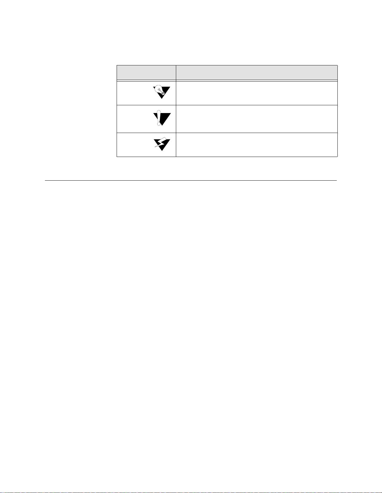
Convention
Description
A
calls attention to important features or instructions.
A
alerts you to serious risk of data loss or other
results that may cause you or the unit trouble if the warning
is not heeded.
A
alerts you to the risk of serious damage to the
unit or injury and possible death to the end user.
Notice
Caution
Warning
Customer Service and Technical Support
Support from Your Network Supplier
•
•
•
Support from Verilink
Telephone
•
•
x WANsuite 5650
Page 11

If these toll-free numbers are not supported in your dialing area, you may call
Verilink by direct dialing 1-256-327-2001.
You can request sales and marketing information or pose a technical support
question about your Verilink product by contacting us at the e-mail addresses
provided below. Verilink will respond to e-mailed requests for support during
regular business hours (8
A.M
.
–5 P.M.
CST, Monday–Friday) .
Sales and Marketing: info@verilink.com
Technical Support: support@verilink.com
Access the lat est networki ng informati on on Veril ink’s Internet Web site by
entering our URL into your Internet browser:
http://www.verilink.com/
This service features information about Verilink products, customer service,
technical support, latest news releases, and more.
If for any reason the Buyer must return a Verilink product, it must be returned
to the factor y, shipping prepaid, and pac kage d to the be st comm ercial s tanda rd
for electronic equipment. Verilink will pay shipping charges for delivery on
return. The Buyer is responsible for mode and cost of shipm ent to Verilink.
The Buyer mus t have a Retu rn Mate rial Aut horiza tion (RMA ) numbe r marked
on the shipping package. Products sent to Verilink without RMA numbers will
be returned to the sender, unopened, at the sender's expense.
A product sen t directly to Verilink for r epair must fi rst be assigne d a Return
Material Authorization (RMA) number. The Buyer may obtain an RMA
number by calling the Verilink Customer Service Center at 1.800.926.0085,
extension 2282 or 2322. When calling Verilink for an RMA, the Buyer
should have the following information available:
Model number and serial number for each unit
Reason for return and sympto ms of problem
Purchase order number
Name and phone number of person to contact if Verilink has questions
about the unit(s).
A return address will be provided at the time the RMA number is issued. The
standard delivery method for return shipments is Standard Ground for
domestic returns and International Economy for international returns (unless
otherwise specified).
•
•
Internet
Returning a Unit to Verilink
•
•
•
•
Preface xi
Page 12

xii WANsuite 5650
Page 13

C
HAPTE
R
1
C
Verilink’s
WANsuite 5650
High Speed Network Interface –
BOUT THE
1
A
HAPTER
Introduction
The telecommunications network service m arket is rapidly changing, where
network monitoring, control, and higher performance in packet processing are
not only expected, but demanded, at competitive price points.
is a feature-r ich network t ermination u nit (NTU) for
managing multiple applications and m ixed-mode packet-based services −
including high-speed Internet access − at price points expected of singlefunction devices.
The WANsuite 5650 is a G.shdsl/TDM network termination unit (NTU)
equipped with a network port, an asynchronous supervisory port, a userselectable multi-protocol serial interface, a G.703 port, nine status LEDs, and
four input control buttons.
Features of the WANsuite 5650
Subscriber Line) provides synchronous line rates that will adapt from
2.312 Mbps to 192 kbps. Its spectral compatibility with other DSL services
and extended reach and rate capabilities make G.shdsl the preferable
broadband service delivery mechanism over copper lines for today's service
provider. By extending the addressable market, more end users than ever
before will now be able to obtain true broadband services.
WAN
G.shdsl (Single pair, High-spe ed Digi tal
SUITE
5650
Flexible User Interfaces
The WANsuite 5650 is equipped with two end-user interfaces: a multiprotocol DCE port and a G.703 port. The multi-protocol serial interface can
be easily set by the end user for V.35, V.36, or X.21 to meet your specific
data communications needs. The G.703 port provides you up to 2.048 Mbps
(E1) of bandwidth for your telecommunications equipment. Maximum
About the WANsuite 5650 1-1
Page 14

flexibility or utilization of the SHDSL pipe is achieved by allowing for the
assignment of the individual timeslots to the desired end-user port.
Simple Installation, Management and Troubleshooting
The WANsuite 5650 has been designed for simple installation, management
and troubleshooting. Power and communications interfaces are easily
accessed on the rear panel. The nine tri-color LEDs on the front panel
provide quick and easily recognizable status indications of unit operation.
The WANsuite 5650 supports the full set of standard EOC commands
allowing for remote management of the NTU from the DSLAM/switch. The
local supervisory port can also be utilized for management of the unit in
conjunction with a comprehensive set of VT100 screens. The four input
control buttons on the front panel of the WANsuite 5650 provide a simplified
means of troubleshooting by accessing unit diagnostic loops.
A powerful core architecture
Three data ports: SHDSL, G.703/704, and multi-protocol
x64k
SHDSL WAN interface
Multi-protocol
x64k serial port soft ware-configurable for V.35, V.36 or
X.21
PowerPC™ platform with 8 Mbytes of RAM
G.703 port supports framed and unframed modes
HDB3 and AMI line coding
A suite of performance monitoring tools
Fully supports standard EOC commands
Local management port for on-site management, monitoring and
troubleshooting
Nine LED status indicators
Front panel control buttons to simplify troubleshooting
Programmable alarm thresholds
Features Summary
•
•
•
•
•
•
•
N
N
•
•
•
•
•
•
1-2 WANsuite 5650
Page 15
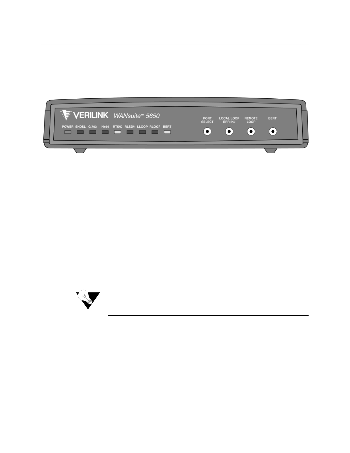
Front Pane l
The front panel of the WANsuite 5650 has four user-activated input control
buttons and nine LED status indicators that provide access to unit diagnostics
loops for the data ports.
The following sections describe the functions of the LED indicators and the
control buttons.
The WANsuite 5650’s front panel control buttons are described in the
following paragraphs.
The WANsuite 5650’s ports are defined as SHDSL, G.703, and (serial)
x64k
port interfaces. The
PORT SELECT
button is used to cycle through and select
from the available ports. When a particular port is selected using the
PORT
SELECT
button, the port’s corresponding LED will flash. The status of the
LLOOP
, and
RLOOP
LEDs will be the summary of the test states for the port
interfaces.
The
PORT SELECT
button cycles through the following port options on each
successive press:
No port selection
Nx64k (serial interface) port
G.703 port
SHDSL port
When the
Nx64k (serial interface)
port is selected, the LED labeled
Nx64
flashes as an indication. The
LOCAL LOOP/ERR INJ
and
REMOTE LOOP
buttons
Figure 1.1
Front Panel Buttons
Port Select Button
Front Panel of WANsuite 5650
N
NOTICE:
When PORT SELECT is set to "No Selection" (as indicated by no
flashing port LEDs), the LLOOP, RLOOP and BERT buttons are
disabled.
•
•
•
•
About the WANsuite 5650 1-3
Page 16

initiate/terminate tests and the corresponding LEDs indicate the status of tests
on this port only.
When on the G.703 port selection, the
G.703
port LED flashes as an
indication. If there is only a single service on the G.703 port then the
LOCAL
LOOP/ERR INJ
and
REMOTE LOOP
buttons initiate/terminate tests and the
corresponding LEDs indicate the status of tests on this port only.
When on the SHDSL port selection, the
SHDSL
port LED flas hes as an
indication. The
LOCAL LOOP/ERR INJ
and
REMOTE LOO P
buttons initiate/
terminate tests and the corresponding LEDs indicate the status of test s on this
port only. These tests are on the aggregate SHDSL payload.
The
REMOTE LO OP
button will invoke a G.SHDSL Network Side Transparent
Loop (see fi gure A.1).
Either the G.703 port or the Serial interface Nx64 will have transparent loop
with the
LOCAL LOO P
button (see figure A.2 or figure A.3).
Default: E nabled.
Default: E nabled.
Default: E nabled.
LED Indicators
The table below describes the WANsuite 5650’s front panel LED indicators.
SHDSL
G.703
Nx64
Nx64
G.703
SHDSL
NOTICE:
PORT SELECT will not operate if any l ocally initiated tests are in
progress.
Local Loop/Error Inject Button
Remote Loop Button
BERT Button
NOTICE:
NOTICE:
NOTICE:
1-4 WANsuite 5650
The
port select button
When no port is selected (indicated by none of the port LEDs flashing),
only the PORT SELECT button is enabled.
When no port is selected, the LL and RL LEDs display a summation of
the test states of the
,
, and
(serial interface),
port LEDs will flash when selected by the
, and
ports.
Page 17

Table 1.1
LED Label
Off
Green
Amber
Red
POWER
No Power
Power applied to unit
Unit in test mode.
SHDSL
Mains Power Off
Trained with good
signal quality
Trained with marginal
signal quality
Training or attempting
to train with poor
signal quality and/or a
major network port
alarm is active
G.703
Service not configured
Service configured and
interface is operating
normally
Service is configured
and has minor alarms:
RAI; Slip
Service configured and
interface is not
operating normally:
LOS; LOA; AIS.
Nx64
Service not configured
Service configured and
interface is operating
normally
Service configured and
interface is not
operating normally or
port mismatch
RTS/C
Nx64k service not
configured
RTS/C
control line is OFF
"RTS" or "C" control
line (from DTE) is ON
RLSD/I
Nx64k service not
configured
RLSD/I
control line is OFF
"RLSD" or "I" control
line (from DTE) is ON
LLoop
No loop present
A local loop is active
on the selected
customer port
(button controlled)
A local loop is active on
the selected customer
port
A local loop is active
on the SHDSL port
RLoop
No loop present
A remote loop is active
on the selected
customer port
(button controlled)
A remote loop is active
on the selected
customer port
A remote loop is active
on the SHDSL port
BERT
not applicable
not applicable
not applicable
not applicable
LED Indicators
or
or
About the WANsuite 5650 1-5
Page 18
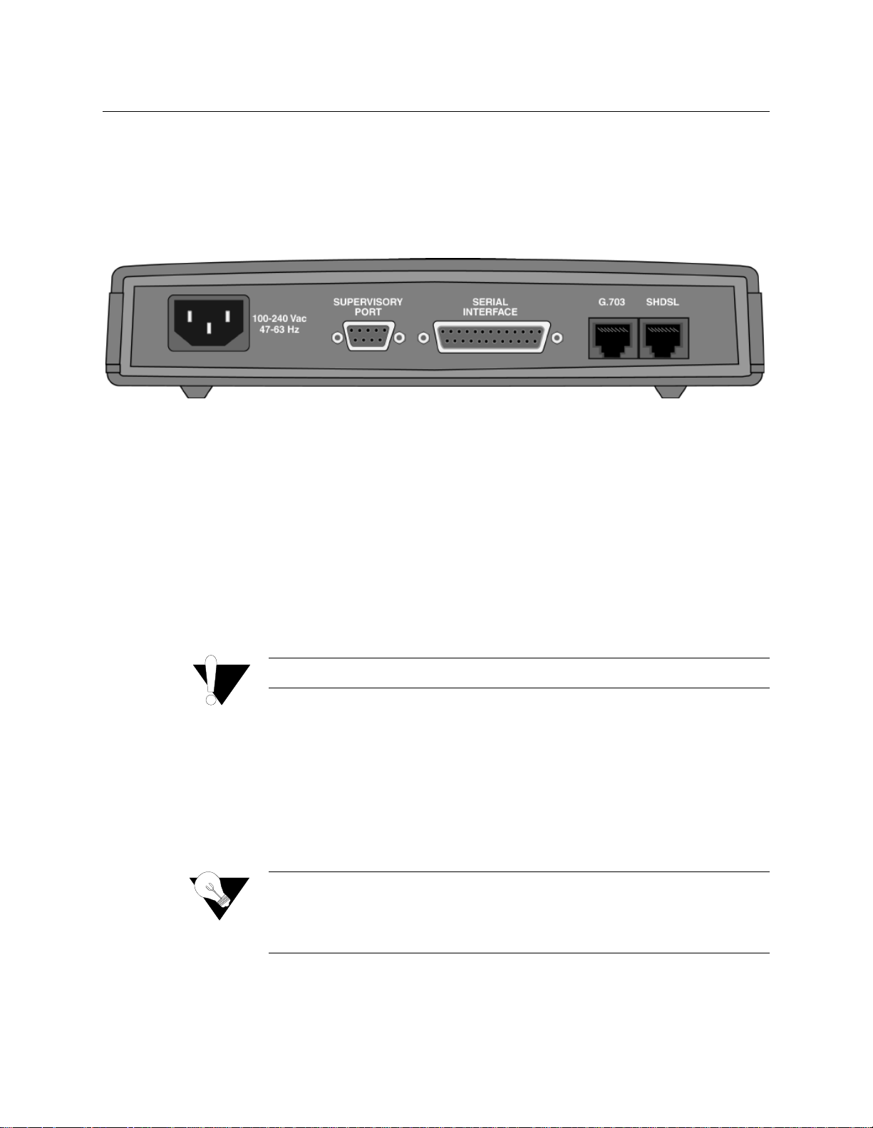
Rear Panel Connections
The rear panel of the WANsuite 5650 has five connectors. From left to right
(as shown in Figure 1.2 below) these connectors are the power port,
supervisory port, serial interface (Nx64k), G.703 port, and SHDSL port. The
connectors are described in detail in the following paragraphs.
The
POWER
port
is a standard grounded three-prong connector. This 100-240
VAC power receptacle is rated at 47–63 Hz. To apply power to the unit,
simply plug the supplied power cord into the unit’s
POWER
port and then
connect the wall plug to an appropriate electrical outlet. The unit has no
power switch.
When power is applied to the unit, the front panel indicators flash for
approximately 10 to 15 seconds as the unit initializes. The green
POWER
LED on the front panel will remain illuminated as long as the unit receives
power. This LED turns amber when the unit is in test mode.
If the
POWER
indicator does not illuminate, check the power connections and
the primary A C circuit brea ker.
The WANsuite 5650 provides nonvolatile memory retention of the unit
configuration in case of a power failure. This feature allows the unit to
automatically restore normal service following a power loss.
Figure 1.2
Power Connection
WANsuite 5650 Rear Panel
1-6 WANsuite 5650
CAUTION:
Always connect the power cord to a grounded electrical outlet.
Power Failure
NOTICE:
Because the WANsuite 5650 does not employ an internal battery or time
chip, the unit will not retain time and date information in the event of a
power failure. The unit marks time beginning at 00:00 with each power
cycle.
Page 19

Supervisory Port
The
SUPERVISORY P ORT
is a DB-9 female DCE connector configured for 8
bits, no parity, and 1 stop bit. Bit rates are configured through the unit’s
VT100 interface. The Supervisory port speed can be set to 1200, 2400, 4800,
9600, 19200, 38400, 57600, or 115200 bps. The initial default rate of the
Supervisory port is 38400 bps.
On power-up, the Supervisory port sends out diagnostic messages at the bit
rate of 115.2 kbps until the supervisory service acquires the Supervisory port,
after which the port speed is changed to the setting in the Supervisory
interface screen.
The
SERIAL INTERFACE
located on the rear of the WANsuite 5650 is a multi-
protocol interface presented physically as a DB-25 connection. The protocols
supported by this inte rface are V.35, V.36, and X.21.
Cables that adapt the DB-25 interface to the 34-pin V.35 interface are
available. These cables are optional equipment and their part numbers are
listed in
on page A-6. DB-25-to-DB-25 cables are also
available if your installation requires them. Refer to
on
page A-6 for details. Pin assignments for the serial interface are also listed in
Appendix A, "
.
FC C rule s requ ire tha t interco nn ectin g ca bles ca rryin g high -spe ed d ata
be appropriately shielded to minimize radio frequency interference.
The
G.703
port connection on the rear panel of the WANsuite 5650 is a
standard eight- pin modular jack with a receive signal level of -27 dB that
terminates a s 120 ohms. To view the pinout assignments for these interf aces,
refer to
on page A-8.
The
SHDSL
port connection on the rear panel of the WANsuite 5650 is a
standard eight- pin modular jack with a receive signal level of -24 dB that
terminates a s 135 ohms. To view the pinout assignments for this interfa ce,
refer to
on page A-8.
Serial Interface
G.703 Port
NOTICE:
Ordering Information
CAUTION:
For information on pinout assignments for this con nector, refer to
"Supervisory Port Pin Assignments" on page A-8. See "Ordering
Information" on page A-6 for information on cables for this connector.
Ordering Information
Specifications"
G.703 Connector Pin Assignments
SHDSL Port
SHDSL Interface Pin Assignments
About the WANsuite 5650 1-7
Page 20

1-8 WANsuite 5650
Page 21

C
HAPTE
R
2
This chapter describes the contents of your WANsuite 5650 shipment and
provides information on connecting and installing the unit.
Unpacking and Inspection
The WANsuite 5650 is shipped in cardboard cartons with foam inserts for
shock and vibration protection. When your shipment arrives, inspect the
shipping container and contents, and compare all items w ith those on the
packing list.
If the contents of the shipment are incomplete or if there is mechanical
damage or defect, notify Verilink. (Refer to
If the ship ping conta iner or c ushioning material is damage d, notify the carrie r
and Verilink immediately and make a notation on the delivery receipt that the
container was damaged. (If possible, obtain the signature and name of the
person making delivery.) Retain the packaging material until the contents of
the shipment have been checked for completeness and the unit has been
checked both mechanical ly and electric ally.
NSTALLATION
C
2
I
HAPTER
Support from Verilink
on page x.)
Supplied Materials
The WANs uite 5650 ship s with the follow ing standard items:
•
WANsuite 5650 unit
•
Power cable
•
Network cable
•
Supervisory cable
•
End user documentation
For specific applications, see Appendix A,
and adapters. For further assistance, contact Verilink Technical Support (800285-2755 or 256-327-2255).
Specifications
, for additional cables
Installation 2-1
Page 22

2-2 WANsuite 5650
Page 23

C
HAPTE
R
3
Introduction
This chapter describes the menus and options associated with the WANsuite
5650’s VT100 interface. The screens displayed throughout this chapter were
accessed through the Supervisory port.
Accessing the VT100 Interface
You can access the VT100 inte rface locally via the Supervisory port. To
access the VT 100 screens, verify that the Supervisory type is “tty” a nd that
the Supervisory port speed is set to 38400 bps (the unit’s default port speed).
Screen Components
The VT100 terminal screens have several components common to all screens
(see Figure 3.1 below). These components include the device type (Verilink
WANsuite 5650), which is centered on the screen, the software and hardware
revision nu mbe rs (up per left ), th e ti me ( uppe r rig ht), the menu tit le ( “Main ” in
the figure below), and the serial number under which the unit is operating.
C
3
VT100 I
HAPTER
NTERFACE
Figure 3.1
NOTICE:
VT100 Terminal Screen Components
Because the WANsuite 5650 does not employ an internal time chip, the
unit cannot display the actual time of day. Rather, the “Time”
displayed on-screen represents the amount of time that the unit has been
operating since its last power cycle or reset. The unit marks time
beginning at 00:00 with each power cycle.
VT100 Interface 3-1
Page 24

Cursor Controls
The VT100 interface uses a blinking cursor to select various menus and then
to select sub-menus and/or fields w ithin those menus. You can navigate using
this cursor in different ways, depending on the program you use. Most
programs allow use of the “Tab” key; others allow use of the arrow keys.
For keyboards that don’t have these standard keys or have only some of them,
an alternative set of cursor control commands is provided. Perform each
command by pressing a letter key while holding down the “Ctrl” key. You
may use the alternative commands (listed in the table below) and keyboard
commands interchangeably at your discretion.
You can navigate further within a menu as descri bed below.
Each menu screen is composed of fields. The two basi c field types are user-
selectable (most of these are in brackets or parentheses) and display-only (no
brackets or parentheses). If you can move the highlighted cursor to a field,
that field is user-selectable; all other fields are display-only. User-selectable
fields are those in which you can make changes or execute commands. To
save changed parameters, in most cases you will “Esc” out of the current
menu after cha nging th e paramet ers. In som e cases, you will pres s the “Ent er”
key to save new parameters.
Fields enclosed in brackets [ ] offer a list of selections from which to choose.
The selections may be made by pressing your Spacebar to “toggle” between
choices. Each time the Spacebar is pressed, a new item appears. When the
item you wish to choose is displayed, press the “Esc” key to save it.
Fields enclosed in parentheses ( ) are manipulated by one of two methods.
The first method is to press the “Enter” key to simply execute the defined
function. The second m ethod requires typing input. The most common type
of field in parentheses accepts typed input in the form of letters and/or
numbers. Typing characters when the field is highlighted causes the current
Keyboard Command
Alternate Command
Left Arrow
Ctrl+S
Right Arrow
Ctrl+D
Up Arrow
Ctrl+E
Down Arrow
Ctrl+X
Backspace
Ctrl+H
Delete
Ctrl+Z
NOTICE:
If you are not able to use your arrow keys, you may need to change the
settings within your terminal emulation program.
Field Types
3-2 WANsuite 5650
Page 25

entry to be replaced by the new characters. To edit an existing entry rather
than replace it, press the right arrow key to move the cursor to the point that
needs editing. You may insert characters or delete them. Typed data must
always be inserted rather than typed over. If the field is full, you must first
delete at least one character before you can add another.
Table (column) headings enclosed with braces < > indicate that any entry in
that column is selectable. (See Figure 3.7
on page 3-10 for an example.)
NOTICE:
The Main Menu screen (shown in Figure 3.2) lists the functional user-
accessible menus. To activate a specific menu, tab to it (or use your arrow
keys) and press “Enter.” To exit this or any subsequent menu, press the “Esc”
key. If you exit the Main menu, th e terminal interf ace program ter minates.
This is a valid way to end a session. When you exit any menu other than the
Main menu, you will be returned to the previous screen.
The VT100 screens are automatically refreshed every 5 seconds.
However, you may also press Ctrl+U to refresh data on any screen.
Main Menu and Menu Structure
Figure 3.2
VT100 Main Menu Screen
CAUTION:
If you do not enter a keystroke for 10 minutes, the terminal interface
logs off automatically.
VT100 Interface 3-3
Page 26

System Screen
The first option on the Main menu screen is the System screen (Figure 3.3).
This screen lets you view and set specific information about the unit in
service.
The System screen displays the fields shown in the table below.
The System screen displays the user-selectable prom pts listed in the table
below and described in detail in the paragraphs that follow.
Field
Description
Contact
Read/write field used to store the name of a point-of-contact for
system failu re.
Name
Read/write field that holds the unit’s name.
Location
Read/write field that holds the unit's location.
New Password
Read/write field used to change the unit’ s passw ord. Acceptable
characters for use in a password are digits 0–9 and letters A–Z
and a–z, for a total of 62 distinct characters.
Prompt
Function
Download App Code
Initiates the downloading of new application code.
Save and Restart
Saves the current configuration and restarts.
Maintenance Reset --
TDM
Resets unit to its default TDM configuration.
Figure 3.3
System Screen
3-4 WANsuite 5650
Page 27

Download App Code
Use the “Download App Code” field to upgrade the software in your
WANsuite 5650 unit. The revision level for the software your unit is currently
using is displayed in the top line of the VT100 screens. After installing a
software upgrade, the new revision level will be displayed on this line.
To reprogram your WANsuite 5650 unit with new software:
Select the “
” field and press the “Enter” key. A
confirmation screen similar to the one shown in Figure 3.4 will display.
Select “
” to continue with the procedure. The screen will clear and the
message “
” will appear at the bottom.
After a short amoun t of time, the scree n will di splay the messages “
”
and “
.” At this point the software upgrade file must be
transferred to the unit.
A series of “
’s” will be displayed at the bottom of the screen while the
system waits for the file to begin downloading. Once it has begun, the
entire download process may take several minutes.
Set your teminal emulation program’s Protocol selection to “1K Xmodem.”
Use your terminal emulation program to select the a ppropriate
file for
uprading the software and begin sending the file. (If using HyperTerminal,
choose “Transfer/Send File...”.)
At the completion of the download, your system’s screen should display:
The unit will now update the application program flash, during which the
BERT LED will flash on and off. Once the flash has been updated, the unit
will reboot. After the unit reboots you should see the new software revision
level displayed in the top line of the VT100 screens.
Select this prompt to perform a Maintenance Reset to the unit’s default TDM
configuration. Any existing configurat ions will be lost and the unit will be set
back to its factory defaults. Selecting the Maintenance Reset prompt will
display a confirmation screen (Figure 3.4) where you will choose either to
proceed with the maintenance reset or abandon the procedure.
CAUTION:
1
2
Do not allow power to be removed from the unit while its memory is
being reprogrammed.
Download App Code
Yes
FILLING MEMORY WITH FFF
3
START UPLOAD
4
C
5
6
7
FILLED
Maintenance Reset--TDM
VT100 Interface 3-5
Page 28

Figure 3.4
Selecting “Save and Restart” will display a confirmation menu similar to that
shown in Figure 3.4. Select “YES” to save the current configuration settings
and then restart the unit, or select “NO” to abandon the procedure.
Confirmation Screen
Save and Restart
NOTICE:
Performing a “Maintenance Reset” or a “Save and Restart” will
terminate communications with the unit. Refresh (by pressing
“Ctrl+U”) after approximately 10 seconds to restore communications .
3-6 WANsuite 5650
Page 29

Interfaces Screen
The Interfaces screen displays a list of all the unit’s available interfaces as
shown in Figure 3.5.
From the Interfaces screen, you may choose from the following: SHDSL,
G.703, Serial, or Supervisory. Selecting an interface will display an initial
configuration screen for that interface. Each of these interfaces is described
below.
The SHDSL screen (Figure 3.6) lets you view and make changes to the
SHDSL interface's configuration as described below. In addition, this screen
displays the activity status and alarm values for the SHDSL interface.
Figure 3.5
Interfaces Screen
SHDSL Screen
VT100 Interface 3-7
Page 30

Figure 3.6
Unit Type
Selects the unit type. T U-R repre sents a CP E termina l unit; TU- C represen ts a
CO terminal unit. The TU-C mode is for back-to-back operation needed for
E1 replac ement ap plication s.
Values:
TU-R, TU-C
Default:
TU-R
Timing (T x/Rx)
Sets the transmit and receive timing source to synchronize the unit’s internal
timing gener ators. In all cas es, slips are co ntrolled to oc cur on frame
boundaries at the network port when timing synchronization is lost. Choices
are as follows:
Internal –
The unit’s internal frequency standard is used for all timing.
SHDSL –
Timing is derived from the network recovered clock. Most
applications use this selection. (Default)
Serial –
The Transmit clock is sourced from the Nx64k and the Receive clock
is the SHDSL port recovered clock.
G.703 –
The Transmit clock is sourced from G.703 and the Receive clock is
the SHDSL por t recovered clock.
Valid Timing options depend on the selected unit type:
For STU-C:
Values:
Internal/Internal, G.703/G.703, Serial/Serial
Default:
Internal/Inter nal
For STU-R:
Values:
SHDSL/SHDSL
Default:
SHDSL/SHDSL
SHDSL Screen
3-8 WANsuite 5650
Page 31

Expected R epeaters
This field is used to provision the number of repeaters in the selected span.
Values:
0, 1, 2, 3, 4, 5, 6, 7, 8
Default:
0 (zero)
Span Configuration
This value in this field represents a span configuration profile in the Span
Configurat ion Profile Table, which a pplies to this sp an. By defaul t, this
object will have the value “DEFVAL” (the index of the default profile).
Values:
User Span Profile 1, User Span Profile 2, DEFVAL (Default
Value)
Default:
DEFVAL
Span Alarm
Configuration
This value in this field represents an Alarm configuration profile in the
Endpoint Alarm Configuration Profile Table. The alarm threshold
configuration in the referenced profile will be used by default for all segment
endpoints in this span. Individual endpoints may override this profile by
explicitly specifying some other profile in the table. By default, this object
will have the value 'DEFVAL' (the index of the default profile).
Values:
User Alarm Profile 1, User Alarm Profile 2, User Alarm
Profile 3, DEFVAL (Default Value)
Default:
DEFVAL
The following paragraphs describe the display-only fields of the SHDSL
configuration screen.
Status
Provides overall st atus information of the span.
Detail Status
Displays current activity status of the network.
EOC In
Displays the EOC (Embedded Operations Channel) In.
EOC Out
Displays the EOC (Embedded Operations Channel) Out.
Discovered Repeaters
Displays the number of discovered repeaters on this span.
Line Rate
Displays the actual negoti ated line rate .
Maximum Line Rate
Displays the maximum physical line rate.
Transmission Mode
Displays the actual transmission mode (Annex-A or Annex-B).
In addition to the user-configurable and display-only fields, the SHDSL
screen has four function fields that lead to additional configuration screens.
These fields are Channels, Configuration Profiles, Alarm Profiles, and Span
Endpoints. To access these screens, simply move the cursor to one of these
fields and press the “Enter” key.
Selecting the “Channels” option from the SHDSL screen will display a TDM
Service Details screen. This screen is described in detail on page 3-30.
VT100 Interface 3-9
Page 32

Configuration Profiles Screen
Selecting the Configuration Profiles function field from the SHDSL screen
will displa y the followin g screen:
This screen is used to view the available SHDSL span configuration profiles
(by profile name) and their established parameters. Each of the three
available configuration profiles
represents a span configuration profile in the
Span Configuration Profile Table, which applies to this span
.
Displayed parameters for each span configuration profile include the
following:
Configuration N am e
Displays the name of the defined span configuration profile.
Rate (Min)
Displays the minimum attai nable line rate in the span.
Rate (Max)
Displays the maximum attain able line rate in the span.
Remote
Shows whether the option to span remote is enabled or disabled.
Power Feeding
Shows whether support for optional power feeding in a SHDSL line is
enabled or disabled.
The user may view and change the details for a configuration profile by
moving the cursor to the desired profile name and pressing the “Enter” key.
(A Configuration Details screen like the one in Figure 3.8 will be displayed.)
The Configuration Details screen (
Figure 3.8
) is accessed by selecting a
profile name from the Configuration Profiles screen and pressing the “Enter”
key.
Figure 3.7
Configuration Profiles Screen
Configuration Details Screen
3-10 WANsuite 5650
Page 33

Figure 3.8
This screen allows the user to view and change various parameters of the
selected Configuration Profile, which include the following:
Wire Mode
Displays the type of wire interface used by the span (always Two-Wire).
PSD Type
Used to confi gure the use of s ymmetric/a symmetric P SD (Power Spe ctral
Density) ma sk for the assoc iated line.
Values:
Symmetric, Asymmetr ic
Default:
Symmetric
Data Rate (M in)
This field is us ed to set the min imum attainab le line rate in the span.
D ata R a te (Max )
This field is us ed to set the maxi mum attainab le line rate in th e span.
Remote
This field enables/disables support for remote management of the units in a
SHDSL line from the STU-R vi a the EOC.
Values:
Enabled, Disabled
Default:
Enabled
Power Feeding
This field ena bles/disab les support fo r optional pow er feeding in a SHDSL
line; however, this version of the WANsuite 5650 supports only wetting
current. Other values will have no effect.
Values:
No Power, Power Feeding, Wetting Current
Default:
No Power
Transmission Mode
Used to set the regional setting of the span.
Values:
Annex-A
, Annex-B
Default:
Annex-B
Configuration Details Screen
(ITU-T G.991.2)
(ITU-T G.991.2)
VT100 Interface 3-11
Page 34

Alarm Profiles Screen
Selecting the “Alarm Prof iles” option on the SHDSL scr een will displa y the
following screen:
The Alarm Profiles screen displays the current status of endpoint alarms.
Information is displayed for the following alarm parameters:
Alarm Profile N am e
This field displays the unique index associated with this Endpoint Alarm
profile. The values are obtained from the alarm configuration profile
referenced by this objec t.
Loop A tten
This field indicates the loop attenuation threshold
SNR M argin
This field indicates the SNR margin threshold.
ES
This field indicates the errored seconds threshold.
SES
This field indicates the severely errored seconds threshold.
CRC
This field indicates the CRC anomalies threshold.
LOSWS
This field indicates the LOSW second threshold.
UAS
This field indicates the unavailable seconds threshold.
The parameters for each Alarm Profile can be changed by moving the cursor
to the desired Profile name and pressing the “Enter” key; this will display an
Alarm Profil e Details scre en (Figure 3.10 ) for the selecte d profile. The
available configuration parameters are described below.
Figure 3.9
Alarm Profiles Screen
3-12 WANsuite 5650
Page 35

Alarm Profile Details Screen
The Alarm Profile Details screen (Figure 3.10) is accessed by moving the
cursor over a profile name in the Configuration Profiles screen and pressing
the “Enter” key. This screen is used to configure the alarm threshold values
to be used for the selected segment endpoint.
P ro file N a me
This field displays the unique index associated with this Alarm profile.
Loop Attenuation
This field configures the loop attenuation alarm threshold. When the current
value exceeds this threshold, a crossing trap will be generated.
SNR M argin
This field configures the SNR margin alarm threshold. When the current
value drops below this threshold, a crossing trap will be generated.
ES
This field configures the threshold for the number of errored seconds (ES)
within any given 15-minute performance data collection interval. If the value
of errored seconds in a particular 15-minute collection interval reaches/
exceeds this value, a tr ap will b e generat ed. One tr ap will be sent per interval
per endpoint.
SES
This field configu res the th reshol d for the number o f seve rely err ored sec onds
(SES) within any given 15-minute performance data collection interval. If the
value of severely errored seconds in a particular 15-minute collection interval
reaches/exceeds this value, a trap will be generated. One trap will be sent per
interval per endpoint.
CRC
This field configur es the threshold for the number of CRC anomalies within
any given 15-minute performance data collection interval. If the value of
CRC anomalies in a particular 15-minute collection interval reaches/exceeds
this value, a tr ap will be genera ted. One trap wi ll be sent per inte rval per
endpoint.
Figure 3.10
Alarm Profile Details Screen
VT100 Interface 3-13
Page 36

LOSWS
This field configur es the threshold for the number of Loss of Sync Word
(LOSW) Seconds within any given 15-minute performance data collection
interval. If the value of LO SW in a partic ular 15-mi nute collec tion interva l
reaches/exceeds this value, a trap will be generated. One trap will be sent per
interval per endpoint.
UAS
This field configur es the threshold for the number of unavailable seconds
(UAS) within any given 15-minute performance data collection interval. If
the value of UAS in a particular 15-minute collection interval reaches/exceeds
this value, a tr ap will be genera ted. One trap wi ll be sent per inte rval per
endpoint.
Span Endpoints Scree n
Selecting the “Span Endpoints” field on the SHDSL screen will display the
screen seen in Figure 3.11. The Span Endpoints screen displays each unit of
the span. User-selectable prompts are provided to view the Span Endpoint
Details (page 3-14), Span Endpoint Maintenance (page 3-16), Alarm Profiles
(page 3-12), and Span Endpoint Performance (page 3-17) screens. If the
SHDSL link is not up, only the local side of the span will be displayed.
Moving the cursor to an entry in the Unit column of this screen and pressing
the “Enter” key will display the span endpoint details for that unit. (See
on page 3-14.)
The Span Endpoint Detail s screen (Figure 3.12) is accessed by moving the
cursor to a Unit identifier in the Span Endpoints screen and pressing the
“Enter” key. This screen supports retrieval of unit inventory information
available v ia the EOC from units in a SHDS L line.
Endpoint Details Screen
Span
Figure 3.11
Span Endpoints Screen
Span Endpoint Details Screen
3-14 WANsuite 5650
Page 37

Figure 3.12
This screen provides details on the following span endpoint parameters:
Ve n dor ID
Displays the Vendor ID.
Model Number
Displays the Vendor model number.
Serial Num ber
Displays the Vendor serial number.
EOC Software Version
Displays the Vendor EOC version.
Standard Version
Displays the version of the SHDSL standard implemented.
List Num ber
Displays the Vendor list number.
Issue N u m b er
Displays the Vendor issue number.
Software Version
Displays the Vendor software version.
Equipment Code
Displays the equipment code conforming to ANSI T1.213, Coded
Identifica tion of Equipm ent Entities.
Transmission Mode
C a p a b ility
Displays the transmissi on mode capabi lity of the SH DSL unit.
Endpoint Side
The endpoint side will always be “Network” when unit type is TU-R.
Wire Pair
Wire pair will always be “Wire Pair 1.”
Vendor Other
Displays other vendor information. For a WANsuite 5650 unit, this field
displays hardware revision (2 digits), manufacturing date (6 digits) and
software checksum (4 digits).
In addition to the displayed endpoint details, this screen also provides function
fields that are used to access the Span Endpoint Maintenance screen (Figure
Span Endpoint Details Screen
VT100 Interface 3-15
Page 38

3.13), Span Endpoint Performance Screen(s) (Figure 3.14), and the Alarm
Profiles screen (Figure 3.9).
Span Endpoint Maintenance Screen
The Span Endpoint Maint enance sc reen (Fi gure 3.13 ) is ac cessed by mov ing the
cursor to the “Maintenance” field in the Span Endpoint Details screen and
pressing the “Enter” key. This screen supports maintenance operations (e .g.,
loopbacks) to be performed on segment endpoints.
The Span Endpoint Maintenance parameters are described as follows:
Loopback Type
This field controls configuration of loopbacks for the associated segment
endpoint.
Values:
No Loopback, Normal Loopback, Special Loopback
Default:
No Loopback
Loopback Tim eout
This field configures the timeout value in minutes for loopbacks initiated at
segments endpoints contained in the associated unit. A value of 0 (zero)
disables the timeout.
Tip Ring
This field indicates the state of the tip/ring pair at the associated segment
endpoint.
Pow er B ack off
This field configures the receiver at the associated segment endpoint to
operate in default or enhanced power backoff mode.
Values:
Default, Enhanced
Default:
Default
Figure 3.13
Span Endpoint Maintenance Screen
NOTICE:
3-16 WANsuite 5650
Only the Normal Loopback option has been implemented for the
WANsuite 5650.
Page 39

Power Source
This field indicates the DC power source being used by the associated unit.
Restart Endp oint
This field enables the manager to trigger a soft restart of the SHDSL line at
the associated segment endpoint. The manager may only set this object to the
“restart” value to i nitiate a restart. The agen t will pe rform a restart af ter
approximately 5 seconds, and restore the object to the “ready” state.
Values:
Ready, Restart
Default:
Ready
Span Endpoint Performance Screen
The Span Endpoint Performance screen (Figure 3.14) is accessed by moving
the cursor to the “Performance” field in the Span Endpoint Details screen and
pressing the “Enter” key. This screen displays information on the
performance and error status of the span endpoints. This information is
provided in a summary form for complete totals as well as that for current 15-
minute and 1-day intervals.
Tim e Elapsed
Total elapsed time (in seconds) in the current 15-minute and 1-day intervals.
ES
Count of Errored Seconds (ES) on this endpoint since the unit was last
restarted.
CRC
Count of CRC anomalies on this endpoint since the unit was last restarted.
LOSWS
Count of Loss of Sync Word (LOSW) Seconds on this endpoint since the unit
was last rest arted.
SES
Count of Severely Errored Seconds (SES) on this endpoint since the unit was
last restarte d.
UAS
Count of Unavailable Seconds (UAS) on this endpoint since the unit was last
restarted.
Figure 3.14
Span Endpoint Performance Screen
VT100 Interface 3-17
Page 40

Also included on the Span Endpoint Performance screen are options to view
the span endpoint performance summaries for 15-minute inte rvals and for 1-
day intervals. These screens display only a summary of the errors (ES, SES,
CRC, LOSWS, UAS) that have occurred on the span during the interval
selected.
The 1-Day Intervals screen also includes the status of monitored seconds
(MoniSec), which is defined as the amount of time in a one-day interval over
which the monitoring information is actually counted. This value will be the
same as the int erval durati on except in si tuations whe re, for any reas on,
performance monitoring data could not be collected.
The 15-Minute Intervals table provides one row for each endpoint
performance data collection 15-minute interval. The 1-Day Intervals screen
provides one row for each endpoint performance data collection 24-hour
interval.
G.703 Screen
The G.703 Configuration screen (Figure 3.15)
lets you view and make
changes to the G.703 interface's configuration as described below. In addition,
this screen provides a table that displays the error status values for the G.703
interface.
Line Coding
Sets the G.703 port line coding.
Values:
HDB3, AMI
Default:
HDB3
15-Minute and 1-Day Intervals Screens
Figure 3.15
G.703 Screen
3-18 WANsuite 5650
Page 41

CRC4 Mode
Used to disable or enable CRC-4 detection/generation towards the SHDSL
network. When less than 32 timeslots are configured on the G.703 port, CRC-
4 detection/generation is based on filling the unused timeslots with a fixed
pattern configurable via the management interface. This CRC-4 detection/
generation is also require d for multirat e (single or sim ultaneous serv ices)
where less than 31 G.704 timeslots are carried over the SHDSL line.
Values:
Disable, Enable
Default:
Disable
Frame Type
Sets the type of framing used by the G.703 port.
Values:
Framed, Unframed
Default:
Framed
E Bit Generation
In framed mode,this is used to configure the CRC-4 detection/generation via
the manage ment inte rface.
Values:
Disable, Enable
Default:
Disable
RAI Generation
The RAI (Rem ote Alarm In dication) det ection shal l be in accordan ce with
ITU-T I.431 sec 3.4.1.2 and ITU-T G.704 Table 5A.
Values:
Disable, Enable
Default:
Enable
Sa4, Sa5, Sa6, Sa7, Sa8
Displays the status of special spare bits found in Timeslot 0.
Error Status and Alarm Thresholds Table
The unit can be programmed to generate an alarm condition based on a
specific level of performance degradation. The G.703 screen presents a table
that provides current error status and alarm threshold information.
Acceptable alarm thresholds are set for periods of 15 minutes (900 seconds).
The error types listed in the following paragraphs can be preset to a value
between 0 and 900 seconds. Setting a threshold field to “0” (zero) disables the
alarm on that statis tic. To effectively disa ble al arm rep ortin g, set all thres holds
to “0” (zero).
The 15-minute time fram e is a time window based on the accumulated counts
over the previous 15 one-minute intervals. In all cases, if the number of actual
network errored seconds in the previous 15 minutes reaches the preset
threshold for the specified error type, an alarm condition is declar ed.
The four columns of the status table are as follows:
•
Status
: Displays the current status of the network port.
Alarm
: Displays the alarm value of the network port. The unit declares an
alarm as soon as the count exceeds the threshold set.
Count
: Displays the number of events or occurrences of this statistic that
have been detected.
Threshold
: Displays a read/write field that can be set to a desirable
threshold.
•
•
•
VT100 Interface 3-19
Page 42

3-20 WANsuite 5650
The table prov ides error st atus and alarm threshold in formation fo r the
following e rror para meters:
ES
Sets the Errored Seconds (ES) threshold. An ES is a 1-second period in which
at least one logic error occurred. The default threshold is 45 seconds.
SES
Sets the Severely Errored Seconds (SES) threshold. An SES is a 1-second
period in which at least 320 CRC errors or one Out- of-Frame (OOF) error
occurred. The default threshold is 5 seconds.
LOSS
Sets the Loss of Signal Seconds (LOSS) threshold. A LOSS is 1-second
period in which the E1 received signal is interrupted. The default threshold is
5 seconds.
UAS
Sets the Unavailable Seconds (UAS) threshold. A UAS is a 1-second period
in which consecutive severely errored seconds cause an unavailable state. The
threshold is 0 (zero) seconds (Disabled).
CSS
Sets the Controlled Slip Seconds (CSS) threshold. The default threshold is 0
(zero) seconds (Disabled).
BPVS
Sets the Bipolar Violation Errored Seconds (BPVS) threshold. A BPVS is a 1-
second period in which at least one bipolar violation occurred. The default
threshold is 0 (zero) seconds (Disabled).
OOFS
Sets the Out of Frame Seconds (OOFS) threshold. An OOFS is a 1-second
period in which a frame sync loss occurred. The default threshold is 5
seconds.
AISS
Sets the Alarm Indication Signal Seconds (AISS) threshold. An AIS is a 1-
second period when unframed all ones are received. The default threshold is 0
(zero) seconds (Disabled).
RAS
Sets the Remote Alarm Seconds (RAS) threshold. An RAS is generated by
the terminal equipment when an improper signal is received from the facility
(or upon receipt of unframed all ones). The default threshold is 0 (zero)
seconds (Disabled).
Reset Tim er
The status table also provides an option for setting the Reset Timer threshold.
This field is the contiguous number of seconds that an alarm parameter must
be clear before the alarm is reset. Applicable values range from 000 through
900. A value of “000” means the alarm will never be reset. The default value
is 30 seconds.
Page 43

The G.703 configuration screen provides the user-selectable prompts
described i n the ta ble below.
Performance
The Performance prompt near the bottom of the G.703 configuration screen
displays a 24-hour performance summary screen (Figure 3.16), which
provides a summary of the error events that have occurred on the G.703
interface during each interval of the past 24 hours.
CAUTION:
To view a screen showing performance details for only a given 15-minute
period in the current 24-hour statistics, use the cursor to highlight the desired
period (Summary, Current, or Interval
) and press the “Enter” key. A screen
like the one below (Figure 3.17) will be displayed.
Prompt
Function
Clear Alarms
Resets the alarm conditions and counts to zero.
Performance
Displays a current count of the number of error events that have
occurred over the past 24 hours.
Channels
Displays the TDM Service Details screen (Figure 3.24
on
page 3-30), show in g e ach chan ne l by in dex num be r . Ea ch
channel’s service (by number) is displayed and can be changed
through user input.
Performance data will be lost upon power cycle or after performing a
Maintenance Reset/Restart.
Figure 3.16
G.703 Performance 24-Hour Screen
x
VT100 Interface 3-21
Page 44

Figure 3.17
Select the “Performance 30 Day” prompt from the G.703 Performance 24
Hour screen to see a detailed summary of the error events that have occurred
during each interval of the past 30 days (shown below in Figure 3.18).
To view a screen showing performance details for only a given 24-hour period
in the current 30-day statistics, use the cursor to highligh the desired period
(Summary, Current, or Interval
) and press the “Enter” key. A screen like
the one below (Figure 3.19) will be displayed.
G.703 Performance 24-Hour Details Screen
Figure 3.18
G.703 Performance 30 Day Screen
x
3-22 WANsuite 5650
Page 45

Serial Screen
The Serial screens let you view and make changes to the unit’s Serial
interface configurations as described in the paragraphs below. To make
changes to any Serial parameter, simply set the parameter to the desired
selection and press the “Esc” key.
Figure 3.19
G.703 Performance 30 Day Details Screen
Figure 3.20
Serial Scr een
VT100 Interface 3-23
Page 46

Typ e
This parameter selects the type of interface (based on its electrical signal
characteristics) used by the equipment connected to the Serial port.
Values:
V.35, V.36, X.21
Default:
V.35
NOTICE:
Mode
By default, the Serial port serves as a DCE port in non-Packet modes.
If the Serial port connects to a DTE device (such as a FRAD or a router), the
Mode parameter must be set to “DCE.”
Values:
DCE
B u n d lin g
Selects whether the DTE channel assignment is made as a “Contiguous”
group or as “Alternate” channels. Selecting “Alternate” ensures ones density.
Because the unit allows individual channels to be configured for a service, a
value of “A rbitrary” will be r eturned fo r this p arameter if the cur rent chan nel
allocation is not contiguous or Alternate. The “Arbitrary” value can only be
supplied by the unit – it cannot be set by the user.
Values:
Contiguous, Alternate, Arbitrary
Default:
Contiguous
Start Channel
Selects the sta rting channe l in the 32-chan nel G.703 bi t stream. Starti ng with
the specifie d channe l, the un it automa tically as signs the channels that fol low.
Values:
1 through 32
Default:
1
# of Channels
Specifies t he number of ch annels to be as signed to the D TE.
Values:
0 through 31
Default:
31
Channel Rate
The unit can operate at any data rate that is a multiple of 64 kbps.
Values:
x64K
Inve rt C lock
In DTE Packet mode, this parameter changes the clock edge of the transited
data. The Invert Clock parameter is only available for use in DTE mode.
Values:
Disable, Enable
Default:
Disable
Tx Clock
Selects the clock the unit uses to sample the data transmitted from the DTE.
When set to “Internal,” the data is sampled directly with the transmit data
All multiple protocol cables (V.35, V.36 and X.21) are optional
equipment and must be ordered thro ugh Verilink or de signed to the
appropriate specifications. Refer to Appendix A, "Specifications‚" for
ordering information and cable specifications.
N
NOTICE:
3-24 WANsuite 5650
Start Channel, Number of Channels, and Channel Rate cannot be
changed if Bundling is not also changed from “Arbitrary.”
Page 47

clock that is also supplied to the DTE as Transmit Clock. The “External”
option uses the external clock from the DTE.
Values:
Internal, E xternal
Default:
Internal
LL
The Local Loopback parameter can be set to “Permanent Off” or “DTE
Driven.” S electing “Perman ent Off” me ans no lo cal loop request s will be
accepted via this line. Selecting “DTE Driven” means the line can accept
local loop requests.
Values:
Permanent Off, DTE Driven
Default:
Permanent Off
V54
Selecting “Enable” allows the unit to respond to in-band V.54 loop codes. If
you select “Disable,” the unit ignores these codes.
Values:
Disable, Enable
Default:
Disable
CTS
The Clear To Send parameter can be set to “Permanent On,” “Permanent
Off,” or “DTE Dr iven.” If this parame ter is set to “Pe rmanent On,” th e CTS is
always “o n” no ma tter wha t the sta te of RTS. If set to “Perm anent O ff,” CTS
is always “o ff” no ma tter w hat t he state of RTS. If set t o “DT E Drive n,” C TS
follows RTS. In addition, when RTS and CTS are off, a pattern of all 1’s
(ones) is transmitte d.
Values:
Permanent On
, Permanent Off, DTE Driven
Default:
Permanent On
DSR
Data Set Ready can be set to “Permanent On,” or “Permanent Off.”
Values:
Permanent On
, Permanen t Off
Default:
Permanent On
DCD
The Data Ca rrier Det ect param eter can b e set to “Permane nt On,” “Perman ent
Off,” or “DTE Driven.”
Values:
Permanent On
, Permanent Off, DTE Driven
Default:
Permanent On
RTS
The Request To Send parameter determines the source from which the unit
reads the RTS signal stat us. If set to “DT E Driven,” the unit gets RTS from
the DTE on the Serial interface. If set to “Permanent On,” RTS is always
perceived as “on.”
Values:
DTE Driven, Permanent On
Default:
DTE Driven
RTS/CTS D elay
The Request To Send/Clear To Send parameter determines how long the unit
waits before it changes the level of CTS to match RTS when the CTS
parameter is set to “DTE Driven.”
Values:
0 (zero) ms, 1 (one) ms
Default:
0 ms
VT100 Interface 3-25
Page 48

3-26 WANsuite 5650
DTR Alarm Control
Lets you set DTR Alarm Control parameters.
Values:
Permanent On, DTE Driven
Default:
Permanent On
DTR Alarm Status
Lets you view the curr ent DTR Alarm status.
Page 49

Supervisor y Screen
The Supervisory Configuration screen (Figure 3.21) displays the current speed
of the Superv isory port inte rface. This sc reen is access ed by selecti ng
“Superviso ry” from the Interf aces scr een.
The Supervisory screen lets you view and change the Supervisory port speed
used by PPP and VT100. The Supervisory port only supports asynchronous
character for mats.
Speed
Changes the Supervisory port speed (in bits per second).
Values:
1200, 2400, 4800, 9600, 19200, 38400, 57600, 115200
Default:
38400
Figure 3.21
Supervisory Config Screen
VT100 Interface 3-27
Page 50

Service Table Screen
Selecting the “Services” option from the Main screen will display the Service
Table screen shown below (Figure 3.22). The Service Table screen provides a
view of the unit’s defined services and displays the Interface, Type, and Pair
parameters for each service.
The Service Table screen displays the available services listed by Index
number. From the Service Table screen, you can navigate:
to a Service Details screen (Figure 3.2 3) from the <Index> column;
to an Interface Details screen (Figure 3.24) from the <Interface> column
(when applicable);
or to a Type Details screen from the <Type> column (when applicable).
The prompts displayed on this screen are described in the following table:
Prompt
Function
Index
Opens the Service Details screen (Figure 3.23
on page 3-29).
Interface
Opens the Details screen for the Interface of the currently selected
service.
Type
Opens the Details screen for the Type of the currently selected service.
Figure 3.22
•
•
Service Table Screen
3-28 WANsuite 5650
•
Page 51

Service Details Screen
This screen al lows the user to select and ch ange the serv ice paramete rs listed
below. The new parameters are saved when you press the “Esc” key and
return to the pr evious screen .
Interface
Selecting one of the available options provided in the “Interface” field will set
the interfac e parame ter for t he curren t service.
Typ e
Selecting one of the available options provided in the “Type” field will set the
type paramete r for the current service.
Pair
User-assigne d i nt eg er fie ld th at sp ec if ies w h er e to ro u te the tr af fi c fr om thi s
service. If the s er vi ce is ter min a ted by t he unit , set this va lue to “0 ” (zero ) .
Figure 3.23
Service Details Screen
VT100 Interface 3-29
Page 52

TDM Service Details Screen
Selecting the Channels function field from the SHDSL screen will display the
TDM Service De tails screen (F igure 3.24).
This screen is used to view and set the TDM service parameters. Each
channel (0–31) is listed along with its configured Service number, Pair, and
Idle Pattern. (Use the PageUp or PageDown commands to view channels not
displayed.) The user can change the values for a channel’s Service or Idle
Pattern by navigating to the desired field and entering the appropriate value.
Service
This field is used to provisi on the service number of the selected cha nnel.
Values:
0, 3, 4, 7, 8
Idle Pattern
This field is used to provision the idle pattern of the selected channel. Values
are represented in hex format.
Values:
0 (zero) to FF
Figure 3.24
TDM Service Details Screen
3-30 WANsuite 5650
Page 53

Applications
Accessed from the Main menu, The Applications screens describe diagnostics
and traps for Layer 3 and above that do not map to a specific service or
interface.
The Diagnostics screen (Figure 3.25) provides a table for viewing the current
settings for the test and maintenance functions performed on the available
interfaces . This screen sho ws an upper- level view of al l the interface s so you
can see if any port is under test. You may change Diagnostic parameters on
the Test Details screen (Figure 3.26), which is accessed by selecting the
appropriate interface under the <Description> column. The properties of the
Diagnostics table are described in the paragraphs below.
Descriptio n
Describes the type of interface selected for testing.
Loop Type
Describes the type of loop test (if any) performed on the selected interface.
The Test Details screen (Fi gure 3.26) is used to set the ty pe of test (if an y)
performed on the selected interface. Use the Spacebar to scroll through the
available c hoices.
Diagnostics Screen
Figure 3.25
Diagnostics Screen
NOTICE:
Diagrams explaining the diagnostic loops can be found in Appendix A.
Test Details Screen
VT100 Interface 3-31
Page 54

Figure 3.26
Loop Type
Describes the type of loop test (if any) performed on the selected interface.
Values:
No Test (Loop Down), Dual Loop, Network Side Transparent,
Network Side Non-transparent, Customer Side Transparent,
Customer Side Non-transparent,
Default:
No Test (Loop Down)
The Trap Log screen (Figure 3.27) shows a collection of all the traps that
have been generated. A trap is a mechanism that permits a device to send an
alarm for certain network events to an SNMP management station.
Test Details Screen
Trap Log Screen
Figure 3.27
Trap Log Screen
3-32 WANsuite 5650
Page 55

The table shown in this screen lists each trap by its Index number, and
displays th e type of error c aptur ed by th e trap ( Trap Number ) and the date an d
time that the trap was stored (Time Stamp).
VT100 Interface 3-33
Page 56

3-34 WANsuite 5650
Page 57

C
HAPTE
R
4
C
Introduction
This chapter describes the LED status indicators and control buttons
associated with the WANsuite 5650’s front panel interface.
Description of Front Panel
The front panel of the WANsuite 5650 is shown below. It features nine LED
status indicators and four user-activated control buttons.
HAPTER
4
F
RONT
ANEL INTERFACE
P
Figure 4.1
The following sections describe the functions of the LED indicators and the
control buttons.
Front Panel Buttons
The WANsuite 5650’s front panel control buttons are described in the
paragraphs below.
Po rt Select Button
The WANsuite 5650’s ports are defined as SHDSL, G.703, and (serial) Nx64k
port interfaces. The
from the available ports. When a particular port is selected using the
Verilink WANsuite 5650 Front Panel
PORT SELECT
button is used to cycle through and select
PORT
Front Panel Interface 4-1
Page 58

SELECT
button, the port’s corresponding LED will flash. The status of the
and
LEDs will be the summary of the test states for the port
interfaces.
The
button cycles through the following port options on each
successive press:
No port selection
Nx64k (serial interface) port
G.703 port
SHDSL port
When the
Nx64k (serial interface)
port is selected, the LED labeled
flashes as an indication. The
and
buttons initiate/terminate tests, and the corresponding LEDs indicate the status
of tests on this port only.
When on the G.703 port selection, the
port LED flashes as an
indication. The
and
buttons in itiate/
terminate tests, and the corresponding LEDs indicate the status of tests on this
port only.
When on the SHDSL port selection, the
port LED flashes as an
indication. The
and
buttons initiate/
terminate tests, and the corresponding LEDs indicate the status of tests on this
port only. These tests are on the aggregate SHDSL payload.
If a port is sele cted, pressin g the
button will place or
remove a local loop on the selected port.
If a port is sele cted, pressin g the
button will place or remove
a remote loop on the selected port.
This button is not applicable.
LLOOP
PORT SELECT
•
•
•
•
RLOOP
LOCAL LOOP/ERR INJ
LOCAL LOOP/ERR INJ
LOCAL LOOP/ERR INJ
Nx64
REMOTE LOOP
G.703
REMOTE LOOP
SHDSL
REMOTE LOOP
NOTICE:
Port select will not operate if any locally initiated tests are in progress.
Local Loop/Error Injec t Button
Remote Loop Button
BERT Button
LOCAL LOOP/ERR INJ
REMOTE LOOP
4-2 WANsuite 5650
Page 59

LED Indicators
The table below describe the WANsuite 5650’s front panel LED indicators.
LED Label
Off
Green
Amber
Red
No Power
Power applied to unit
Unit in test mode.
Mains Power Off
Trained with good
signal quality
Trained with marginal
signal quality
Training or attempting
to train with poor
signal quality and/or a
major network port
alarm is active
Service not configured
Service configured and
interface is operating
normally
Service is configured
and has minor alarms:
RAI; Slip
Service configured and
interface is not
operating normally:
LOS; LOA; AIS.
Service not configured
Service configured and
interface is operating
normally
Service configured and
interface is not
operating normally or
port mismatch
Nx64k service not
configured
RTS/C
control line is OFF
"RTS" or "C" control
line (from DTE) is ON
Nx64k service not
configured
RLSD/I
control line is OFF
"RLSD" or "I" control
line (from DTE) is ON
No loop present
A local loop is active
on the selected
customer port
A local loop is active on
the selected customer
port
A local loop is active
on the SHDSL port
No loop present
A remote loop is active
on the selected
customer port
A remote loop is active
on the selected
customer port
A remote loop is active
on the SHDSL port
not applicable
not applicable
not applicable
not applicable
Table 4.1
POWER
SHDSL
G.703
Nx64
RTS/C
LED Indicators
NOTICE:
or
SHDSL, G.703
The
the port select button
, and
Nx64
port LEDs will flash when selected by
RLSD/I
LLoop
RLoop
BERT
or
Front Panel Interface 4-3
Page 60

4-4 WANsuite 5650
Page 61

A
PPENDIX
A
Data Interfaces
Line Rate:
200 kbps–2056 kbps
Line Framing:
Aligned 2.048 Mbps (G.991.2 E7)
Line Code:
Trellis Coded Pulse Ampl itude Modulation
Connection:
8-pin modular jack at 135 Ohms
Line Rate:
2.048 Mbps (±50 ppm)
Line Framing:
Framed or Unfra med
Line Code:
AMI or HDB3
Input Signal:
E1, +1 to -27 dB (ALBO)
Connection:
8-pin modular jack at 120 Ohms
Output Signal:
3.0 V ±10% base–peak into 120 Ohms with protection
Jitter Control:
per G.823 Sections 2.1 and 3.0
Ones Density:
HDB3, alternate fill; complies with G.701 and G.703
Connection:
DB-25 female
DTE Ports:
Selectable V.35, V.36, or X.21
Data Rate:
Synchronous,
x64 kbps (where
= 1–32)
Embedded messaging to enable management of the customer ports and services.
SHDSL Port
G.703 Port
A
PECIFICATIONS
A
S
PPENDIX
Serial Interface
N
Management Interfaces
EOC (Embedded Operations Channel)
N
A-1
Page 62

Connection:
DB-9 female
Data Rates:
(bps) 1200, 2400, 4800, 9600, 19200, 38400, 57600, 115200
(default: 38400 bps)
Protocols:
VT100
Power
Voltage Input:
100–240 VAC
Frequency:
50 or 60 Hz
Dissipation:
10 W maximum (34.15 BTU/hour)
Current:
200 mA maximum
Mounting:
Stand-alone
Weight:
2.13 lb. (0.97 kg)
Dimensions:
Width 8.36 in. (21.234 cm)
Height: 1.65 in. (4.191 cm)
Depth: 9.11 in. (23.139 cm)
Operating Temp:
32° to 122°F (0° to 50°C)
Storage Temp:
-13° to 158°F (-25° to 70°C)
Humidity:
96% maximum (non-condensing)
Activation:
Programmable thresholds on all interfaces
Reporting:
Via SHDSL EOC or local management port
Compliance:
CISPR 22 Class B
Safety:
EN 60950 (1992)
Performance:
15-minute and 30-day monitoring (sampled every second)
Network Loops:
Line loopback or maintenance loopback (see Figures A-1
and A-2)
Mechanical
Environmental
Supervisory Port
Alarms
Industry Listings
Diagnostics
NOTICE:
All the following loopback diagrams show the loops as if the unit is
configured as an STU-R. If the unit were configured as an STU-C, the
Network and Customer sides would be reversed.
A-2 WANsuite 5650
Page 63

Network
Port
(G.SHDSL)
Network
Port
(G.SHDSL)
Network
Port
(G.SHDSL)
Figure A.1
G.SHDSL Loopback Diagrams
WANsuite 5650
Network
Framer
X
Internal Logic
G.SHDSL Maintenance Normal Loop
WANsuite 5650
Network
Framer
Internal Logic
G.SHDSL Network Side Dual Loop
WANsuite 5650
Network
Framer
Internal Logic
G.SHDSL Network Side Transparent Loop
X
X
G.703
Framer
Port
Logic
G.703
Framer
Port
Logic
G.703
Framer
Port
Logic
G.703
Port
Nx64
Port
G.703
Port
Nx64
Port
G.703
Port
Nx64
Port
Network
Port
(G.SHDSL)
Network
Port
(G.SHDSL)
Network
Port
(G.SHDSL)
WANsuite 5650
Network
Framer
AIS
AIS
Internal Logic
X
X
G.703
Framer
Port
Logic
G.SHDSL Network Side Non-Transparent Loop
WANsuite 5650
Network
Framer
X
Internal Logic
G.703
Framer
Port
Logic
G.SHDSL Customer Side Transparent Loop
WANsuite 5650
Network
Framer
X
AIS
AIS
Internal Logic
G.703
Framer
Port
Logic
G.SHDSL Customer Side Non-Transparent Loop
G.703
Port
Nx64
Port
G.703
Port
Nx64
Port
G.703
Port
Nx64
Port
A-3
Page 64

Network
Port
(G.SHDSL)
Network
Port
(G.SHDSL)
Network
Port
(G.SHDSL)
Figure A.2
G.703 Loopba ck Diagrams
WANsuite 5650
Network
Framer
Internal Logic
G.703 Network Side Dual Loop
WANsuite 5650
Network
Framer
X
Internal Logic
G.703 Network Side Transparent Loop
WANsuite 5650
Network
Framer
AIS
X
Internal Logic
G.703 Network Side Non-Transparent Loop
G.703
Framer
Port
Logic
G.703
Framer
Port
Logic
G.703
Framer
Port
Logic
G.703
Port
Nx64
Port
G.703
Port
Nx64
Port
G.703
Port
Nx64
Port
Network
Port
(G.SHDSL)
Network
Port
(G.SHDSL)
A-4 WANsuite 5650
WANsuite 5650
Network
Framer
X
Internal Logic
G.703
Framer
Port
Logic
G.703 Customer Side Transparent Loop
WANsuite 5650
Network
Framer
X
AIS
Internal Logic
G.703
Framer
Port
Logic
G.703 Customer Side Non-Transparent Loop
G.703
Port
Nx64
Port
G.703
Port
Nx64
Port
Page 65

Network
Port
(G.SHDSL)
Network
Port
(G.SHDSL)
Network
Port
(G.SHDSL)
Figure A.3
Nx64 Loopback Diagrams
WANsuite 5650
Network
Framer
Internal Logic
Nx64 Network Side Dual Loop
WANsuite 5650
Network
Framer
Internal Logic
Nx64 Network Side Transparent Loop
WANsuite 5650
Network
Framer
Internal Logic
Nx64 Network Side Transparent Loop
X
AIS
X
G.703
Framer
Port
Logic
G.703
Framer
Port
Logic
G.703
Framer
Port
Logic
G.703
Port
Nx64
Port
G.703
Port
Nx64
Port
G.703
Port
Nx64
Port
Network
Port
(G.SHDSL)
Network
Port
(G.SHDSL)
WANsuite 5650
Network
Framer
X
Internal Logic
G.703
Framer
Port
Logic
Nx64 Customer Side Transparent Loop
WANsuite 5650
Network
Framer
X
AIS
Internal Logic
G.703
Framer
Port
Logic
Nx64 Customer Side Non-Transparent Loop
G.703
Port
Nx64
Port
G.703
Port
Nx64
Port
A-5
Page 66

Ordering Information
Each WANsuite 5650 unit is supplied with the following standard equipment:
*Verilink Technical Support: toll-free 800-285-2755, or direct 256-327-2255
The following optional equipment is available for the WANsuite 5650:
Part Number
Description
(call for part number*)
WANsuite 5650 unit
33-00209
Power cable
9-1001-023-010
Network Cable
33-00221
Serial (SUPV) Cable (DB9 male DB9 female)
45-00155
Verilink End User “Quick Start” Documentation
Part Number
Description
9-1001-127-010
Serial (DCE) Cable (DB25–Cisco DB60), 10 ft
9-3100-002-1
Rack Mount, 19 in., for single stand-alo ne unit
9-3100-002-2
Rack Mount, 23 in., for single stand-alo ne unit
9-1001-120-006
Serial (DCE) Cable (DB25–DB25, M/M, pin/pin) (EIA530/RS232), 6 ft
9-1001-094-005
Serial (DCE) Ca ble (DB25–Winchester 34-pin (V.35) M/M, pin/pin), 5 ft
9-1001-094-010
Serial (DCE) Cable (DB25–Winchester 34-pin (V.35) M/M, pin/pin), 10 ft
9-1001-124-005
Serial (DCE) Cable (DB25–V.35, M/F, pin/pin), 5 ft
9-1001-111-002
X.21 Cable (DB25/DB1 5 X.21, M/M), 2 ft)
Optional Equipment
A-6 WANsuite 5650
Page 67

Connector Pin Assignments
The table below displays Serial Interface Pin Assignments for the DCE Mode.
Function
Abbrev.
Direction
DB-25*
V.35
V.36
X.21
Frame Ground
FG
n/a1A201
Transmit Data
TD
Input2P42
Receive Data
RD
Output
3 R 64Request to Send
RTS
Input4 C 73
Clear to Send
CTS
Output
5D 9
Data Set Ready
DSR
Output
6E11
Signal Ground
SG
n/a7 B 198
Data Carrier Detect
DCD
Output
8F13
5
Secondary Receiver Clock
(S)RC
Output
9X2613Secondary Dat a C arr ier Detect
(S)DCD
Output
103112
Secondary External Transmitter Clock
(S)ETC
Input11W357
Secondary Transmitter Clock
(S)TC
Output
12AA23
Secondary Clear to Se nd
(S)CTS
Output
13
27
Secondary Transmit Data
(S)TD
Input
14 S 22
9
Transmitter Clock
TC
Output
15Y5
Secondary Receive Data
(S)RD
Output
16 T 24
11
Receiver Clock
RC
Output
17V8
6
Local Loopback
Loop 3
Input18L10Secondary Requ es t to Se nd
(S)RTS
Input
19 2510
Data Terminal Ready
DTR
Input20H12Remote Loopback
Loop 2
Input21N14Secondary Data Set Ready
(S)DSR
Output
2229Secondary Data Terminal Ready
(S)DTR
Input2330
External Transmitter Clock
ETC
Input24U1714
Test Indicator
Output
25 NN18
Function
Abbrev.
Direction
DB-25*
V.35
V.36
X.21
Serial Interface Pin Assignments (DCE Mode)
A-7
Page 68

SHDSL Interface Pin Assignments
The
interface is a standard eight-pin modular jack. The table below
displays the pinout assignments.
The
physical interface is a standard eight-pin modular jack. The table
below displays the pinout assignments.
The
interface is a standard DB-9, nine-pin modular
jack. The table below displays the pinout assignments.
Pin
DSL NET Interface
1, 2, 3
Not used
4
ANALOG Input/Output
5ANALOG Input/Output
6, 7, 8
Not Used
Pin
E1 Equipment Interface
Pin
Signal
1
Data Out
1
Data In
2
Data Out
2
Data In
3
Internally strapable to
Chassis return
3
Internally strapable to
Chassis return
4
Data In
4
Data Out
5
Data In
5
Data Out
6
Internally strapable to
Chassis return
6
Internally strapable to
Chassis return
7, 8
Not Used
7,8
Not Used
Pin
DCE Mode
DTE Mode
1
DCD out
LL out
2
Rx Data out
Tx Data out
3
Tx Data in
Rx Data in
4
DTR in
DSR in
5
Signal Ground
Signal Ground
6
DSR out
DTR out
7
RTS in
CTS in
8
CTS out
RTS out
9
No connect
No connect
SHDSL
G.703 Connector Pin Assignments
G.703
A-8 WANsuite 5650
Supervisory Port Pin Assignments
SUPERVISORY PORT
 Loading...