

Page 1

P
RODUCTIVITY SERIES
DSU/CSU
®
TRANSPORT
400
DDS
34-00222
October 1997
1 16
Page 2

C
OPYRIGHT/LIABILITY
4. Customer Service
TxPORT provides easy access to customer support information 24 hours a day,
seven days a week through a variety of services including telephone, e-mail,
and the world wide web.
© 1997 TxPORT, All rights reserved. No part of this publication m ay
be reproduced, transmitted, transcribed, stored in a retrieval system, or
translated into any language in any form by any means without the
written permission of TxPORT.
Reorder # 34-00222
nd
Edition, October 1997
2
TxPORT shall not be liable for errors contained herein or for incidental
or consequential damages in connection with the furnishing, performance, or use of this material. TxPORT reserves the right to revise this
publication from time to time and make changes in content without
obligation to notify any person of such revision changes.
Contents of this publication may be preliminary and/or may be changed
at any time without notice and shall not be regarded as a warranty.
Telephone
To speak directly wit h a TxPORT customer service representative or send a facsimile you may dial any one of the following numbers.
Toll Free: 800-926-0085 or 888-4TxPORT
Local: 205-772-3770
FAX: 205-772-3388
E-mail
You can request sales and marketing information or pose a technical support
question about your TxPORT product with direct e-mail access.
Sales & Marketing:info@txport.com
Technical Support: support@txport.com
World Wide Web
You can access product informatio n, technical support, news releases and mo re
from our world wide web site by entering our URL into your internet browser.
http://www.txport.com
Documentation Disclaimer
TxPORT makes no representation or warranties of any kind whatsoever
with respect to the contents hereof and specifically disclaims any
implied warranties of merchantability or fitness for any particular purpose.
2
15
Page 3
V.54 Channel Loop:
mand. This loop is unidirectional and returns the DSU receive data to the DSU transmit data, and subsequently the DDS transmit data. Receive data is unaffected and
DSR and RLSD are forced Off.
Remote Channel Loop:
the RL position. This starts an internal test by replacing the DSU’s transmitted data
with the V.35 activate code to the far end DSU equipment for the proper time period.
Then a test pattern is sent to verify the looped DDS DSU’s integrity. If the transmitted pattern is received error free, the test lamp turns green . If errors are det ected, the
test lamp turns red. Normal DSU operation may resume for DCE BERT testing.
Placing the switch in the NORM position transmits the V.54 deactivate code.
This loop is activated by the receipt of the V.54 loop com-
This loop is activated by pressing the front panel switch to
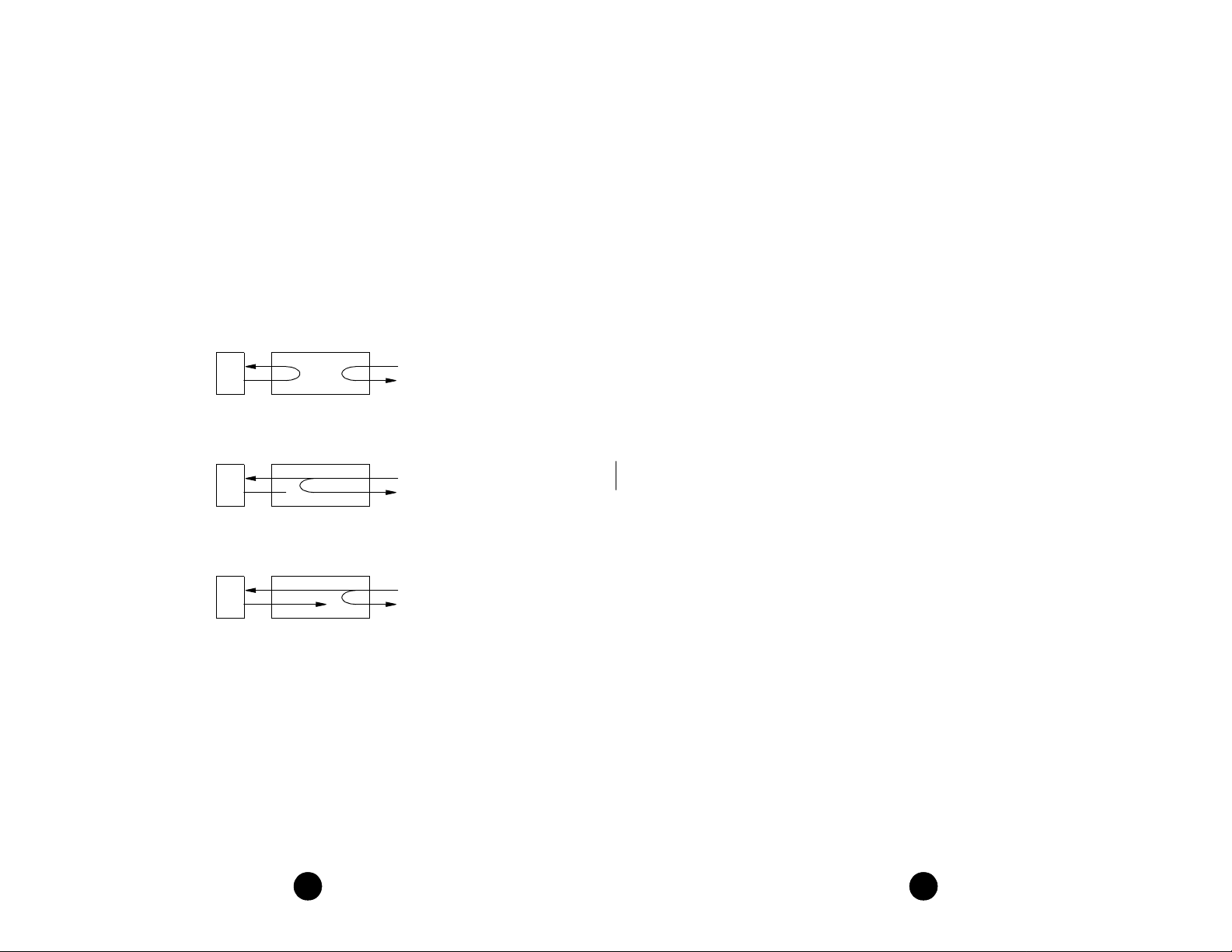
Looping Diagrams
T
ABLE OF
1. Introduction
Specifications ............................................................................................. 4
FCC Requirements .................................................................................... 5
Warranty .................................................................................................... 6
Ordering Information ................................................................................. 7
2. Installati on
.......................................................................... 4
............................................................................ 8
C
ONTENTS
Local Loopback
DTE
Remote Channel Loop
(V.54) and Data Set Loop
DTE
Channel Loop (Mandatory Loop)
DTE
NET
NET
NET
Supplied Materials ..................................................................................... 8
Unit Configuration ..................................................................................... 8
Connections...............................................................................................10
DDS Network Connection .............................................................. 10
V.35 and RS-232 Port Connection .................................................. 10
3. Operation
Testing ...................................................................................................... 13
4. Customer Service
Telephone...................................................................................................15
E-mail........................................................................................................15
World Wide Web........................................................................................15
............................................................................13
........................................................ 15
314
Page 4

1. Introduction
The TxPORT Productivity Series DDS 400 provides an economical solution to
access Digital Data Se rvice. The 400 u nit is ful ly com patible with AT&T TR62 310,
the industry specification standard for DDS. This unit is designed for standalone
(table top) use, but may be rack mounted using the optional rack mount kit. See page
page 7 for ordering information.
The 400 rear panel has three interface connectors. An RJ-48C (8 -pin) interface
allows connection to th e net work. The V.35 (34 -pin) high spe ed por t conn ector supports data rates of 2.4, 4.8, 9.6, and 56 kbps. An RS-232 (25-pi n) interface is also
provided as a substitute for the V.35 interface.
The 400 unit is configur ed through a rear panel DIP switch. LED indicator s on the
front panel alert local personnel of the unit’s line, DTE, and test status. A test switch
activates a local loopback or initiates a remote loopback and pattern test.
A power cord on each unit provides 115 VAC operation. Primary and secondary
surge protection is provided on the network side (meeting UL 1459 requirements).
Each unit provides network ALBO circuitry. This network ALBO supports a receive
range of +1 dB down to -40 d B.
Specifications
Network Interface
Line Rate: 2.4, 4.8, 9.6, 19.2, 28, 38.4, 56, and 64 kbps
Line Code: AMI
Line Impedance: Balanced 135 Ω
Input Signal: +1 to -40 dB (ALBO)
Output Signal: 3.0 V (±15%) base-peak into 135 Ω,
1.5 V (±15%) at the 9.6 kbps line rate
Line Protection: 1000 V lightning, input/output
PRODUCTIVITY SERIES 400
NORM
RL LL
TRANSPORT
DSU/CSU
®
SD RD RTS CTS RLSD LOOP
OOS
(BA) (BB) (CA) (CB) (CF) TEST
Productivity 400 DDS DSU/CSU
the V.54 code). If errors are detected, the TEST LED will be red. The NORM position deactivates the loop codes for normal op eration. Refer to the Testing section on
page 4 for further information.
Testing
The front panel test switch is used as described in the following paragraphs. Three
types of loops are shown in the diagrams on page 14.
Local Loop
LOC position. The unit loops the signal from the customer equipment (DTE IN)
back to the customer equipment (DTE OUT). It also transmits the DTE data towards
the network.
Remote Channel Loop
placing the test switch in the RL position. The unit sends a V.35 loop code in the
assigned channels to the far end for two seconds followed by two seconds of all
ones, followed by DTE data. After four seconds, the far end should be looped.
In other words, this function starts an internal test by replacing the DSU’s transmitted data with the V.54 activate code to the far end DSU e quipment for the proper
time period. Then a test pattern is sent to verify the looped channel’s integrity. If the
transmitted pattern is received error free, the LED illuminates green. If any errors are
detected, the LED illuminates red. Normal DSU operation may resume at this time
for DCE BERT testing. Returning the test switch to NORM transmits the V.54 deactivate code.
Normal (Unloop)
local loopback is removed. When the test switch is moved from REM back to
NORM, the unit sends unloop messages to the far end unit for six seconds and the
remote loopback is removed.
The following paragraphs describe other loops that may b e initiated on th e 400 unit:
Channel Loop:
current. This is a unidirectional loop that ignores the DSU transmit data and retransmits the received DDS data. Receive data is un affected and circuits CC and CF a re
forced Off.
Data Set Loop:
loop commands an d remains looped as long as each third pattern byte is the loop
command. It returns to normal operation after at least four pattern bytes that are not
the loop command. This is a unidirectional loop that retransmits the DSU received
data on the DSU transmit d ata. Receive data is unaffected and circuits CC and CF
are Off.
Local Loop:
position. This loop is bidirectional and returns the DDS receive data to the DDS
transmit line and the DSU transmit data to the DSU receive data output.
: Each unit can initiate a local loop by placing the test switch in the
: Each unit can g enerate a far end re mote channel loop by
: When the test switch is moved from LOC back to NORM, the
This loop is activated by the reversal of the simplex, 20 mA sealing
This loop is activated by the receipt of at least four consecutive
This loop is activated by pressing the front panel switch to the LL
134
Page 5

3. Operation
This chapter describes the front panel operation and test features of the TxPORT 400
DDS DSU/ CSU. The unit is controlled manually using a front panel test switch and
rear panel DIP switches. Refer to page 8 for specific information concerning DIP
switch settings.
OOS:
1)
operating status. Green indicat es DDS signal at the receiver (either customer data or
zero suppression). Amber indicates DDS signal is still present, but received data is
idle or out of service. Red indicates an insufficient signal for the DDS receiver to
operate properly.
2)
off when the data lead is a space. Therefore, the LED will vary from full intensity to
off depending on the relative number of marks and spaces.
3)
is off when the data lead is a space. Therefore, the LED will vary from full intensity to
off depending on the relative number of marks and spaces.
4)
On state at the DSU interface.
5)
state at the DSU interface.
6)
CF is in the On state at the DSU interface.
7)
either by manually depressing the loop switch or by receipt of a test command from the
facility. The LED turns red or green at the end of a V.54 test indicating the pass or fail
state of the BERT. Refer to the Testing section on page 4 for specific information.
8)
the unit in a local loop mode. Data from the DTE is looped back to the DTE. Data from
the network is looped back to the network. The RL position initiates an automated V.54
remote loop and BERT sequence of assigned data channels. The TEST LED will be
green if the test is succes sful (t he fa r end u nit l oops an d returns the data error free with
This three color Out Of Service LED indicates the DDS loop receiver’s
SD:
This green Send Data LED illuminates when the data lead is a mark and is
RD:
This green Receive Data LED illu minates wh en the d ata le ad is a m ark and
RTS:
This green Request To Send’ LED illuminates when circuit CA is in the
CTS:
This green Clear To Send LED illuminates when circuit CB is in the On
RLSD:
LOOP/TEST:
Te s t S w it c h:
This green Receive Line Signal Detector LED illuminates when circuit
This amber LED remains illuminated if the unit is in a test mode,
This 3 - position switch is used as follows: The LL position places
Power
AC Power: 115 VAC (± 10%), 150 mA maximum,
20 Watts, 73 BTU maximum
Connection: 5-foot power cord
Mechanical
Mounting: Desktop, wall, or rack m ount
Dimensions: Height: 1.75 inches (4.45 cm)
Width: 6.8 inches (17.27 cm)
Depth: 10.5 inches (26.67 cm)
Weight: 2 pounds (0.91 kg)
Industry
Standards
FCC Compliance: Part 15 Subpart B, Class A, Part 68
U.S. Safety: UL 1459
Canadian Safety: CSA C22.2 No. 225-M90
IC: CS03
Environmental
Operating Temp: 0° to 50° C (32° to 122 °F)
Storage Temp: -20° to 85° C (-4° to 185°F)
Humidity: 95% max (non-condensing)
FCC Requirements
Changes or modifications to t his unit not expressly a pproved by the party
responsible for compliance could void the user ’s authority to operate the
equipment.
This device complies with Part 15 of the FCC rules. Operation is subject to the following two conditions:
This device may not cause harmful interference.
2) This device must accept any interference received, including interference t hat may
cause undesired operat ion.
TRANSPORT
DSU /CSU
PRODUCTIVITY SERIES 400
®
OOS
SD RD RTS CTS RLSD LOOP
(BA) (BB) (CA) (CB) (CF) TEST
NORM
RL LL
This equipment has been tested and found to comply with the limits for a Class A digital device, pursuant to Part 15 of FCC Rules. These limits are designed to provide reasonable protection against harmful interference when the equipment is operated in a
commercial environment. This equipm ent generates, uses, and can radiate radio frequency energy and if not installed and us ed in accordance with the instructio n manual,
may cause harmful interfere nce to ra dio com munication s. Opera tion of this equ ipment
754321 6 8
400 DDS Front Panel
12
in a residential area is likely to cause harmful interference. The user will be required to
correct the interference at his own expense.
5
Page 6

Notice to Users of DDS service: The following instructions are provided to ensure
compliance with FCC Rules, Part 68:
1) All direct connecti ons to DDS lines must be made using standard plugs and jacks.
2) Before connecting your unit, you must inform the local telephone company of the
following information:
Port ID REN / SOC kbps FIC USOC
12 - 00492 6.0 N 2.4
4.8
9.6
38.4
56
64
04DU5-24
04DU5-48
04DU5-96
04DU5-38
04DU5-56
04DU5-64
RJ-48C jack
3) If the unit appear s to be malfunctio ning, it should be disconnected fr om the telephone lines until you learn whether the source of trouble is your equipment or the telephone line. If your equipment needs repair, it should not be reconnected until it is
repaired.
4) The unit has been de signed to pr event harm to the DDS net work. If the te lephone
company finds that th e equipment is exceeding tolera ble parameters, they can temporarily discon nect service. In this case, the telephone company will give you advance
notice, if possible.
5) Under FCC rules, no customer is authorized to repair this equipment. This restriction applies regardless of whether the equipment is in or out of warrant y.
6) If the telephone company alters their eq uipment in a manner that will affect the
use of this device, they must give you advance warning so tha t you can have the oppor tunity for uninterrupted service. Yo u will be advised of your right to file a complaint
with the FC C.
7) The attached affidavit must be completed by the installer.
8) In the event of equipment malfunction, all repairs should be performed by our
company or an authorized agent. It is the responsibility of users requiring service to
report the need for service to our company or to one of our authorized agents.
Warranty
If for any reason you must return your TxPORT product, it must be returned to the factory, shipping prepaid and packaged to the best commercial standard for electronic
equipment. TxPORT will pay shi pping c harges for d elivery on return. You are responsible for mode and cost of shi pment to TxPORT.
You must have a Return Material Authorization (RMA) number marked on the shipping package. Products sent to TxPORT without RMA numbers will be returned to the
sender unopened, at the sender’s expense. A product sent directly to TxPORT for repair
must first be assigned a Return Materials Authorization (RMA) number.
Circuit V.35 RS-232
101 A 1 Frame G round - This circuit is used to term i nate
102 B 7 Signal Ground - This circ uit is use d as the return
103 P/S 2 Transmit Data - This input is used for synchronous TD
104 R/T 3 Receive Data - This output is the da ta dec oded from
105 C 4 Request To Send - This input is a control line from the
106 D 5 Clea r To Send - This output is a DCE re sponse,
107 E 6 Data S et Ready - This outpu t is O n w hen the unit is
109 F 8 Data Carrier Detect - This output is On when the
113 U/W 24 External Transmit Cloc k - This is the synchronous
114 Y/AA 15 Transmit Clock - This output is supplied by the DCE
115 V/X 17 Receive Clock - This clock output is the timing for the
142 K 25 Test Mode - This output is On when the unit is in the
Signal Function
shields.
reference for unbalanced signals.
from the DTE. It is transmitted on the DDS side.
the incoming DDS receive data.
DTE indicati ng da ta is to be t ran smitte d . Whe n RTS is
On (space), the data transmitter, the zero suppression
circuitry, and the CTS are enabled. Whe n RTS is Off,
the transmitter sends idle code and the CTS is forced
Off.
indicating that either RTS is On or S1-8, position B, is
forcing RTS On. When S1-7 is in position B, RTS and
RLSD must be On for CTS to be On.
not in a test mode (othe r than a V.54 test).
correct data or zero suppression code is being received
and DSR is On. It is Off when either DSR is Off, the
DDS receiver has lost suffic ient signal to operate for at
least one second, or the receiver has received OOS,
OOF, idle, or loop cod es for a bout 20 U.I.
transmit clock input from the DTE. When both S1-3
and S1-4 are in the B position, this clock controls t he
frequency of the DDS transmit clock and clocks
circuit 103 (TD). When either S1-3 or S1-4 is in the
A position, this input has no effect on DDS operation.
as an external DTE timing source. It is generated from
the internal data clock or the far end transmit data. Not
available when S1-3 and S1-4 are in the B position.
RD and is always use d to time the receive data. This
clock is always derived from the DDS receive data.
Test/Loop mode.
(Note: all other pins are open)
DCE
Gnd
Gnd
In
Out
In
Out
Out
Out
In
Out
Out
Out
6 11
Page 7

Connections
The 400 DDS rear panel has thre e interface connectors: an RJ-48C DDS ne twork
connector, a V.3 5 high speed port connector, and an RS-232 connector. Each unit
comes equipped with a power cor d for 115 VAC operation (±10%).
115 VAC
V.3 5
TxPORT 400 DDS Rear Panel
13 1
RS-232
A
B
8654321 7
S1
DDS
1425
9
10
NET
81
You may obtain an RMA number from customer service at 800 -926 - 0085 extension
2282. When calling TxPORT for an RMA, please have the following information available.
• Model number and serial number for each unit.
• Reason for return and symptoms of problem.
• Warranty status (if known).
• Purchase order number to cover charges for out-of-warranty items.
• Name and phone numbe r of pe rson we can co ntact if we have questions about t he
unit(s).
• Mode of shipment required (second-day air is the normal mode o f shipment for all
returned material unless otherwise specified).
Units being returned to TxPORT should be sent to the following address.
DDS Network Connection
The network DDS facility interface is a standard RJ-48C (8-pin) modular jack with
the following pinout:
Pin Assignment
1 Network Transmit Out
2 Network Transmit Out
3 Not Used
7 Network Data In
8 Network Data In
V.35 and RS-232 Port Connection
The V.35 or the RS-232 port is automatically selected when you physically conne ct
the cable to the port. Conn ection to only one of these two co nnectors is allowed at
any one time because the internal circuitry selects the proper interface depending on
which connector has TXD applied. These ports meet all the general physical and
electrical requirements. T he V. 35 connector is a standard 34- pin female. The RS232 connector is a standard DB-25 female.
The V. 35 and RS-232 pin assignments are shown in the previous table. Only circuits serviced by the unit are listed. When two pins are listed, the first is the A differential pin and the second is the B differential pin. All balanced bipolar inputs and
outputs meet the physical and electrical speci fications at ITU V. 35. All unbal anced
bipolar inputs and outputs meet the physical and electrical specifications of ITU
V. 28.
TxPORT
127 Jetplex Circle
Madison, Alabama 35758
Ordering Information
You may require additional items to install and operate each unit. Use the following
numbers to order the bas ic unit or op tio na l eq uip m en t.
Part Number Description
F-400-00 1--111 Produc t ivity Serie s Mult irate 400 DSU/CSU unit
9-20 00-001-1 Single unit horizontal rack mount ha rdware for 19-inch equipment rac k
9-20 00-001-2 Dual unit horizontal rack moun t ha rdware for 19-inch equipment rack
9-20 00-002-1 Single unit horizontal rack mount ha rdware for 23-inch equipment rac k
9-20 00-002-2 Dual unit horizontal rack moun t ha rdware for 23-inch equipment rack
9-20 00-001-8 19-inch multi-unit rack mounting for eight units.
9-20 00-002-8 23-inch multi-unit rack mounting for ten units.
10 7
Page 8

2. Installation
This chapter contains information and instructions required to prepare the TxPORT
400 DSU/CSU for use. Included are configuration guidelines and connection
instructions.
Supplied Materials
Each 400 unit i s shippe d with th e TxPORT 400 DD S DSU/ CSU reference manual.
Yo u may require additional items for the installation and operation of the unit. Refer
to page 7 for complete ordering information.
Channel Bit Rate Select:
Positions S1- 1, S1- 2, and S1 -3 select the channel bit
rate. Refer to the table in the above diagram to determine the switch settings for a
particular bit rate. The RTS to CTS delays are multiplied by two when position S110 is in the B position.
Line Clock:
Position S1-4 selects either an internal clocking source or a loop tim-
ing source from the received data.
A - Loop timing source B - Internal line clock
Internal Clock:
Position S1- 5 selects either the DSU external clock input or the
crystal oscillator as the clocking source. This function is applicable only if position
S1 -4 is in the B position.
A - Internal master clock B - DSU external clock input
Unit Configuration
On power up, each unit is configured to the hardware settings of the option switches
(S1). Subsequent changes to these settings will not take effect until the unit has been
reset. This may be acc omplished either by removing a nd then reapplying p ower or
by pushing the test switch toward local loop LL and then quickly back to center or
NORM. The unit then recycles through its LE Ds and reads the new configuration.
S1 is a 10-position DIP switch located on the unit’s rear panel. This switch provides
the following configuration parameters.
The symbol ‘ ’ indicates that the switch pointed to is not functional unless
✍
the opposite end of the arrow is in the position shown. For example, S1-5 is
not functional unless S1-4 is in the B position.
Rate
S1-1 S1-2 S1-3
(kbps)
2.4 B B B 8 ms
4.8 A B B 4 ms
9.6 B A B 2 ms
19.2 A A B 1 ms
28 B B A .8 ms
38.4 A B A .5 ms
56 B A A .4 ms
64 A A A .3 ms
A
B
Channel
Bit Rate
RTS
to CTS
Delay
n/a
BAA
BBExternal
V.54 Loop
Inhibited
65431 7 982
Enabled
Line Clock
V.54 Loop
Internal Clock
Network
Master
Data Polarity
Normal
Inverted
Data Polarity
Circuit Assurance
Circuit Assurance
Off
On
RTS/CTS Control
RTS/CTS Control
RTS Normal Delay
10
RTS Control On
RTS -> CTS Delay
Normal
X 2
RTS -> CTS Delay
V.54 Loop Operation:
Position S1-6 enables or disables V.54 loop operation.
A - Disabled B - Enabled
Data Polarity:
Position S1- 7 determines whether data bits are inverted. In the A
position, marks equal pulse s. In the B pos itio n, spac es equ al pu lses. Receip t of OOF,
OOS, idle, or loop codes forces the DS U data to all ma rks (A position) o r spaces (B
position).
A - Normal B - Inverted
Circuit Assurance:
When position S1-8 is On, the st atus of CF (receive line signal
detector) and CA (request to send) controls the output CB (clear to send). If either
CA or CF is Off (position A), CB is Off. If CA and CF are On (position B), CB is
On.
A - Off B - On
RTS/ CTS Control:
When position S1- 9 is in the B position, CTS is forced On
regardless of the RTS input status. In the A position, the delays are determined by
S1 - 10.
A - Normal Delay B - Control On
RTS -> CTS Delay:
When position S1- 10 is in the A position, the RTS to CTS
delay is as shown in the S1- 1 , S1- 2, and S1 - 3 bit rate table. In the B position, the
delays shown are multiplied by two.
A - Normal Delay B - Delay multiplied by two
8 9
Page 9

®
TRANSPORT
Document:
Date:
Pow er
34-00222-A2.01
Addendum
Productivity Series 400 Reference Manual
June 12, 1998
The power rating, as listed on page 5 of the manual, has been revised as follows.
AC: 115 VAC, 120 mA, 7 W maximum, 23 BTU maximum
Productivity Series 400 Page 1 of 1
 Loading...