

Page 1
TRANSPORT
®
3131
Configuration Guide
Front Panel
Part Number 45-00104
Rev 1.0
3131
TRANSPORT
TEST LOOP
ALARMNETLOOPTEST
®
POWER
21 43 5 6 7
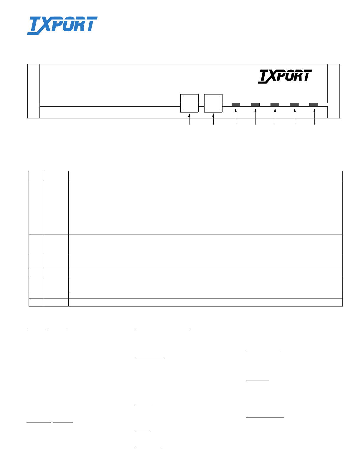
Front Panel Description
Index Item Function
1 TEST When this button is pushed once, the unit transmits five seconds of inband loop code out to the network (either LLB or V.54
depending on Switch S1-7). The indicator blinks gree n during tra nsmission of the lo op code. If S witch S2-8 is set to Clear Loop,
the data from the DTE is passed to the network and data from the network is passed to the DTE. The TEST indicator is solid
green in this mode. If Switch S2-8 is set to BERT, the test pattern last selected is transmitted toward the network. The received
pattern is compared and if it is error free, the TEST indicator remains green. If pattern errors are detected, the TEST indicator
turns red for a minimum of one second. The data ports are looped back toward the DTE during the test. If the TEST button is
pushed again, the unit transmits 5 seconds of in ba n d loop down code and returns to normal opera tin g mo de. Th e TEST in di cato r
is then turned off.
2 LOOP When this momentary pushbutton is pressed once, the unit activates a line loopback, looping the network receive data back to the
network, and looping the data from the DTE po rts back to the DTE. Th e LOOP indicato r is lit while the un it is in loop . If pushe d
again, the unit clears the loop and turns off the LOOP indicator.
3 TEST This 3-color LED flashes green when the unit is transmitting loop code. It is green continuously when BER T is on with no errors
or the unit is in a clear test. It is red when the BERT is on and is receiving errors.
4 LOOP This amber LED light continuously when the unit is in a loop mode.
5 NET This 3-color LED is green when the unit is in frame sync. It is amber when the unit is receiving a yellow alarm from the far end.
It is red when the unit is out of frame sync and/or LOS.
6 ALARM This red LED lights continuously when the unit is in an active alarm condition. It flashes if the switch configuration is invalid.
7 POWER This green LED lights continuously when power is applied to the unit.
Network Interface
Line Rate: 1.544 Mb/s (± 50 ppm)
Line Framing: D4 or ESF
Line Code: AMI or B8ZS
Input Signal: 0 to -27 dB ALBO
Connection: RJ-48C jack, 100 W (± 5%)
Output Signal: 3.0 V (±10%) ba se-peak into
100 Ω with protection
Line Build Out: 0, -7.5, -15, -22.5 dB attenuation
Transient Voltage: 1000 V protection, fused in/out
Jitter Control: Per TR 62411 and T1.403
Timing Source: Internal, recovered line clock,
external DTE, T1 DTE
Ones Density: B8ZS, Nx 56 bit stuffing,
alternate fill; TR62411
Equipment
DTE Port: V.35, 34-pin
Data Rate: Synchronous, Nx56 kps or
Clocking: Internal, Externa l, Oversam p l e
Data Invert: Independent selection each port
Interface
Nx64 kbps (where N = 1 to 24)
Specifications
Management Interfaces
Supervisory Port
Connection: 8 -pin m odular (RS-232)
Data Rates: 1.2, 2.4, 9.6, and 19.2 kbps
Diagnostics
Performance: Monitoring per TR54016, T1.403
Network Loops: Line or payload loopback
Fractional Loop: Responds to inband V.54 loop
DTE Port Loops:Bidirec ti ona l loop to DTE or Net
BERT : 511 and clear test patterns toward
network or DTE ports
Alarms
Activation: Programmable thresholds
Reporting: Front panel LE Ds, Call On
Alarm (COA)
Power
115 VAC: 0.12 A, 12 W max, 41 BTU max
Mechanical
Mounting: Desktop or horizontal rack
Dimensions: 12" (30.48 cm) wide, 1.75" (53.34
Weight: 4 pounds (1.814 kg)
Environmental
Operating Temp: 32° to 122°F (0° to 50°C)
Storage Temp: -4° to 185°F (-20° to 85°C)
Humidity: 95% maximum (non-co nde nsi ng)
Standards
TR 62411: Decemb er 1990
TR 54016: September 1989
ANSI T1.403: 1989
TR 54019A: April 1988
Industry Listings
FCC Compliance: Part 15, Subpart B, Class A
FCC Part 68 Cert: FXKUSA-22083-DE-N
NRTL: 1459, 2
IC/CSO3 Cert: 1653 6531 A
CSA Certified: LR 6229 8 (22 .5 NO 22.5 -M90)
cm) high, 9" (22.86 cm) deep
nd
Edition
Page 2
115 VAC
60 HZ
SUPV
S1
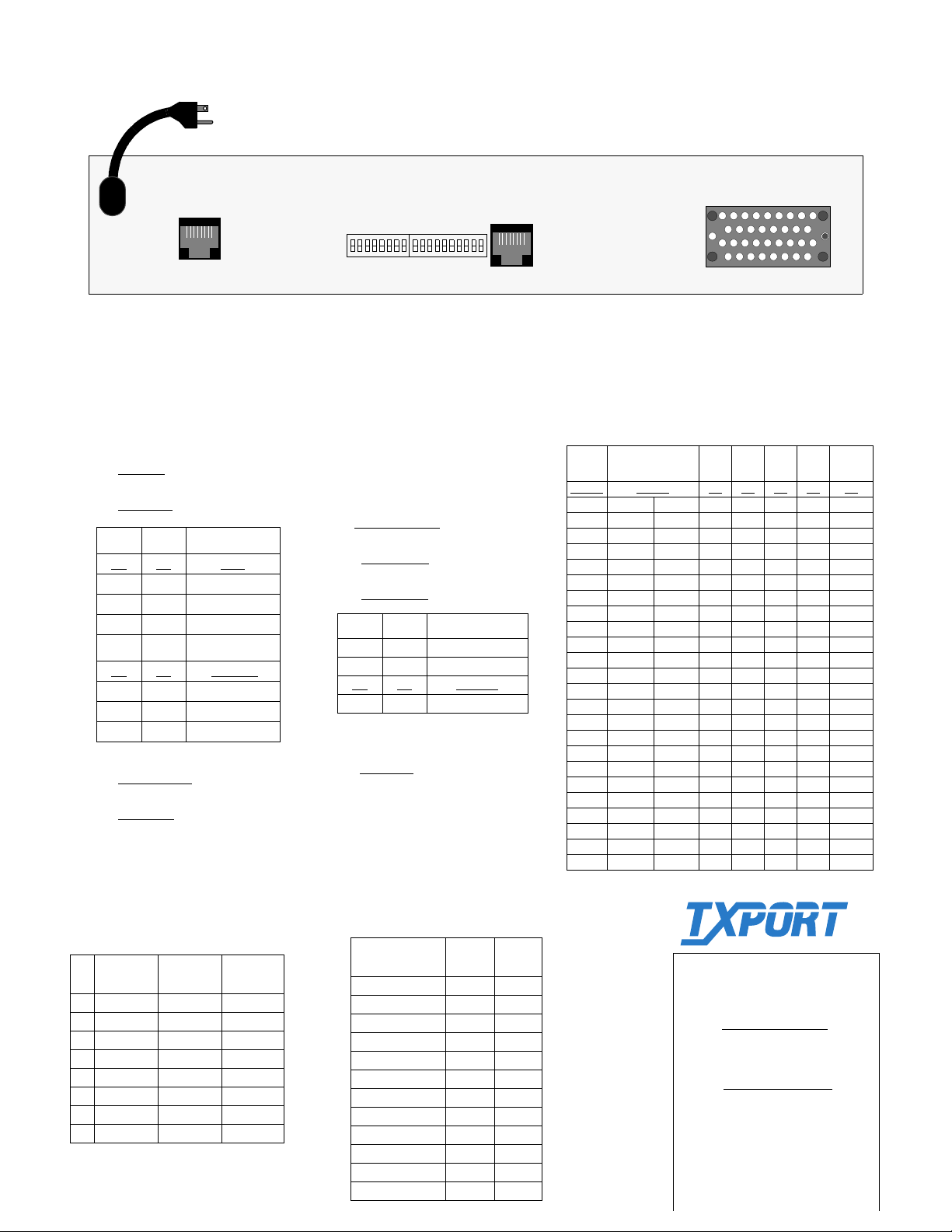
Rear Pan el
S2
NET
DATA PORT 1
Switch S1
S1-1: Set the network line framing.
Dn - ESF
S1-2: Sets the network line coding.
Dn - B8ZS
S1-3 S1-4 Network LBO
Dn
Up Dn -7.5 dB
Dn Up -15.0 dB
Up Up -22.5 dB
S1 -5 S1 -6 Timing Source
Dn
Up Dn Interna l
Dn Up Po rt 1 EXC
Up Up N/A
S1-7: Test button loop code.
Dn: LLB code
S1-8: Test button operational mode.
Dn: BERT
Up - D4
Up - AMI
Dn 0 dB
Dn Network
Up: V.54 code
Up: Clear loop
18
1
10
Switch S2
S2 -1 through S1-5:Dete rm ine the data
port bit rate. Refer to the Data Port Bit
Rates chart for configuration settings.
S2-6: Sets the channel assignme nt mode.
Dn: Contiguous
S2-7: Sets the data po rt rate multiplier.
Dn: N x 64 k
S2-8: Sets the po wer-up mode.
Dn: Switches
S2-9 S2-10 SUPV Port Rate
Up Up 1.2 kbps
Dn Up 2.4 kbps
Dn
Dn 9.6 kbps
Up Dn 19.2 kbps
Factory defaults for all swit ch settin gs are
shown underl ined
.
Switch S2-9 and S2-10 must be set before
powering the unit.
Up: Alternate
Up: N x 56 k
Up: RAM
Data Port Bit Rates
# of
DSOs
Disable
1 56 kb/s 64 kb/s Up Dn Dn Dn Dn
2 112 128 Dn Up Dn Dn Dn
3 168 192 Up Up Dn Dn Dn
4 224 256 Dn Dn Up Dn Dn
5 280 320 Up Dn Up Dn Dn
6 336 384 Dn Up Up Dn Dn
7 392 448 Up Up Up Dn Dn
8 448 512 Dn Dn Dn Up Dn
9 504 576 Up Dn Dn Up Dn
10 560 640 Dn Up Dn Up Dn
11 616 704 Up Up Dn Up Dn
12 672 768 Dn Dn Up Up Dn
13 728 832 Up Dn Up Up Dn
14 784 896 Dn Up Up Up Dn
15 840 960 Up Up Up Up Dn
16 896 1024 Dn Dn Dn Dn Up
17 952 1088 Up Dn Dn Dn Up
18 1008 1152 Dn Up Dn Dn Up
19 1064 1216 Up Up Dn Dn Up
20 1120 1280 Dn Dn Up Dn Up
21 1176 1344 Up Dn Up Dn Up
22 1232 1408 Dn Up Up Dn Up
23 1288 1472 Up Up Up Dn Up
24 1344 1536 Dn Dn Dn Up Up
S2-7
Up Dn
Disable Dn Dn Dn Dn Dn
S2-1 S2-2 S2-3 S2-4 S2-5
Rear Panel Pinouts
SUPV
Pin
Terminal
1 DCD Out DTR Out Data In
2 CTS Out RTS Out Data In
3 Frame Gnd Frame Gnd Not Used
4 Data Out Data Out Data Out
5 Data In Data In Data Out
6 Signal Gnd Signal Gnd Not Used
7 RTS In CTS In C ha ssis Gnd
8 DTR In DCD In Chassis Gnd
SUPV
Modem
Network
Data Port Pinouts
Common Name
Frame Ground 1 A
Signal Ground 7 B
Transmit Data 2, 14 P, S
Receive Data 3, 16 R, T
Request to Send 4, 19 C
Clear to Send 5, 13 D
Data Set Ready 6, 22 E
Data Term Ready 20, 23 H
Data Carrier Detect 8, 10 F
Transmit Clock 15, 12 Y, AA
Receive Clock 17, 9 V, X
Terminal Timing 24, 11 U, W
DB25
25- pin
V.35
34- pin
TRANSPORT
TxPOR T
127 Jetplex Circle
Madison, Alabama 35758
Customer Service
800-926-0085, ext. 2227
info@txport .com
Technical Support
(8 a.m. to 5 p.m. Central Time)
Toll Free:888-4TxPORT
800-285-2755 (and af-
ter-hours emergencies)
Locally: 205-772- 3770
e-mail: support@txport.com
®
Page 3

TRANSPORT
®
34-00257-A1.01
45-00104-A1.01
Addendum
Document:
Date:
Power
Industry
Listings
FCC
Requirements
PRISM 3131 Reference Manual and Configuration Guide
June 12, 1998
The power rating, as presented on page 1-2 of the manual and in the Specifications section
of the configuration guide, has been revised as follows.
AC: 115 VAC, 120 mA, 7 W maximum, 23 BTU maximum
The industry listings, as presented on page 1-2 of the manual and in the Specifications
section of the configuration guide, have been revised as follows.
FCC Compliance: Part 15 Subpart B, Class A, Part 68
rd
U.S. Safety: 1950 3
Canada Safety: CSA C22.2 No. 950-95
Industry Canada: CS03
The Notice to User s of 1.54 4 Mbps Servic e on page 1-2 of the manual has been removed.
Edition
SOC
The Service Order Code (SOC) on page 1-2 has been revised to 6.0F.
PRISM 3131 Page 1 of 1
 Loading...