

Page 1
TRANSPORT
®
310 CSU/DSU
Configuration Guide
Part Number 45-00045
Rev 2.0
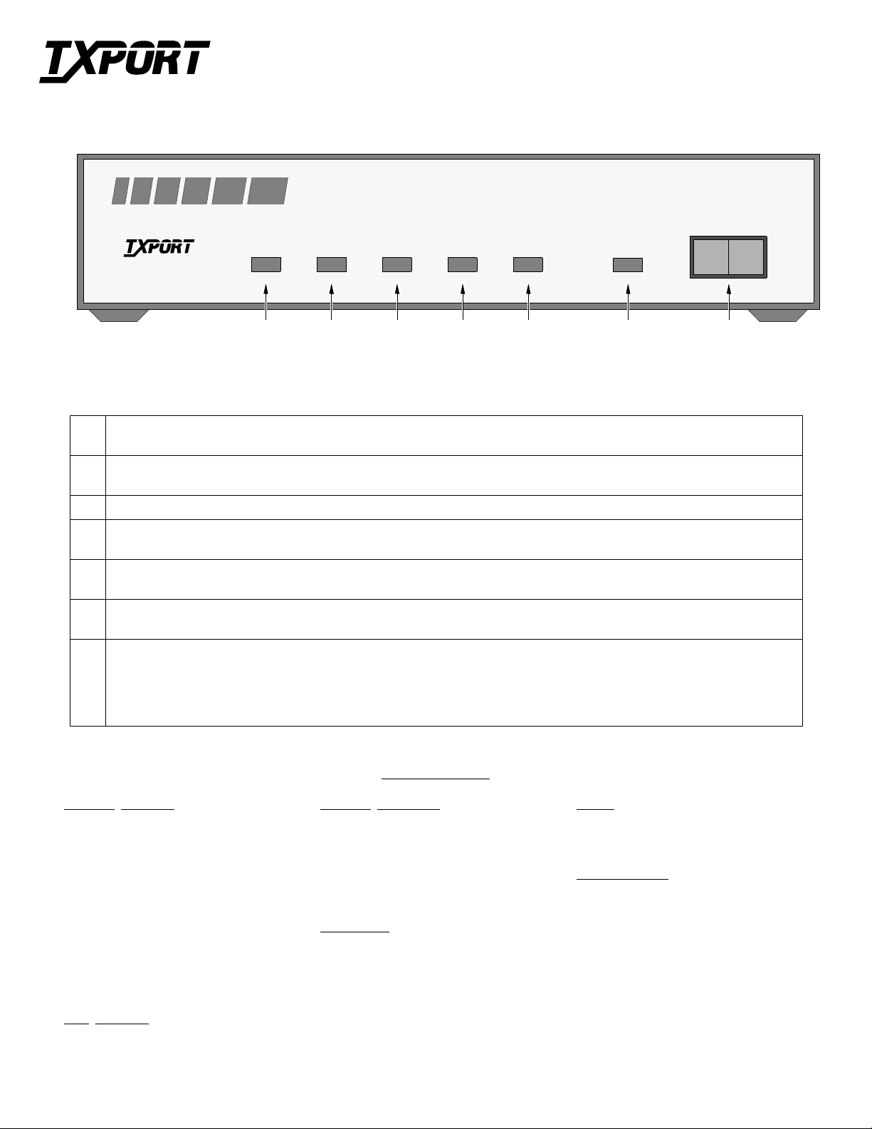
PRODUCTIVITY SERIES 310
NORM
RL LL
TRANSPORT
®
SD RD FRAME ERROR YELLOW
TEST
CSU/DSU
7654321
Front Panel Description
1
Send Data:
Therefore, the LED will vary from full intensity to off depending on the relative number of marks and spaces.
2
Receive Data:
Therefore, the LED will vary from full intensity to off depending on the relative number of marks and spaces.
3
Frame
4
Error
BPVs, FBEs, CRCs, loss of signal/loss of sync, or more than 175 zeros.
5
Yellow
This occurs if the far end terminal is out of sync with the T1 signal from the network.
6
: This amber LED remains lit if the unit is in a test mode, either by manually depressing the loop switch or by receipt of a test
Test
command from the facility.
7
Te s t Sw it ch:
mode. Data from the DTE is looped back to the DTE and is also transmitted to the network (the data from the network is open).
Depressing the switch to the ‘RL’ position initiates an automated V.54 remote loop and BERT sequence of assigned data channels. The
‘TEST’ LED will be green if the test is successful (the far end unit loops and returns the data error free with the V.54 code). If errors
are detected, the ‘TEST’ LED will be red.
This green LED lights when the S D data lead is a mark and is off when the lead is a space.
This green LED lights when the RD data lead is a mark and is off when the lead is a space.
: This green LED lights when the unit is in frame synchronization with the T1 line.
: This red LED lights if the internal alarm circuitry detects any of the following conditions from the incom ing T1 signal:
: This red LED lights if the internal alarm c ircuitry detects a rem ote (yellow) alarm signal from the far end terminal equipmen t.
This 3 - posi tion switch is used as follows: Depressi ng the switch to t he ‘LL’ position places the unit in a local loop
Network
Line Rate: 1.544 Mbps (± 50 bps)
Line Framing: D4 or ESF
Line Code : AMI or B8ZS
Line Impeda nce: balanced 100 Ω (± 5%)
Input Signal: DS1, +1 to -27 dB (ALBO)
Output Signal: 3.0 V (±15%) base-peak into
Line Build Out: 0, -7.5, -15, and -22.5 dB atten-
Line Protection: 1000 V lightning, input/output
Jitter Control: per TR62411 and T1.403
Pulse Density: per T R62411
Interface
100 Ω
uation
V.35 Interface
Data Rate: Synch, N x 56 or N x 64 kbps
Clocking: Internal or external
SPECIFICATIONS
Industry Standards
FCC: Part 15 Subpart B, Class A
UL 1459 2
CSA: C22.2 No. 225M-90
IC: CSO3 Issue 8
TR62411: December 1990
TR54019: April 1988
nd
Edition
Mechanical
Mounting: Desktop, wall, or vertical rack
Dimensions: 1.75 inches (4.45 cm) high
6.8 inches (17.27 cm) wid e
10.5 inches (26.67 cm) de ep
2 pounds (0.91 kg)
Power
AC Power: 115 V A C (± 10%), 150 mA max,
20 Watts, 73 BTU max.
Connection: 5-foot power cord
Environmental
Operating Temp: 32° to 122°F (0° to 50° C)
Storage Temp: -4° to 185°F (-20° to 85° C)
Humidity: 9 5% max (non-condensing)
Page 2

V.35
A
S1 S2
NET
81
93-130
VAC
1
B
76543219765432 8
Switch S2
A
Switch S1
A
B
DSOs Assigned
(see table at bottom)
65431 7 982
56 kbps
64 kbps
Contiguous
Alternate
Control
Control
On
Data In vert
No
Yes
Follow
Data Invert
A
A
B
B B Not Valid
A
B
Internal clock (master)
CPE clock (external)
B
A
Network clock (looped)
Timing
Source
Not
Not
ESF
54321 6 7
D4
AMI
B8ZS
Used
Used
-7.5
-15
-22.5
A
0
A
B
B B
Network
LBO
A
B
A
Network Pinout
1 Data In (R1)
2 Data In (T1)
3 /6 Not Used
4 Data Out (R)
5 Data Out (T)
7 /8 Chassis Gnd
Switch S1 Description
1 - 5 DSOs Assigned: These five positions select the bit rate and the number of DSOs assigned to the
channel (refer to the table below).
6 Rate Multiplier: Sets the multiplier for the input timing (refer to the table below). The unit oper-
ates at any data rate that is a multiple of 56 or 64 kbps.
7 Channel Assignment: The Contiguous m ode assigns the chann els as a b lock beginning at DS0
channel 1. If ‘Alternate’ is selected, channel as s i gnments are made with an idle channel fol lowin g
each data chan nel.
8 Control Lines: ‘On’ permanently sets the CTS, DSR, and CD leads to ON. With ‘Follow’, the
DSR lead fol lows T1 sy nc, th e C TS l ead fol lows RTS, and the CD lea d fol lows the de nsi ty stat us
of the incomi ng T1 signal (≥175 zeros = CD OFF). The TM line goes high when the unit is i n a
local or remote test mode.
9 Data Invert: Determ ines whether the data bits are inverted.
Switch S2 Description
1 - 2 Timing Source: This positi on selects the source of un it clocking (refer to the Swi tch S2 table).
3 Not used.
4 Network Framing: This position selects the network framing to either ESF
5 Network Coding: This position selects the network line code format to either AMI
6 - 7 Networ k LBO: Th is position selects the network LBO (line build ou t) signal level of the data
transmitte d towa rds the T1 facility (refer to the Switch S2 tabl e).
DSO S1-1 S1-2 S1-3 S1-4 S1-5 S1-6 (A) S1-6 (B)
1 B B B B B 56 kb 64 kb
2 B A B B B 112 128
3 A A B B B 168 192
4 B B A B B 224 256
5 A B A B B 280 320
6 B A A B B 336 384
7 A A A B B 392 448
8 B B B A B 448 512
9 A B B A B 504 576
10 B A B A B 560 640
11 A A B A B 616 704
12 B B A A B 672 768
13 A B A A B 728 832
14 B A A A B 784 896
15 A A A A B 840 960
16 B B B B A 896 1024
17 A B B B A 952 1088
18 B A B B A 1008 1152
19 A A B B A 1064 1216
20 B B A B A 1120 1280
21 A B A B A 1176 1344
22 B A A B A 1232 1408
23 A A A B A 1288 1472
24 A
A A A A 1344 1536
or D4.
or B8ZS.
Loops
Local Loopback
DTE
Remote Channel Loop (V.54)
DTE
CSU Line Loop (Inband or LLB)
DTE
* Signal regeneration only
NOTE: The ‘A’ position is the factory default for
all switch settings. If a particular user configuration
requires that a switch be placed in the ‘B’ direction,
then mark this sheet for future reference.
V.35 Interface
Circuit Pin # Signal Name DCE
101 A Frame Ground Ground
102 B Signal Ground Ground
103 P/S Transmit Data In
104 R /T Receive Data Out
105 C Request To Send In
106 D Clear To Send Out
107 E Data Set Ready Out
109 F Data Carrier Detect Out
113 U/W External Transmit Clock In
114 Y/AA Transmit Clock Out
115 V/X Receive Clock Out
142 K Test Mode Out
TRANSPORT
NET
127 Jetplex Circle
Madison, Alabama 35758
Sales and Marketing
800-926-0085
NET
205-772-3770
info@txport.com
RMA/ Returns
800-926-0085, ext. 2282
Technical Support
NET
*
800-285-2755
205-772-3770
support@txport.com
®
 Loading...