

Page 1
TRANSPORT
®
301 E1 NTU (CSU/DSU)
Configuration Guide
45-00106
2.0
PRODUCTIVITY SERIES 301
RL
NORM
LL
7
®
TRANSPORT
E1 CSU/DSU
SD RD
21
IN SYNC
3
ERROR4REMOTE
5
TEST
6
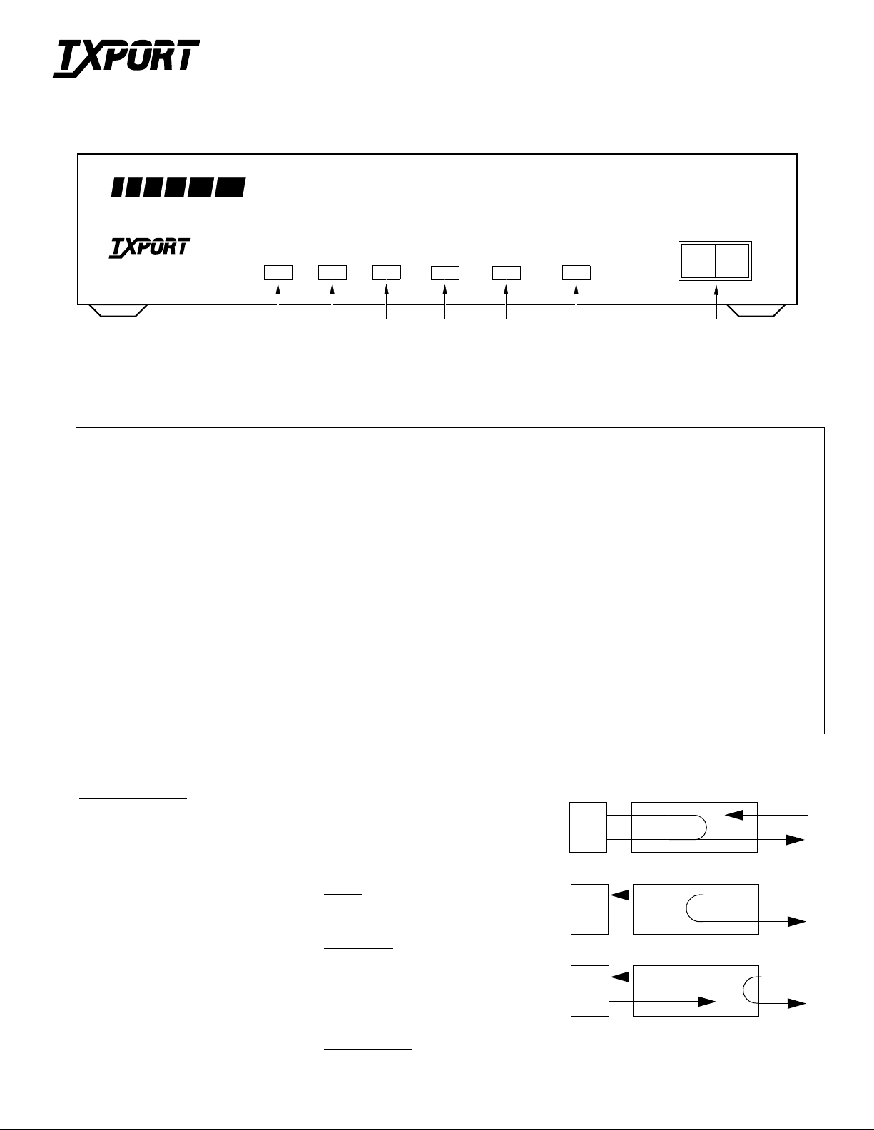
Front Panel Description
1SDGreen Illuminates wh e n t h e Send Data lead is a mark and is Off when t h e lead is a space. T he LED varies from full i ntensity to Off depend-
2RDGreen Illuminates when the Receive Data lead is a mark and is Off when the lead is a space. The LE D varies from full inte nsity to Off
3 IN SYNC Green Illuminates when the unit is in frame synchronization with the E1 line.
4ERRORRed Illuminates when the internal alarm circuitry dete cts any of the following conditions from the incoming E1 signal: BPVs, FBEs,
5REMOTERed Illuminates when the internal alarm circuitry detects a remote alarm signal from the far end terminal equipment. This occurs when the
6TESTAmber Illuminates when the unit is in te st mode by eith er a ma nual lo op switc h or a test c om man d received from the faci lity. When illu mi-
7 RL Initiates an automated V.54 remote loop and BERT sequence of assigned data channels. The TEST LED turns green if the test is successful (the
NORM Switching from L L to NO RM ta kes the unit out of test mode. Switching from RL to NOR M tra nsm it s the V.54 deactivate code.
LL
ing on the relative number of marks and spaces.
depending on the re la tive number of marks and spaces.
CRCs, loss of signal/loss of sync , or more than 175 zeros.
far end terminal is out of sync wit h the E1 signal from the network.
nated, circuit 142 (TM), pin K at the digital interface is active (On).
far end unit loops and retur ns the dat a error free with the V.54 code) and red if errors are detected in the test.
Places the unit in a local loop mode. Data from the DTE is looped back to the DTE and is also transmitted to the network (data from the network
is open).
Specifications
Network Interface
Line Rate: 2.048 Mbps (±50 ppm)
Line Framing: CCS or CRC4
Line Code: AMI or HDB3
Line Impedance: Balanced 120 Ω (±5%)
Unbalanced 75 Ω (available)
Input Signal: +6 to -43 dB
Output Signal: 3.0 V (±15%) base-peak into 120
Line Protection: Per ITU-T K.15, K.21, K.32
Jitter Control: ITU G.703
Pulse Density: ITU G.703
V.35 Interface
Data Rate: Synchronous, Nx56 or Nx64 kbps
Clocking: Internal or external
Industry Standards
FCC Compliance: Part 15 Subpart B Class A
FCC Part 68 Reg: Not Applicable
CAN/CSA: C22.2 No. 950-95
IC/CSO3: Not Applicable
UL: 1950 Third Edition
G.703 July 1995
G.704 September 1989
G.706 April 1991
G.732 1988
G.823 1993
Power
DC Power: External
Ω
Connection: 5-pin DIN
Mechanical
Mounting: Desktop, wall, or vertical rack
Dimensions: 1.75 inches (4.44 cm) High
6.8 inches (17.27 cm) Wide
10.5 inches (26.67 cm) Deep
Weight: 2 pounds (0.907 kg)
Environmental
Operating Temp: 32° to 122°F (0° to 50°C)
Storage Temp: -4° to 185°F (-20° to 85°C)
Humidity: 95 % maximu m (non- condensi ng)
DTE
DTE
DTE
Loops
Local Loopback
NET
Remote Channel Loop (V.54)
NET
CSU Line Loop (Inband)
NET
Page 2
POWER
- - -
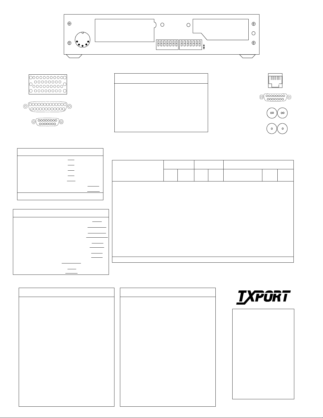
DCE Connector Options
L
F
B
J
D
N
E
A
K
C
H
M
JJ
Z
R
DD
T
X
FF
LL
BB
P
UV
Y
HH
CC
S
W
KK
EE
AA
NN
MM
V.35
113
EIA-530
1425
1
9
8
X.21
15
Switch S1
*
SW
S1-1 TS Assigned N=1
S1-2 TS Assigned N=2
S1-3 TS Assigned N=4
S1-4 TS Assigned N=8
S1-5 T S Assigned N=16
Function Position A Position B
N=0
N=0
N=0
N=0
N=0
S1-6 Rate Multiplier 56 kbps 64 kbps
S1-7 CCITT PCM PCM 30 PCM 31
*
Refer to the
Bit Rate Tables
for S1-1 through S1-5.
Switch S2
SW Function Position A Position B
S2-1 Network Line Code AMI HDB3
S2-2 Network Framing CCITT CRC4 CCITT CCS
S2-3 Network Clock
Source
S2-4 Internal Clock
Source
S2-5 CTS, DCD, and
DSR Control
S2-6 Data Polarity Data Normal Data Inverted
S2-7 T1 Network Loop
Function
Internal Clock Loop Timed
Network RXD
DSU EXTC
Clock Input
Control
On
Loop
Enabled
Crystal
Oscillator
Control
Normal
Loop
Inhibited
S1
DCE
654321 7
Network Connectors and Pinout Assignments
RJ-45 DB-15 Twin-ax Coax
Ground
Shield
Data
Input
Data
Output
Impedance 120
Pins
3, 6, 7, 8
Pins
1, 2
Pins
4, 5
Ω
Balanced
Pins
2, 4
Pins
3, 11
Pins
1, 9
120
Ω
Balanced
Terminal
Terminal
Balanced
S2
Body Body
Right
Left
120
Ω
Right
Terminal
Left
Terminal
75
Unbalanced
654321 7
A
NET
B
Network Connector Options
RJ-45
DB-15
TWIN-AX
Ω
COAX
1
9
Tx
Tx Rx
DCE Interfaces and Pinout Assignments
V.35 EIA-530 X.21
DCE Ci rcuit Name Pin
Ground Frame Ground A 101 1 AA Protect Ground 1 G
Ground Signal Ground B 102 7 AB Signal Ground 8 G
Input Transmit Data P/S 103 2/14 BA Transmit Data 2/9 T
Output Receive Data R/T 104 3/16 BB Receive Data 4/11 R
Input Request To Send C 105 4/19 CA Control 3/10 C
Output Clear To Send D 106 5/13 CB Indicator 5/12 I
Output Data Set Ready E 107 20/23 CC --- --- --Output Data Carrier Detect F 109 8/10 CF --- - -- --Input Ext. Transmit Clock U/W 113 24/11 DA --- --- --Output Transmit Clock Y/AA 114 15/12 DB --- --- --Output Receive Clock V/X 115 17/9 DD Signal Element Timing 6/13 S
Output Test Mode K 142 25 TM --- --- --Output --- --- --- --- --- Byte Timing 7/14 B
*
Byte timing is not supplied on the X.21 interface.
Circuit
Number
25-Pin Symbol Circuit Name 15-Pin Symbol
81
8
15
Rx
a
*
Bit Rate Table
TS S1 S2 S3 S4 S5 S6=A S6=B
1 B B B B B 56 kbps 64 kbps
1 A B B B B 56 kbps 64 kbps
2 B A B B B 112 kbps 128 kbps
3 A A B B B 168 kbps 192 kbps
4 B B A B B 224 kbps 256 kbps
5 A B A B B 280 kbps 320 kbps
6 B A A B B 336 kbps 384 kbps
7 A A A B B 392 kbps 448 kbps
8 B B B A B 448 kbps 512 kbps
9 A B B A B 504 kbps 576 kbps
10 B A B A B 560 kbps 640 kbps
11 A A B A B 616 kbps 704 kbps
12 B B A A B 672 kbps 768 kbps
13 A B A A B 728 kbps 832 kbps
14 B A A A B 784 kbps 896 kbps
15 A A A A B 840 kbps 960 kbps
Bit Rate Table
TS S1 S2 S3 S4 S5 S6=A S6=B
16 B B B B A 896 kbps 1.024 Mbps
17 A B B B A 952 kbps 1.088 Mbps
18 B A B B A 1.008 Mbps 1.152 Mbps
19 A A B B A 1.064 Mbps 1.216 Mbps
20 B B A B A 1.120 Mbps 1.280 Mbps
21 A B A B A 1.176 Mbps 1.344 Mbps
22 B A A B A 1.232 Mbps 1.408 Mbps
23 A A A B A 1.288 Mbps 1.472 Mbps
24 B B B A A 1.344 Mbps 1.536 Mbps
25 A B B A A 1.400 Mbps 1.600 Mbps
26 B A B A A 1.456 Mbps 1.664 Mbps
27 A A B A A 1.512 Mbps 1.728 Mbps
28 B B A A A 1.568 Mbps 1.792 Mbps
29 A B A A A 1.624 Mbps 1.856 Mbps
30 B A A A A 1.680 Mbps 1.920 Mbps
31 A A A A A 1.736 Mbps 1.984 Mbps
®
TRANSPORT
127 Jetplex Circle
Madison, Alabama 35758
Customer Service
888-4TxPORT, ext. 2227
800-926-0085, ext. 2227
Technical Support
(8 a.m. to 5 p.m. Central)
888-4TxPORT
800-285-2755
205-772-3770
Emergency After Hours
800-285-2755
 Loading...