

Page 1

4.
C
USTOMER
TxPORT provides easy access to customer support information 24
hours a day, seven days a week through a varie ty of services incl uding telephone, e-mail, and the world wide web.
S
ERVICE
Telephone
To speak directly with a TxPORT customer service representative or
send a facsimile you may dial any one of the following numbers.
Toll Free: 800-926-0085 or 888-4TxPORT
Local: 205-772-3770
FAX: 205-772-3388
E-mail
You can request sales and marketing in formation or pose a tec hnical
support question about your TxPORT product with direct e-mail
access.
Sales & Marketing:info@txport.com
Technical Support: support@txport.com
P
RODUCTIVITY SERIES
TRANSPORT
300/310
T1/FT1
CSU/DSU
®
World Wide Web
You can access product informa tion, tec hnical supp ort, news releases
and more from our world wide web site by entering our URL into
your internet br owser.
http://www.txport.com
34-00199
O
CTOBER
1 16
1997
Page 2
OPYRIGHT/LIABILITY
C
© 1997 TxPORT, All rights reser ved. No par t of th is pu blicati on may be repro duced, transmitted, transcribed, stored in a retrieval system, or translated into
any language in any form by any means without the written permission of
TxPORT.
Reorder # 34-00199
nd
Edition, October 1997
2
TxPORT shall not be liab le for er ror s cont ained h erei n or f or in cide ntal o r consequential damages in connection with the furnishi ng, performance, or use of
this material. TxPORT reserves the right to revise this publication from time to
time and make chan ges in content without ob ligation to notify any perso n of
such revision changes.
Contents of this p ublication m ay be prelimi nary and/o r may be changed at any
time without notice and shall not be regarded as a warranty.
Documentation Disclaimer
pattern is received error free, the LED turns ‘green’. If any errors are detected, the LED
turns ‘red’. Normal DSU operation may resume at this time for DCE BERT testing.
Returning the test switch to ‘NORM’ transmits the V.54 deactivate code.
Normal (Unloop): When the test switch is moved from ‘LL’ back to ‘NORM’, the local
loopback is removed. When the test switch is moved from ‘RL’ back to ‘NORM’, the
unit sends unlo op mess age s t o the far en d u nit for si x s econds and t he rem ote lo opb ack
is removed.
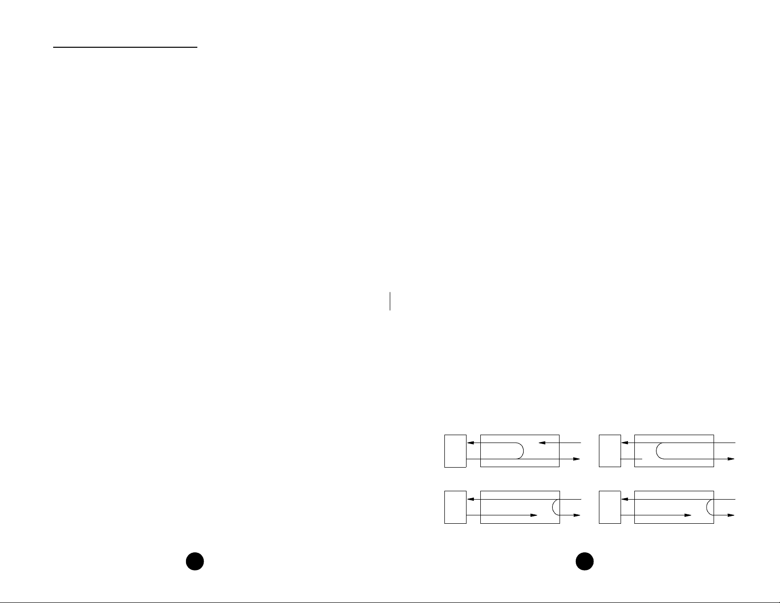
The following paragraphs de scribe other loops that may be initiat ed on the 300/ 310
units. Refer to the looping diagrams below for further information.
CSU Inband LLB: Each unit can be looped remotely by generating towards it a standard CSU line loopb ack code (000 01 repeatin g for ≥ 5 seco nds, framed or unframed) .
Once looped, the received signal from the T1 facility (NET IN) is regenerated and
transmitted back to the T1 facility (NET O UT). The signal from the network is also
passed to the DTE port.
CSU Inband Unloop: Each unit can be unlooped remotely by generating towards it a
standard CSU lin e unloop code (001 repeating for ≥ 5 seconds, framed or unframed).
T1.403 LLB: The 300 unit supports the T1.403 line loopback command (the FDL
LLB format is 00001110 1111 1111). Once looped, the received signal from th e T1 facility (NET IN) is regenerated and transmitted back to the T1 facility (NET OUT). The
signal from the network is also passed to the DTE port.
T1.403 LLB Unloop: The 30 0 unit supports the T1.403 FDL line loopback unloop
command messages (0 0111000 11111111 repeating).
T1.403 /54016 PLB: The 300 unit supports the T1.403 FDL payload loopback command messages (00111000 11111111 repeating).
T1.403/54016 PLB Unloop: The 300 un it supports the T1.4 03 FDL payload loopback unloop comman d message (00110010 11111111 repeating).
TxPORT makes no representation or warranties of any kind whatsoever with
respect to the contents hereof and specifically disclaims any implied warranties
of merchantability or fitness for any particular purpose.
2
Local Loopback
DTE
CSU Loop (FDL/PLB)
DTE
* Signal, frame, and CRC regeneration
Looping Diagrams
NET
NET
*
DTE
CSU Line Loop (Inband or FDL/LLB)
DTE
15
Remote Channel Loop (V.54)
NET
NET
*
* Signal regeneration only
Page 3
Productivity 300/310 DSU/CSU (model 300 shown)
PRODUCTIVITY SERIES 300
®
TRANSPORT
CSU/DSU
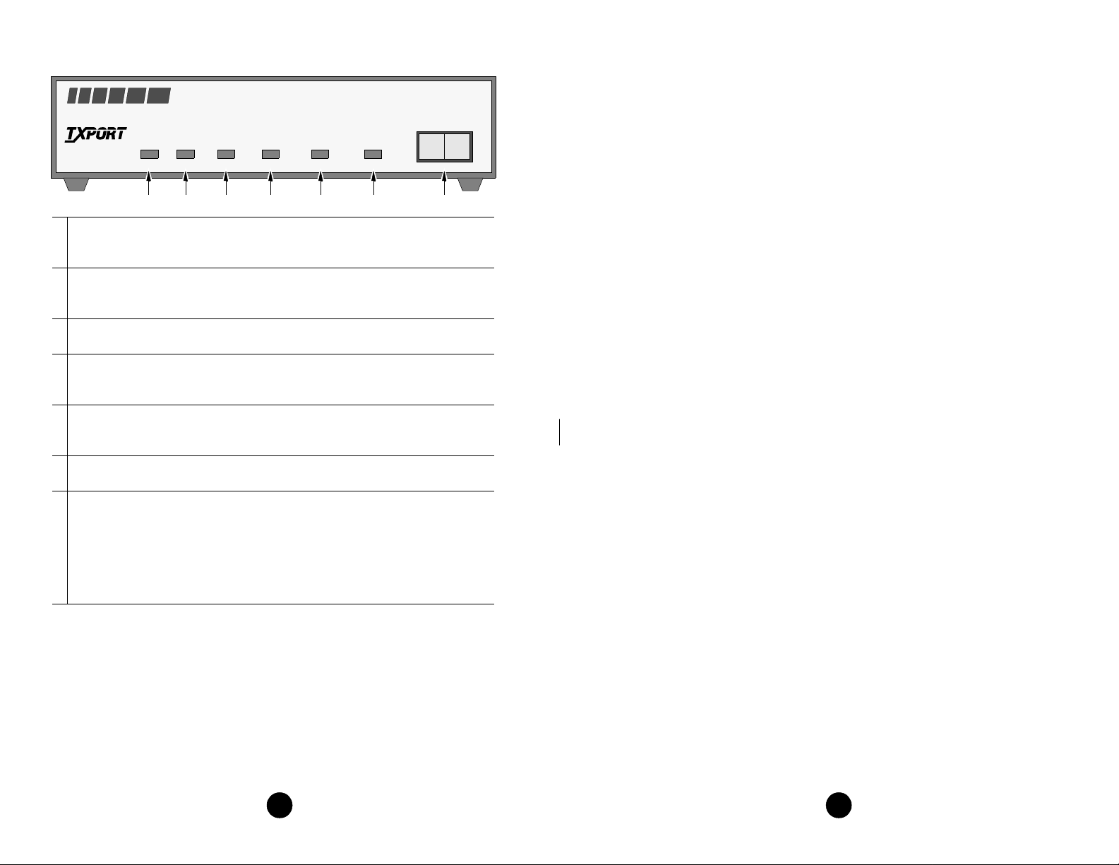
1 Send Data: This green LED lights when the SD data lead is a mark and is off
when the lead is a space. Theref ore, the LED will vary from full intensity to off
depending on the rela tive number of marks and spaces.
2 Receive Data: This green LED lights when the RD data lead is a mark and is off
when the lead is a space. Theref ore, the LED will vary from full intensity to off
depending on the rela tive number of marks and spaces.
3 Frame: This green LED lights when the unit is in frame synchronization with the
T1 line.
4 Error: This red LED lights if the internal alarm circuitry detects any of the fol-
lowing conditions from the incoming T1 signal: BPVs, FBEs, CRCs, loss of
signal/loss of sync, or more than 175 zeros.
5 Yellow: This red LED lights if the internal alarm circuitry detects a remote (yel-
low) alarm signal from the far end terminal equipment. Thi s occurs if the far end
terminal is out of sync with the T1 signal from the network.
6 Test: This amber LED remains lit if the unit is in a test mode, either by manually
depressing the loop switch or by receipt of a test command from the facility.
7 Test Switch: This 3-position switch is used as follows: Depressing the switch to
the ‘LL’ position places the unit in a local loop mod e. Data fro m the DTE is loop ed
back to the DTE and is also transmitted to the network (the data from the network
is open). Depressing the switch to the ‘RL’ position initiates an automated V.54
remote loop and BERT sequence of assigned data channels. The ‘TEST’ LED will
be green if the test is su ccessful (the far end u nit loops and return s the data error
free with the V.54 code). If errors are detected, the ‘TEST’ LED will be red.
Remote Channel Loop: Each unit can generate a far end remote channel loop by
placing the test switch in the ‘RL’ position. The unit sends a V.35 loop code in the assigned channels to the far end for two seconds fol lowed by two seconds of all ones, followed by DTE data. After four seconds, the far end should be looped.
In other words, this function starts an internal test by replacing the DSUs transmitted
data with the V.54 activate code to the far end DSU equipment for the proper tim e period. Then a test pattern is sent to verify the looped channel’s integrity. If the transmitted
SD RD FRAME ERROR YELLOW TEST
NORM
RL LL
754321 6
ABLE OFCONTENTS
T
1. General
..................................................................4
Specifications ................................................................................ 5
FCC Requirements ........................................................................ 6
Warranty ....................................................................................... 7
Ordering Numbers ........................................................................ 8
2. Installation ..............................................................8
Supplied Materials ........................................................................ 9
Unit Configuration ........................................................................ 9
Configuration Switch S1 ....................................................... 9
Configuration Switch S2 ....................................................... 11
Connections .................................................................................. 12
V.35 Port Connection ............................................................ 12
Network Connection .............................................................. 13
3. Operation ..............................................................13
Testing .......................................................................................... 13
4. Customer Service...................................................16
Telephone.......................................................................................16
E-mail.............................................................................................16
World Wide Web....................... ...... ...... ........................................16
314
Page 4

1. G
The TxPORT Productivity Series CSU /DSU models 3 00 and 310 provide an economical solution for interfacing customer high speed digital applications to industry
standard T1 or fractional T1 facilities. These units are designed for standalone
(tabletop) use, but they may be rack mounted (refer to the Ordering Numbers section
on page 8).
ENERAL
The connector is a standard 34-pin female V.35. Only circuit s servic ed by the uni t are
listed. When two pins are listed, the first is the “A” differential pin and the second is
the “B” differential pin.
All balanced bipolar inputs and outputs meet the physical and ele ctrical specifications
at ITU V.35. All unbalanced bipolar inpu ts and ou tput s mee t the physi cal and elect ri cal
specifications of ITU V.28.
Network Connection
The main difference between the model 300 and the 310 is in the function of a DIP
switch which cont rols the ESF operat ing mode on the 3 00, but has no function on
the 310 unit. Any resulting differences will be noted in the appropriate places
throughout this manual.
The 300 unit is fully compatible with both ANSI T1.403 and AT&T 54016 ESF
performance monitoring, testing, and reporting requirements. Both units support
D4/ESF framing and AMI/B8ZS line encoding.
LED indicators are provided on the fron t panel of each unit to alert loc al personnel
of alarm conditions, loop/test status, and DTE port activity. A test switch allows
local and remote loops to be activated. The 300 unit also supports FDL loopbacks.
The 300 and the 310 rear panels have two interface connectors - an RJ-48C network
interface connector and a V.35 high speed port conne ctor. The V.35 port supports
data rates up to 1.536 Mbps (in increments of either 56 kbps or 64 kbps).
A power cord on each unit provides 115 VAC operation. Primary and secondary
surge protection is prov ided on the network side (meeting UL 1459 requirements).
Each unit provides network automatic line build out (ALBO) circuitry. This network
ALBO supports a r eceive range of +1 dB down to -27 dB. These unit s also provide
network line build out (LBO) circuitry. The transmit LBO is user selectable from 0
dB down to -22.5 dB.
The network T1 facility interface is a standard RJ-48C 8 -pin modular jack with the
following pinout:
Pin Assignment
1 Data In
2 Data In
3Not Used
4 Data Out
5 Data Out
6Not Used
7/8 Chassis Ground
3. O
This chapter describ es the front panel opera tion and test features of th e TxPORT 300
and 310 CSUs. Both units are controlled manually using a front panel test switch and
rear panel DIP switches (the DIP switches are discussed in the ‘Installation’ chapter).
The controls, indicators and test features are identical for both units except for references to T1.403 or 54016 loops, which are specific to the 300 unit only.
PERATION
TRANSPORT
CSU/DSU
Productivity 300/310 DSU/CSU (model 300 shown)
PRODUCTIVITY SERIES 300
®
SD RD FRAME ERROR YELLOW TEST
NORM
RL LL
Testing
The front panel test switch is used as described in the following paragraphs. Four types
of loops are shown on page 15.
Local Loop: Each unit can initiate a local loo p by placing th e test swi tch in the ‘L OC’
position. The unit loops the signal from the customer equipment (DTE IN) back to the
customer equipment (DTE OUT). It also transmits the DTE data towards the network.
134
Page 5

unit generates a PRM (performance report message) once every second and responds to
T1.403 messages only.
A - ESF B - D4
Network Coding: Position S2-5 sets the network line code format. With AMI codin g,
each unit converts data to the AMI format from th e DTE port towards the network. Incoming AMI data is converted internally to NRZ data and passed to the DTE port. In
the B8ZS mode, the unit substitutes any 8 -zero data with a B8ZS code and transmits it
towards the network. B8ZS data from the network is converted to NRZ data internally.
When the unit is operating ‘cl ear channel’, it ca n be configured to B8ZS for ones density control.
- AMI B - B8ZS
A
Network LBO: Positions S2-6 and S2-7 set the network line build out signal leve l of
data transmitted towards the T1 facility. The output level is factory set at 0 dB
. It may
be attenuated by -7.5 dB, -15 dB, or -22.5 dB if operating conditions require the
change (refer to the Switch S2 diagram for switch settings). The telco should provide
the proper setting to the user. If unsure of the exact setting, then let it remain at 0 dB.
Specifications
Network Interface
Line Rate: 1.544 Mbps (± 50 bps)
Line Framing: D4 or ESF
Line Code: AMI or B8ZS
Line Impedance: balanced 100 Ω (± 5%)
Input Signal: DS1, +1 to -27 dB (ALBO)
Output Signal: 3.0 V (±15%) base-peak into 100 Ω
Line Build Out: 0, -7.5, -15, and -22.5 dB attenuation
Line Protection: 1000 V lightning, input/output
Jitter Control: per TR62411 and T1.403
Pulse Density: per TR62411
V.35
Interface
Data Rate: Synchronous, N x 56 or N x 64 kbps
Clocking: Internal or external
Connections
The model 300 and 310 rear pan el s have two inter face conn ecto rs - an RJ- 48C ne twork
interface connector and a V.35 high speed port connector. The following paragraphs explain the network and V.35 connections. Each unit comes equipped wi th a power cord
for 115 VAC (±10%) operation.
V.35 Port Connection
The V.35 port meets al l the general physical and electrical require ments. It supports
TM and auto clock scan. The V.35 pin assignment s are as follows.
Circuit Pin # Signal Name DCE
101 A Frame Ground Ground
102 B Signal Grou nd Ground
103 P/ S Transmit Data In
104 R/T Receive Data Out
105 C Request To Send In
106 D Clear To Send Out
107 E Da ta Set Ready Out
109 F Data Carrier De te ct Out
113 U/W External Transmit Clock In
114 Y/AA Transmit Clock Out
115 V/X Receive Clock Out
142 K Test Mode Out
Industry
Standards
FCC: Part 15 Subpart B, Class A
UL 1459 2nd Edition
CSA: C22.2 No. 225-M90
IC: CSO3 Issue 8
ANSI T1.403: 1989 (300 only)
TR54016: September 1989 (300 only)
TR62411: December 1990
TR54019A: April 1988
Power
AC Power: 115 VAC (± 10%), 150 mA ma x, 20 Watts, 73 BTU max .
Connection: 5-foot power cord
Mechanical
Mounting: Desk top, wall, or vertical rack
Dimensions: 1.75 inches (4. 45 c m) hi gh, 6. 8 inch es (1 7. 27 cm ) wi de , 10.5
inches (26.67 cm) deep
Weight: 2 pounds (0.91 kg)
Environmental
Operating Temp: 32° to 122°F (0° to 50° C)
Storage Temp: -4° to 185°F (-20° to 85° C)
Humidity: 95% max (non-condensing)
12
5
Page 6

FCC Requirements
54016
ESF
AMI
T1.403
D4
B8ZS
54321 6 7
B
A
A
A
B
A
Network clock (looped)
Internal clock (master)
CPE clock (external)
Timing
Source
Network
LBO
B B
B
A
A
A
B
A
0
-22.5
-7.5
-15
A
B
Changes or modifications to this unit not expressly approved by the
party responsible for compliance could void the user’s authority to operate the equipment.
This device complies with Part 15 of the FCC rules. Operation is subject to the following two conditions:
1) This device may not cause harmful interference.
2) This device must accept any interference received, incl uding interference that
may cause unde s i re d operation.
This equipment has been tested and found to comply with the limits for a Class A
digital device, pur suant to Part 15 of FCC Rules. These l imits are designed to provide reasonable protection against harmful interference when the equipment is operated in a commercial environment. This equipment generates, uses, and can radiate
radio frequency energy and if not insta lled and used in acco rdance with the instru ction manual, may cause harmful interference to radio commun ications. Operation of
this equipment in a residen tial area is likely to cau se harmful interferenc e. The user
will be required to correct the interference at his own expense.
Notice to Users of 1.544 Mbps Se rvice: The foll owing instructions are provided to
ensure compliance with FCC Rules, Part 68:
1) All direct connections to T1 lines must be ma de usin g sta nd ard p lug s and ja c ks.
2) Before co nnecting your unit, you must inform the local tel ephone company of
the following information:
quirements are maint ained by the idle channe ls rather that placing any restrictions on
the high speed data.
A - Contiguous B - Alternating
Control Lines: Position S1 -8 selects the control line operation. Control lines supported are RTS, CTS, DSR, CD, LL, and TM. With ‘On’ selected, the CTS, DSR, and CD
leads are permanently set to ON. With ‘Follow’ selected, the DSR lead follows T1
sync, the CTS lead fol lows RTS, and the CD lead follows the density st atus of the in coming T1 signal (≥175 zeros = CD OFF). The TM line goes high when the unit is in a
local or remote test mode.
- On B - Follow
A
Data Invert: Position S1 -9 determines whether the data bits are inverted. The ‘Yes’
mode is useful in maintaining ones density control in certain data applications, such as
HDLC and X.25.
A - No B - Yes
Configuration Switch S2
Switch S2 is a 7- position DIP switch located on the CSU rear panel. This switch provides the following configuration parameters:
Port ID REN / SOC FIC USOC
12 - 00492 6.0 N 04DU9-BN
RJ-48C jack
04DU9-DN
04DU9-1ZN
04DU9-1KN
04DU9-1SN
3) If the unit appears to be malfunctioning, it should be disconnected from the
telephone lines u ntil you learn whether the source of trouble is your equi pment or
the telephone line. If your equipment needs repair, it should not be reconnected until
it is repair ed.
4) The u nit ha s been desig ned to prevent harm to t he T1 net work. I f the tele phone
company finds that the equi pment is exceeding to lerable parameters, they can t emporarily disconnect service. In this case, the telephone company will give you
advance notice, if possible.
5) Under FCC rules, no customer is authorized to repair this equipment. This
restriction applies r egardless of whether the equipment is in or out of warranty.
Timing Source: Positions S2- 1 and S2- 2 determine the source of unit clocking as
shown in the above diagram.
Operating Mode (Model 300 only): Position S2- 3 sets the ope rating mo de of th e 300
unit. In the 5401 6
mode, the unit responds on ly t o 5401 6 CSU me ssages. In the T1 . 403
mode, the unit respon ds to ANSI loop/ unloop commands an d generates a PRM every
second, but will not respond to 54016 mess ages. The two modes are exclusive of each
other.
A - 54016 B - T1.403
Network Framing: Position S2 - 4 sets the unit to the line framing of the network. In
the ESF mode, the units can be configured for either the T1.403 or 54016 mode. In the
54016 mode, th e 300 unit responds to all 54016 messages. In the T1.403 mode, the 300
6 11
Page 7

DSOs Assigned: Positions S1 -1 through S1- 5 select the bit rate and the number of
DSOs assigned to the channel (refer to the following table).
DSO S1 -1 S1-2 S1-3 S1-4 S1-5 S1-6 (A) S1- 6 (B)
1 B B B B B 56 kb 64 kb
2 B A B B B 112 128
3 A A B B B 168 192
4 B B A B B 224 256
5 A B A B B 280 320
6 B A A B B 336 384
7 A A A B B 392 448
8 B B B A B 448 512
9 A B B A B 504 576
10 B A B A B 560 640
11 A A B A B 616 704
12 B B A A B 672 768
13 A B A A B 728 832
14 B A A A B 784 896
15 A A A A B 840 960
16 B B B B A 896 1024
17 A B B B A 952 1088
18 B A B B A 1008 1152
19 A A B B A 1064 1216
20 B B A B A 1120 1280
21 A B A B A 1176 1344
22 B A A B A 1232 1408
23 A A A B A 1288 1472
24 A
A A A A 1344 1536
Rate Multiplier: Position S1-6 is used to set the multiplier for the input timing (refer
to the table above). The unit can operate at any data rate that is a multiple of 56 or 64
kbps. Selecting ‘Nx 6 4K’ provides port bit rates that are multiples of 64 kbps. The ones
density requirements of the T1 network line must be ensured in this mode. Selecting
‘N x56K’ allows port bit rates that are multiples of 56 kbps. The unit maintains ones
density for the selected DS0 channel in this mode by stuffing bit 7.
A - 56 kbps B - 64 kbps
Channel Assignment: Position S1- 7 selects either the ‘Contiguous
’ or ‘Alternating’
data insertion mode. The Contiguous mode assigns the channels as a block beginning
at DS0 channel 1. For examp le, if the por t data rate is t o be 256 kbps, t he unit would
assign network channel s 1 through 4 to the high speed port (4 x 64 = 256 kbps).
6) If the telephone company alters their equipment in a manner that will affect the
use of this device, th ey must give you advance warning so that you can have the
opportunity for uninterrupted service. You will be advised of your right to file a
complaint with the FCC.
7) The attached affidavit must be completed by the installer.
8) In the event of equipment malfunction, all repairs should be performed by our
company or an authorized agent. It is the responsibility of users requiring service to
report the need for service to our comp any or to one of our authorized agents.
Warranty
If for any reason yo u must return your TxPORT product, it must be re turned to the
factory, shipping prepaid and packaged to the best commercial standard for electronic equipment. TxPORT will pay shipping charges for delivery on return. You are
responsible f or mode and cost of shipment to TxPORT.
You must have a Return Material Authorization (RMA) number marked on the shipping package. Pr oducts sent to TxPORT without RMA numbers will be returned to
the sender unopened, at the sender’s expense. A product sent directl y to TxPORT for
repair must first be assigned a Return Materials Authorization (RMA) number.
You may ob ta in an RMA nu mbe r fr om cust om er serv i ce a t 800-926-0085 extension
2282. When calling TxPORT for an RMA, please have the following information
available.
• Model number and serial number for each unit.
• Reason for return and symptoms of problem.
• Warranty status (if known).
• Purchase order number to cover charges for out-of-warranty items.
• Name and phone number o f person we can contact i f we have questions about
the unit(s).
• Mode of shipment re quired ( secon d-day ai r is th e normal mode of sh ipment for
all returned material unless otherwise specified).
Units being returned to TxPORT should be sent to the following address.
TxPORT
127 Jetplex Circle
Madison, Alabama 35758
If ‘Al ternating’ is sel ected, channel assignments are made with an idle channe l following each data cha nnel. Using the sam e example, data woul d be carried on c hannels 1,
3, 5, and 7 and channels 2, 4, 6, and 8 would be set to idle (the idle bit code is
11111111). The advantage of alter nate channel assig nment is that T1 ones densit y re-
10 7
Page 8

Ordering Numbers
Supplied Materials
Both the TxPORT 300 and 310 units are shipped from the factory with the 300/ 310
DSU /CSU reference manual. The user may require additional items for the installation
and operation of each unit. Use the following numbers to order the basic unit or
optional equipment.
Part Number Description
F-300-001--111 300 ESF CSU productivity series unit
F-310-001--111 310 CSU productivity series unit
9-2000-001-1 Single unit horizontal rack mount hardware for 19-inch equipment rack
9 -2000-001-2 Dual unit hori zontal rack mount hardware for 19-inch equipm ent rack
9-2000-002-1 Single unit horizontal rack mount hardware for 23-inch equipment rack
9-2000-002-2 Single unit horizontal rack mount hardware for 23-inch equipment rack
NSTALLATION
2. I
This chapter contains information and instructions required to prepare the TxPORT
300 and 310 DSU/CSUs for use. Included are configuration guidelines and connection
instructions.
The only difference between the two units is that the 300 has two ESF operation
modes. Therefore, the DIP switch position that controls this mode is not functional on
the 310 unit.
The TxPORT 300 Productivity Series units are shipped from the factory with the 300/
310 DSU/CSU reference manual. The user may require additional items for unit
installation and operation. Refer to page8 for complete ordering information.
Unit Configuration
The following sections descr ibe the configuration of the 300 and 310 mo dels. These
units were designed to be operat ed from manual DIP switch con trol. Refer to the diagrams in this chapter for switch locations.
On power up, each unit is configured to the hardware settings of the option switches.
Subsequent changes to these settings will not take effect until the unit has been reset.
This may be acc omplished e ither by removing and then reapplying power or by pushing the test switch toward local loop ‘LL’ and then quickly back to ‘NORM’. The unit
will then recycle through its LEDs and read the new configuration.
Configuration Switch S1
Switch S1 is a 9- position DIP switch located on the CSU rear panel. This switch provides the following configuration parameters:
56 kbps
Contiguous
Control
Data Invert
On
Follow
No
Switch
S1
Yes
Data Invert
A
B
DSOs Assigned
(see table)
65431 7 982
Alternate
Control
64 kbps
TxPORT Models 300 and 310 Rear Panel
Throughout this manual, all factory default settings are shown underlined
‘A’ position is the default setting for all switches).
✍
8 9
(the
93-130
VAC
V.35
A
B
S1 S2
9
NET
81
76543218654321 7
Page 9

®
TRANSPORT
Document:
Date:
Pow er
Industry
Listings
34-00199-A2.01
Addendum
Productivity Series 300 Reference Manual
June 12, 1998
The power rating and industry listings, as presented on page 5 of the manual, have been
revised as fo llows.
AC: 115 VAC, 120 mA, 8 W maximum, 27 BTU maximum
FCC Compliance: Part 15 Subpart B, Class A, Part 68
nd
U.S. Safety: 1459 2
Canada Safety: CSA C22.2 No. 255-M90
Industry Canada: CS03, Issue 8
Edition
Productivity Series 300 Page 1 of 1
 Loading...