

Page 1
2100 CSU
Configuration Guide (chassis version)
45 -00033
Rev E
7654321
LOC
S2
TO
NET
MON
DTE
FRM
STATUS
ACO
LOS
AIS
LOOP
DENSITY
SET
RESET
BPV
ACO SW
2100 CSU
31 4 5 14
2 6 7 8 9 10 11 12 13
ERR
FAR
MON
TO
DTE
NET
FRM
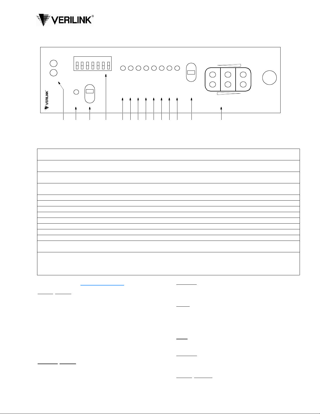
Front Panel Description
1 Status: The green LED lights when the unit is powered and operat ing normally. The red LED light s if an alarm exce eding
thresholds is detected or another type of uni t failure e xists.
2 ACO: This LED lights if the Alarm Cut Off switch is placed in the left On position. It i ndicates that the alarm relay contacts are
disabled.
3 AC O S W: This switch con trols the alar m r elay circuitry. The right On positi on disables the alarm relay cont acts. The left Off
position enables the contacts to report alarm conditions.
4 Switch S2: This seven-position DIP switch is used for unit configurat ion. The black squares indicate the direction of fa ctory
default se ttings. Refer to the switch dia g ram and table on ba c k.
5 BPV: This LED ligh ts (0.1 seconds minimum) for each occurrence of bipolar violations from the network.
6 LOS: This LED lig hts to indicate t h at a loss of signal is detected from th e network.
7 AIS: This LED light s if an unframed all-ones condit ion (alarm indica tion signal) is detected from the network.
8 LOOP: This LED lights to indicate that the unit is in a line loopback condition.
9 DENSITY: This LED lights if the ones density of the receiv ed data from the DTE is less than 12.5 percent .
10 SET: This LED flashes when the set code is transmitted. It lights constantly when the set code is received.
11 RESET: This LED flashes when the reset code is transmitted. It lights for five seconds when the reset code is received.
12 ERR: This LED flashes if a BERT pattern error is received during network testing.
13 Test Switch: This thr ee-po s iti o n sw i tc h is use d for perform in g a net work test or a loca l lo o pb a ck . T he L O C se tt in g invokes a
bidirectional loop. If the unit receives a loop code from the network, then the setting of Switch S3-7 applies.
14 Test Jacks: These bantam jacks provide access to the T1 line on the DTE side as follows – the top two jacks break connection to
the DTE and make connection to the unit in the direction of the net w ork, the middle two ports are used for monitoring the signals
passing through the unit ( between the DTE and the network), and the bottom two port s break connection to the unit and mak e
connection to the DTE.
SPECIFICATIONS
Network Interface
Line Rat e: 1.544 Mbps, ± 50 ppm (internal clock) , ± 200 bps (thro ugh mo de)
Line Framing: D4 or ESF (transparent)
Line Cod e: AMI or B8ZS
Input Signal: DS1, 0 to -30 dB ALBO
Connection: RJ-48C jack, 100 Ω (±5%)
Output Signal: 3.0 V (±15%) base-peak into 100 Ω
Line Build Out: 0, -7.5, -15, and -22.5 dB attenuation
Line Protection: 1000 V lightning, fused input/output
Keep Alive: Line loopback or all ones (framed or unframed)
Jitter Control: per TR62411 and T1.403
Pulse D e nsity: 15 or 175 ze ro s
Equipment Interface
Line Rat e: 1.544 Mbps, ± 50 ppm (internal clock) , ± 200 bps (thro ugh mo de)
Line Framing: D4 or ESF (transparent)
Line Cod e: AMI or B8ZS
Input Signal: DSX1 to -6 dB
Connection: RJ-48C jack, 100 Ω (±5%)
Output Signal: Selectable DSX1 level from 0 to 655 feet in six incremental levels
Diagnostics
Loopbac ks: Line loopback on network interface
Network BERT: 1 in 8 (B8ZS), 3 in 24 (AMI), Clear test, selectable framed/
unframed
Alarms
Network Activation: BPVs, all zeros, AIS
DTE Activation: Low density (>15 or > 175 zeros)
Reporting: Front panel LEDs and alarm contacts
Contact Ratings: U L 120 mA @ 110 VAC or 110 VDC
Connection: Terminal strip
Power
Local Power: 19 VDC to 60 VDC, 4.3 W, 15 BTU
Connection: Terminal strip
Mechanical
Mount ing: desktop, wall , horizontal or vertical rack
Dimensions: 1.72" W , 6.8" H, 10.5" D
Weight: 2 lbs
Industry Standards
FCC Co m pliance: Part 15 Subpar t B, Class A
FCC Part 68 Reg: FXKUSA-74937-DE-N
UL Approved: E110448
CSA Certified: LR98859
Page 2
( B )
NMS
IN
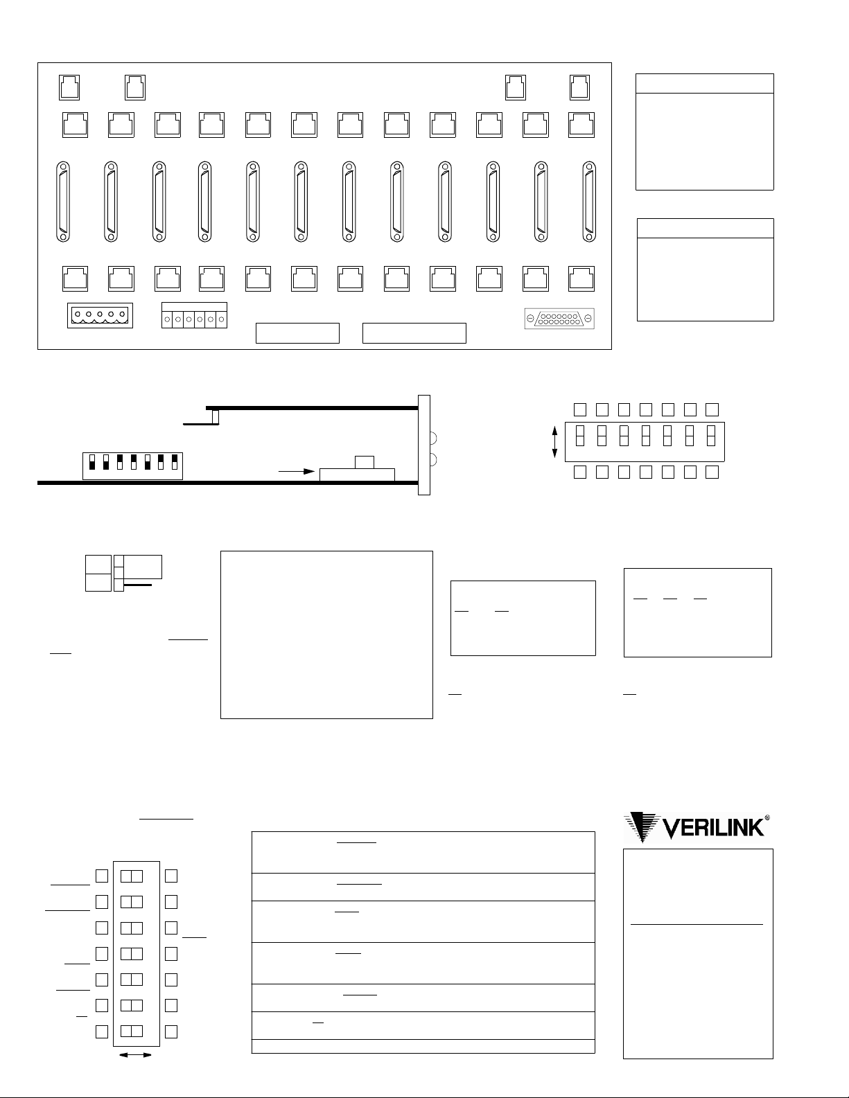
Verilink 1051 Chassis Rear View
( B )
NMS
OUT
T1 DTE
High Speed DTE
(V.35 version also available)
( A )
NMS
IN
( A )
NMS
OUT
Chassis Connections
Pin T1 DTE T1 NET
1 Data O u t Data I n
123456789101112
2 Data O u t Data I n
3 Not used Not used
4 Data I n D a t a O ut
5 Data I n D a t a O ut
6 Not used No t us e d
7, 8 Signal Gnd Signal Gnd
12
11 10 9 8 7 6 5 4 3 2 1
Pin NMS In NMS Out
1 Not Used Not Used
T1 NET
123456789101112
2 Signal Gnd Signal Gnd
3 Data O ut Data O ut
4 Data I n Not Used
5 Signal Gnd Signal Gnd
6 Not Used Not Used
TB1 TB2
TB1 TB2
ENET
Circuit Board View
Switch S3
Black squares indicate direction
of factory default switch settings
Alarm Relay
7654321
Alarm Relay
NO
NC
This three-pin jumper straps the
ACO alarm contact. Position jumper over pi ns 1 and 2 for normally
open operation (closes on alarm) or
over pins 2 and 3 for normally
closed operation (opens on alarm) .
1
2
3
For futu re reference, a ll D IP sw itches
are provided with upper and lower
boxes to check according to the particular user selectio n. Factory default
settings are shown underlined
.
Switc h S2 (front pane l)
Keep Alive
All Ones
Keep Alive
Unframed
Test Mode
BERT
Test Code
B8ZS
Test Pattern
Framed
Zeros
15
Reserved
7654321
RightLeft
Keep Alive
Loop Back
Keep Alive
Framed
Test Mode
Clear
Test Code
AMI
Test Pattern
Unframed
Zeros
175
Reserved
Optional Alarm Card
2100
front
Fact ory set -
do not c hange
TXKX
panel
Network LBO: Sets the output
signal level of transmitted data.
Optional Alarm Card
The optional ACO/ alarm card monitors the
The telco should provide the
proper setting. If unsure of the
exact setting, set to 0 dB.
alarm indicators for an alarm active or an
alarm clear condition and provides closure
contact points on the rear panel. The corresponding front panel LED lights when an
alarm condition is detected on the four different conditions shown below.
S3-1 S3- 2 L BO Level
Dn 0 dB
Dn
Dn Up -7.5 dB
Up Dn - 1 5.0 dB
Up Up - 2 2.5 dB
1) Network AIS (all ones)
2) Network LO S (all zeros)
3) Network BPVs
4) DTE ones densi ty
Switch S2 Desc rip tion
S3-6 Line Code
Up
: Line code transparent
Dn: DTE AMI –> NET B8ZS
7 Keep Alive: All Ones sends a consecuti v e sequ ence of al l ones back t o
the networ k. Loopback sends any signal coming from the network
back to the network.
6 Keep Alive: Unframed
transmits the Keep Alive signal without
framing. Framed adds framing information to the Keep Alive signal.
5 Tes t Mode: Clear
allows network access via test j acks to run bit error
tests (affects network test only). BERT allows the CSU to send a bit
error rate test pattern after the set signal (LOOP) is sent.
4 Tes t Code: B8ZS
allows the CS U to be transparent to a B8ZS code
coming from the network and sets the test signals to B8ZS. AMI shows
a BPV error for each event.
3 Test Pattern: Framed
indicates that the test signals (Set, Reset, and
BERT) are framed. ‘Unframed’ indicates the test signals are unframed.
2 Zeros: 15
allows 15 successive zeros from the DTE before the Keep
Alive mode is activated. 175 allows 175 zeros before activation.
1 Reserved.
Dn Up
Switch S3
7654321
DTE LBO: The tr ansmit o utput
level is selectable according to
the cable length from the CSU
DTE port to the T1 equipment.
S3-3 S3-4 S3-5 Distance
Up Dn 0'-133'
Up
Dn Dn Up 134'-266'
Up Dn Up 267'-399'
Dn Up Up 400'-533'
Up Up Up 534'-655'
S3-7 During Remote Loop
Up
:AIS to DTE
Dn: Network data to DTE
950 Explorer Blvd .
Huntsville, AL 35806
800 -926-0085
Product Technica l Sup port
(8 a.m. to 5 p. m . C en tral)
800 -285-2755 or
256 -327-2255
E-mail:
support@verilink.com
Online:
www.verilink.com
 Loading...