

Page 1

PRISM 2100
T1
CSU
®
TRANSPORT
34-00187
th
Edition
6
i
Page 2

Copyright
©1997 TxPORT. All rights reserved. No part of this publication may be reproduced, transmitted, transcribed,
stored in a retrieval system, or translated into any language in any form by any means without the written permission of TxPORT.
Reorder # 34-00187
th
Edition, March 1997
6
TxPORT shall not be liable for e rrors co ntained here in or for inci dental or co nsequent ial da mages in conne c-
tion with the furnishing, performance, or use of this material. TxPORT reserves the right to revise this publication from tim e to time and make changes in content without obligation to notify any person of such revision
changes.
Contents of this publication may be preliminary and/or may be changed at any time without notice and shall
not be regarded as a warranty.
Documentation Disclaimer
TxPORT makes no representation or warranties of any kind whatsoever with respect to the contents hereof
and specifically disclaims any implied warranties of merchantability or fitness for any particular purpose.
ii
Page 3

Table of Contents
General 1-1
Introduction 1-1
Features 1-1
Specifications 1-2
Network Interface 1-2
Equipment Interface 1-2
Diagnostics 1-2
Alarms 1-2
Power 1-2
Mechanical 1-2
Environmen t al 1-2
Industry Listings 1-2
FCC Requirements 1-2
Canadian Emissions Requirements 1-3
Warranty 1-3
Ordering Numbers 1-3
TxPORT Customer Service 1-4
Technical Support 1-4
Returns/RMA 1-4
Installation 2-1
Introduction 2-1
Safety Summary 2-1
Unpacking and Inspection 2-1
Supplied Materials 2-1
Mounting 2-1
Standalone Unit 2-1
Chassis Assembly 2-2
Unit Configuration 2-2
Configuration Switch S2 2-2
Sealing Current 2-2
Zero Suppression 2-2
Test Pattern 2 -2
Line Coding 2-2
Test Mode 2-2
Keep Alive 2-3
Configuration Switch S3 2-3
Network LBO 2-3
DSX Level 2-3
Line Code 2-3
Remote Loop 2-3
ACO/Alarm Card (Optional) 2-3
DTE Connection 2-4
DB-15 Connec tion 2-4
Network Connection 2-6
Alarm Connection (Optional) 2-6
Standalone Unit 2-6
Chassis Unit 2-6
Power Connection 2-7
Standalone Unit 2-7
Chassis Unit 2-7
Redundant Power Source 2-7
Single Power Source 2-7
Dual Power Source 2-7
Operation 3-1
Introduction 3-1
Front Panel Descriptions 3-1
General Status Indicators 3-1
Alarm Controls and Indicators 3-1
Test Controls and Indicators 3-1
Front Panel Testing 3-2
Test Switch 3-2
Test Access Jacks 3-2
NET 3-2
MON 3-2
DTE 3-2
iii
Page 4

iv
Page 5
1. General
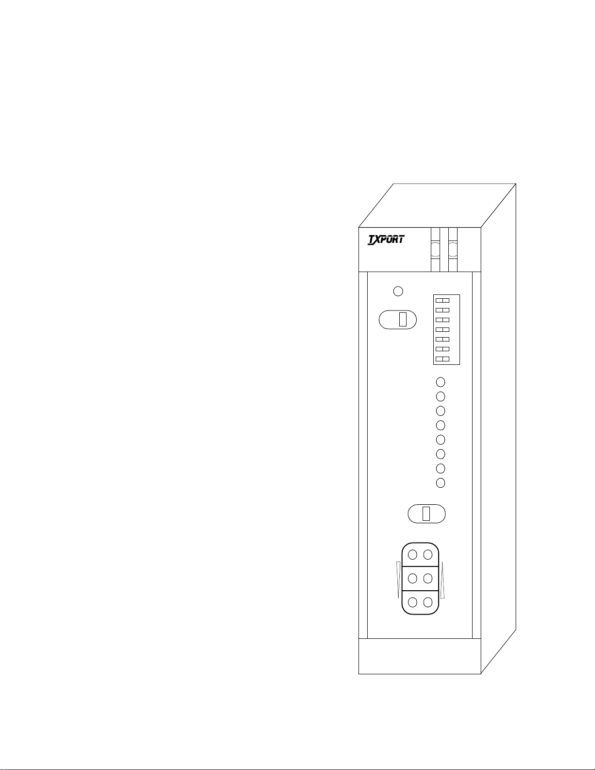
Figure 1-1 TxPORT 2100 CSU
Introduction
TxPORT’s 2100 CSU (channel service unit) is an advanced
frame transparent unit providing an interface between the
customer premises equipment (CPE) and the carrier T1
facilities. The unit is compatible with all T1 carrier transmission equipment and is designed to comply with all
industry standard CSU specifications. The 2100 CSU is
responsible for providing the proper electrical interface to
the T1 circuit and for shaping and regenerating the 1.544
Mbps signal.
The CSU works with any T1 line format and is line code
transparent to unframed, D4, and ESF framing formats.
Optionally, the CSU provides AMI /B8ZS conversion from
the DTE to the facility and B8ZS/AMI conversion from the
facility to the DTE. The unit monitors transmission for bipolar violations and maintains the pulse density of the
transmitted signal.
The CSU’s front panel has features which aid in quick fault
isolation. Eleven LED indicators display status, alarm, and
test conditions. A DIP switch allows for the quick configuration of operation and test parameters. Test jacks allow
bridged monitoring of th e passed si gnal and sign al insertion
toward the network or the DTE. A test switch activates local
and remote loops and controls the internal BERT generator
and comparator.
Power options for the CSU include line or local -24/-48
VDC power. Sealing current can be provided for dry spans.
Network and DTE connections are made through RJ-48C
jacks.
The CSU is available as a stand - alone unit or for use in a
multi -u nit chassis holding up to 12 CSUs. The chassis can
consolidate the CSU requirements of an entire network
node. Power supplies are available from TxPORT to meet
any requirement, including full redundancy.
• Selectable alarms with alarm indicators and optional alarm
relay contacts
• Selectable facility ALBO levels and DTE DSX levels
• Selectable sealing current source
• Line or local -48 VDC powering
2100
CSU
ACO SW
FAR
®
ACO
BPV
LOS
AIS
LOOP
DENSITY
SET
RESET
ERR
S2
7654321
LOC
TRANSPORT
Features
• Available as a stand-alone unit or a nest mounted unit
• Transparent to framing; supports ESF or D4 framing
• AMI or B8ZS line coding; B8ZS transparency
• Front panel test access jacks and test switch
• Complete diagnostic capabilities including loopbacks and
built-in BERT
FRM
NET
MON
TO
DTE
TO
NET
MON
FRM
DTE
General 1-12100 CSU
Page 6

Specifications
Network Interface
Line Rate: 1.544 Mbps, ±50 ppm for internal
clock, ±200 bps in through mode
Line Framing: D4 or ESF (transparent)
Line Code: AMI or B8ZS
Input Signal: DS1, 0 to -30 dB ALBO
Connection: RJ-48C jack, 100 Ω (± 5%)
Output Signal: 3.0 V (±15%) base-peak into 100 Ω
Line Build Out: 0, -7.5, -15, and -22.5 dB attenuation
Line Protection: 1000 V lightning, fused input/output
Sealing Current: 14 mA, switch selectable, 3500 Ω in
series with -48 VDC
Keep Alive: Line loopback or all ones (framed or
unframed)
Jitter Control: per TR62411 and T1.403
Pulse Density: 15 or 175 zeros
Equipment Interface
Line Rate: 1.544 Mbps, ± 50 ppm for internal
clock, ± 200 bps in through mode
Line Framing: D4 or ESF (transparent)
Line Code: AMI or B8ZS
Input Signal: DSX1 to - 6 dB
Connection: RJ-48C jack, 100 Ω (± 5%)
Output Signal: Selectable DSX1 level from 0 to 655
feet in six incremental levels
Line Protection: 1000 V lightning
Diagnostics
Loopbacks: Line loopback on network and DTE
interface
Network BERT: 1 in 8 (B8ZS), 3 in 24 (AMI), Clear,
selectable framed or unframed pattern
Alarms
Network Activation:BPVs, all zeros, AIS
DTE Activation: Low density (>15 or > 175 zeros)
Reporting: Front panel LEDs and alarm contacts
Contact Ratings: UL 120 mA @ 110 VAC or 110 VDC
Connection: Terminal strip
Power
Line Power: 60 or 140 mA, 33 V max
Local Power: 19 VDC to 60 VDC, 4.3 W, 15 BTU
Connection: Terminal strip
Mechanical
Mounting: desktop, wall, horizontal rack,
vertical rack
Dimensions: 1.72" W, 6.8" H, 10.5" D
Weight: 2 lbs.
Environmental
Operating Temp: 0° to 50° C(32° to 122°F)
Storage Temp: -20° to 85° C(-4° to 185°F)
Humidity: 95% max (non-condensing)
Industry Listings
FCC Compliance: Part 15 Subpart B, Class A
FCC Part 68 Reg: FXKUSA-74937-DE-N
UL Approved: E 110448
CSA Certified: LR 98859
DOC/CSO3: 1653 5331 A
FCC Requirements
WARNING: Changes or modifications
!
to this unit not expressly appr oved by the
party responsible for compliance could void
the user’ s authority to o perate the equipment.
This device complies with Part 15 of the FCC rules. Operation is subject to the following two conditions:
• This device may not cause harmful interference.
• This device must accept any interference received, including
interference that may cause undesired operation.
This equipment has been tested and found to comply with
the limits for a Class A digital device, pursu ant to Part 15 o f
FCC Rules. These limits are designed to provide reasonable
protection against harmful interference when the equipment
is operated in a commercial environment. This equipment
generates, uses, and can radiate radio frequency energy and
if not installed and used in accordance with the instruction
manual, may cause harmful interference to radio communications. Operation of this equipment in a resid ential area is
likely to cause harmful interference. The user will be
required to correct the interference at his own expense.
Notice to Users of 1.544 Mbps Service: The following
instructions are provided to ensure compliance with FCC
Rules, Part 68:
1. All direct connections to T1 lines must be made using
standard plugs and jacks.
2. Before connecting yo ur unit, you must inform the local
telephone company of the following information:
Port ID: SS-650810-A-NF
REN/SOC (Service Order Code): 6.0 N
1-2 General
2100 CSU
Page 7

FIC (Facility Interface Code):
04DU9-BN
04DU9-DN
04DU9-IZN
04DU9-IKN
04DU9-ISN
USOC jack: RJ-48C
RJ-48H
3. If the unit appears to be malfunctioning, it should be disconnected from the telephone lines until you learn
whether the source of trouble is your equipment or the
telephone line. If your equipment needs repair, it should
not be reconnected until it is repaired.
4. The unit has been designed to prevent harm to the T1
network. If the telephone company finds that the equipment is exceeding tolerable parameters, they can
temporarily disconnect service. In this case, the telephone company will give you advance notice, if possible.
5. Under FCC rules, no customer is authorized to repair this
equipment. This restriction applies regardle ss of whether
the equipment is in or out of warranty.
6. If the telephone company alters their equipment in a
manner that will affect the use of this device, they must
give you advance warning so that you can have the
opportunity for uninterrupted service. You will be
advised of your right to file a complaint with the FC C.
7. The attached affida vit must be completed by the installer.
8. In the event of equipment malfunctio n, all repairs shoul d
be performed by our company or an authorized agent. It
is the responsibility of users requiring service to report
the need for service to our company or to one of our
authorized agents.
Canadian Emissions
Warranty
TxPORT warrants each unit against defects in material and
workmanship for a period of five years from the date the
unit was shipped to the customer. If the unit malfunctions at
any time during the warranty period, TxPORT will repair, or
at TxPORT’s option, replace the unit free of charge.
The remedies listed herein are the user’s sole and exclusive
remedies. TxPORT shall not be liable for any indirect, direct, incidental or consequential damages. The owner must
return the unit to the factory, shipping prepaid and packaged
to the best commercial standard for electronic equipment.
TxPORT will pay shipping charges for delivery on return.
The customer is responsible for mode and cost of shipment
to TxPORT. This warranty does not apply if the unit has
been damaged by accident, misuse or as a result of service
or modification by other than TxPORT personnel.
When returning the unit for warranty work, a Return Material Authorization (RMA) number must be obtained from customer service at the address/phone number given below.
When calling TxPORT to obtain a Return Material Authorization number or to arrange service, please have the following information available:
• Model number(s) and serial number(s) for the unit(s).
• Reason for return and symptoms of problem.
• Warranty status (if known).
• Purc hase order number to c over charges for out -of-warranty
items.
• Name and phone number of person we can contact if we
have questions about the unit(s).
• Mode of shipment required (second day air is the normal
mode of shipment for all returned material unless otherwise
specified).
As soon as TxPORT has the above information, the RMA
that must accompany the item(s) returned can be issued.
Requirements
This digital apparatus does not exceed the Class A limits for
radio noise emissions from digital apparatus set out in the
Radio Interference Regulations of the Canadian Department
of Communications.
End users should use existing 48-VDC battery
sources or a CSA certified power supply.
Le présent appareil numérique n’émet pas de bruits
radioélectriques dépassant les limites applicables aux appareils numériques (de la class A) prescrites dans le Règlement
sur le brouillage radioélectrique édicté par le ministère des
Communications du Canada.
Ordering Numbers
The part numbers for the stand- alone unit and the modular
chassis unit are shown in Table 1-A on page 1-4 :
The unit is shipped from the factory with the 2100 CSU
reference manual. Refer to Table 2-B on page 1 -4 for the
optional equi pment part numbers.
General 1-32100 CSU
Page 8

Table 1-A 2100 CSU Part Numbers
Part Number Description
BCD
F-2100-100-1
F-2100-101-11
2100 D4 CSU stand - alone unit
B
Special option
1
Standard unit
2
Ones-density disable
C
Backplane option
1
RJ-48C NET / RJ-48C DTE
2
RJ-48C NET / DB-15 DTE
3
DB-15 NET / DB-15 DTE
D
ACO (alarm cut off) option
0
Without A C O
1
With ACO
C
0
2100 D4 CSU module (chassis)
C
Panel / ACO option
0
1051 chassis without ACO
1
1051 chassis with ACO
2
K - type without ACO
3
K - type with ACO
The following accessories may also be needed for the installation and operation of the 2100 CSU.
Table 2-B Optional Equipment
Part Numb er Description
9 - 1544N- 075 --X
9 - 1544N-07 6 - -X
9-1001-006--X 8-pin jack to 15-pin adapte r w/ screw
9-1001-009--010 8-pin to 8-pin twisted pai r
9-1001-011--025
9-1001-012--025
9-1001-036--010
9-1001-037--010
9-1001-048-1 Y male adapter/cable (splits EM8000
33-00085
33-00086
9-2000-036--1 Stand-alone to rack mount conversion
F-1051-000--111
F-1051-000--112
9-2000-001--1
9-2000-001--2
9-2000-002--1
9-2000-002--2
F-1040-000--111
F-1040-000--112
F-1200-000--11 1200 power supply with redundant
9-8000-001-1
9-8000-001-2
Va riable X in the part number as follows: 1 = male, 2 = female.
8-pin jack to 15-pin adapter w/ post
8-pin jack to 15-pin adapter w/ nuts
50-pin male-male twisted pair
50-pin male-female twisted pair
50-pin to 8-pin modular (DTE)
50-pin to 8-pin modular (NET)
In/Out), DB-25 to two 6-pin NMS ports
Bantam to bantam test cord - red
Bantam to bantam test cord - black
module with DB-25 to 6-pin adapter
1051-1 chassis (RJ-48H)
1051-2 chassis (RJ-48C)
19" single unit rack mount adapter
19" dual rack mount adapter
23" single unit rack mount adapter
23" dual rack mount adapter
Power shelf with single 48 VDC, 2 A supply
Shelf with redundant 48 VDC, 2 A supply
-48 VDC, 5 A with fuse panel
EM8000 with manual on 3-1/2 inch disk
(DOS and UNIX version, respectively)
TxPORT Customer Service
TxPORT office hours are Monday through Friday from 8
a.m. to 5 p.m. Central Time. For general, sales, and marketing information, contact TxPORT at:
Toll Free: 888-4TxPORT
Toll Free: 800-926-0085
Local: 205-772-3770
International: 205-772-3770
e-mail: info@txport.com
Technical Support
Technical supprt is available 24 hours a day, seven days a
week. You may contact a support representative by telephone or e-mail.
Toll Free: 1-800-285-2755
Local: 205-772-3770
International: 205-772-3770
e-mail: support@txport.com
Returns/RMA
If for any reason you need to return a TxPORT unit, you
must have a Return Material Authorization (RMA) number
marked on the shipping package. You may obtain an RMA
number from customer service at 888-4TxPORT; 8000-9260085, ext. 2227; or for local or international customers 205772-3770.
When calling TxPORT for an RMA; please have the following information available:
• Model number and serial number for each unit.
• Reason for return and symptoms of the problem.
• Warranty status (if known).
• Purc hase order number to cover charges for out-of-warranty
items.
• Name and telephone number of a person we can contact if
we have questions about the unit(s).
• Mode of shipment required (second-day air is the normal
mode of shipment for all returned material unless otherwise
specified).
Units being returned to TxPORT should be sent to the following address:
TxPORT, Inc.
127 Jetplex Circle
Madison, Alabama 35758
1-4 General
2100 CSU
Page 9

2. Installation
Introduction
This chapter contains information and instructions required to
prepare the TxPORt 2100 CSU for use, Included are initial
inspection procedures, mounting instructions, configuration
guidelines, connection instructions, and powering information.
Throughout this manual, all factory default settings are
underlined.
Safety Summary
This manual contains information and warnings that must be
followed to ensure safe operation and to retain the equipment in a safe condition.
The WARNING sign denotes a hazard
to the operator. It calls attention to a
procedure or practice which if not correct performed or adhered t o, cou l d r esu l t in in ju r y or
loss of life. Do not proceed beyond a WARNING sign until the indicated conditions are
fully understood and met.
Follow proper ESD (electrostatic discharge) procedures while handling the circuit boards.
Unpacking and Inspection
Supplied Materials
The TxPORT 2100 CSU is shipped from the factory with the
2100 CSU reference guide.
The following additional material may be required for the
installation and operation of the un it:
• -48 VDC power source
• Network and DTE interface cables
• Bantam test cables
• 2 0-gauge stranded wire (or sim ilar) for DC power and alarm
connection
For specific applications, additional adapters and cables may
be required. The interface requirements of any application
may be met by using the appropriate cable. Standard cables
and ordering numbers are listed in Optional Equipment on
page 1-4. Contact TxPORT for any needed assistance in
cable selection.
Mounting
The TxPORT 2100 CSU is a modular unit that plugs into
either single unit housing or into a chassis that holds up to
12 CSUs. Single units are designed for standalone desktop
use, wall mounting, or rack mounting (in either a vertical or
horizontal orientation). The CSU utilizes an interchangeable front panel to accommodate the chassis card cage.
This unit is carefully packaged to prevent damage in shipment. Upon receipt, inspect the shipping container for
damage. If the shipping container or cushioning material is
damaged, notify the carrier immediately and make a notation on the delivery receipt that the container was damaged
(if possible, obtain the signature and name of the person
making delivery). Retain the packaging material until the
contents of the shipment have been checked for completeness and the instrument ha been checked both mechanically
and electrically.
If the contents of the shipment are incomplete or, if there is
mechanical damage or defect, notify TxPORT. If the shipping container is also damaged, or the cushioning material
shows signs of stress, notify the carrier of the damage as
well as TxPORT. Keep the shipping materials for carrier’s
inspection. TxPORT will arrange for repair or replacement
without waiting for claim settlement.
Standalone Unit
To access the circuit boards and configuration switches, perform the following steps:
1. Remove the front panel cover by opening the front panel
access door and gently spreading the plastic from the
middle using both hands.
2. Pull the two sides o f the plastic cover from the middle
outwards until the four stops are clear of the front panel.
Pull the cover off the front panel.
3. Remove the two Phillips-head screws from the front
panel and pull the front panel and circuit boards out of
the housing. Observe the proper electrostatic discharge
procedures while handling the circuit boards.
The standalone unit may be used in a chassis installation
with the following modifications:
1. Remove the housing as described in the procedure above
and then remove the four screws holding the front panel
to the circuit boards
Installation 2-12100 CSU
Page 10

Alarm Relay
Optional Alarm Card
Switch S3
12 76543
Figure 2- 1 Bottom-Edge View of the 2100 CSU
2. Replace the standalone front panel with a front panel
module. The unit can now slid e into one of the 12 C SU
slots on the chassis fron t.
Chassis Assembly
Up to 12 modular units may be inserted into a chassis and
the chassis may be installed in a 19-inch or 23-inch rack
using four screws. Connections are made from the rear of
the chassis. Refer to Figure 2-6 on page 2-5.
Unit Configuration
The TxPORT 2100 CSU is hardware configured using two
DIP switches and a jumper located on the side of the circuit
boards. These are shown in Figure 2-1 except for Switch S2
which is located on the front panel (see Figure 2- 2). The
numbering system used for each switch position is as follows: Position 2 of Switch S3 is referred to as Switch S3-2,
and so on.
Before installation, verify each configuration switch setting.
Differences in the switch settings between the chassismount and standalone units are shown on their respective
configuration guides.
Configuration Switch S2
Front panel Switch S2 (Figure 2-2) is used to set the con figuration parameters listed in the following paragraphs.
Keep Alive - All Ones
Keep Alive - Unframed
Test Mode - BERT
Line Mode - B8ZS
Test Pattern - Framed
Zeros - 15
Sealing Current - Off
Left Right
Figure 2-2 Switch S2
Sealing Current
Position S2-1 is used to apply a sealing cu rrent of 20 mA to
the network interface for applications where the telco provides a dry (no power interface and sealing current is
needed. For most applications (where the telco provides line
power or where sealing current is not required), this switch
should be left in the Off position.
Keep Alive - Loopback
Keep Alive - Framed
Test Mode - Clear
Line Mode - AMI
Test Pattern - Unframed
Zeros - 175
Sealing Current - On
12 76543
Up
Down
Switch S4 is set
at the factory—
do not change.
Switch S4
KX TX
Sealing current is any low-level current passing through a
splice, joint, or wire-wrap connection. It seals the joints on a
span line. The action of the current flow prevents the joint
from becoming a source of high impedance.
Prior to divestiture, th e CSUs were owned and powered by
the telephone company, ensuring sealing current on all joints
up to the CSU. Since divestiture, the telephone company
may sometimes loop the power back at the last repeater or at
the network interface. This removes power from the final
section, which in turn removes sealing current from those
joints. The dry spans can cause mechanical contacts to eventually fail. Providing sealing current to a span reduces this
corrosion.
Left: sealing current is Off.Right: sealing current is On.
WARNING: Enabling sealing current
with telco line power present could dam-
age the unit and/or cause improper operation.
Zero Suppression
Position S2-2 implements ones-density insertion after the
preset number of zeros has been received from the DTE and
the Keep Alive mode is activated.
Left: 15 zeros Right: 175 zeros
Test Pattern
Position S2-3 sets the framing of the SET, RESET, and
BERT test signals.
Left: Framed Right Unframed
Line Coding
Position S2-4 sets the network line coding. If set to AMI, the
unit indicates a BPV error for each event. The B8ZS code
coming from the network and sets the test signals to B8ZS.
Left: B8ZS Right: AMI
Test Mode
Position S2-5 either sets or clears the test pattern. The BERT
position allows the CSU to send a BERT pattern after the set
signal (LOOP) is sent. Clear passes the traffic from the DTE
through the network and allows network access via test
jacks to run bit error tests (affects network tests only).
Left: BERT Right: Clear
2-2 Installation
2100 CSU
Page 11

Keep Alive
Positions S2-6 and S2-7 are used to select the action that
occurs upon loss of DTE signal, when the unit switches to
the Keep Alive mode on the network line. The choices are
shown in Table 2-C.
Table 2-C Keep Alive Settings
Table 2-E DSX Level
DTE LBO S3-3 S3-4 S3-5
267-399 ft Up Down Up
400-533 ft Down Up Up
534-655 ft Up Up Up
Function S2-6 S2-7
Keep Alive is unfram ed all ones Left Left
Keep Alive is framed all ones Left Right
The Keep Alive signal is the acti-
vation of the line loopback.
Right Left
Right Right
Configuration Switch S3
Switch S3 is used to set the configuratio n parameters listed
in the following paragraphs.
NET LBO
NET LBO
DTE Level
DTE Level
DTE Level
Line Code
Remote Loop
Up
12 76543
Figure 2-3 Switch S3
Network LBO
Positions S3-1 and S3-2 set the output signal level to the
transmit data (TXD) from the CSU to the network to the
proper line build out. These values are shown in Table 2-D.
The output level is factory set at 0 dB . It may be attenuated
by 7.5 dB, -15 dB, or -22.5 dB if operating conditions
require that it be changed. The telco should provide the
proper seting to the user. If unsure of the exact setting, then
leave it at 0 dB.
Table 2-D Network Line Build Out
Down
Line Code
Position S3-6 is used to provide AMI/B8ZS conversion from
the DTE to the facility and B8ZS/AMI conversion from the
facility to the DTE or set the line code to be transparent.
Up: Transparent Down: Conversion
Remote Loop
Position S3-7 is used to select the signal sent to the DTE
during a remote loop.
Up
: AIS to DTE Down:Network data to DTE
ACO/Alarm Card (Optional)
The optional; ACO/alarm card monitors the alarm indicators for an alarm active or an alarm clear condition and
provides closure contact points on the rear panel. The corresponding front panel LED lights when an alarm condition is
detected on four different conditions:
• Network AIS (all ones)
• Network LOS (all zeros)
•Network BPVs
• DTE ones density)
The alarm card circuitry scans the status (on or off) of the
alarm indicators ten times a second (100-ms windows). The
card declares an alarm if one or more indicators are on for
100 consecutive 0.1-second samplings (10 seconds). When
this happens, the red Status indicator turns on until no alarm
conditions are detected for more than 100 consecutive 0.1second samplings (another 10 seconds).
Network LBO S3-1 S3-2
0 dB Down Down
-7.5 dB Down Up
-15.0 dB Up Down
-22.5 dB Up Up
DSX Level
Positions S3-3, S3-4, and S3-5 set the DTE line interface
DSX level to one of the values shown in Table 2-E. The setting should match the cable length from the C SU DTE port
to the attached equipment (cross-connect).
Table 2-E DSX Level
DTE LBO S3-3 S3-4 S3-5
0-133 ft Up Up Down
134-266 ft Down Down Up
Installation 2-32100 CSU
Page 12

DTE Connection
The DTE interface of the CSU is a DSX interface. The DTE
output level should be set as described in DSX Level on
page 2- 3. The DTE physical interface for both the standalone unit (Figure 2 -4) and the chassis unit (Figure 2- 5 and
Figure 2- 6) is a standard RJ-48C, 8-pin modular jack with
the pinout shown in Table 2-F.
Table 2-F DTE Interface Pinout
Pin DTE Interface
1 Data Out
2 Data Out
3Not Used
4 Data In
5 Data In
6Not Used
7, 8 Chassis Ground
DB-15 Connection
DB-15 connectors are optional for the DTE and network
interfaces. Refer to Optional Equipment on page 1-4 for
ordering information. The DB-15 pinout is shown in Table
2-G.
Table 2-G DB-15 DTE and Network Interface
Pinouts
Pin DTE NET
1 Data In Data Out
2 Frame Ground Frame Groun d
3 Data Out Data In
4 Frame Ground Frame Groun d
9 Data In Data Out
11 Data Out Data In
8
1
DTE
1+V
2GND
3-V
4FRM GND
5ALM
6ALM COM
1
8
1
6
DB-15
(optional)
DB-15
(optional)
NET
Figure 2-4 2100 CSU Standalone Rear Panel
2-4 Installation
2100 CSU
Page 13

Unit 1 Unit 2 Unit 3 Unit 4 Unit 5 Unit 6 Unit 7 Unit 8 Unit 9 Unit 10 Unit 11 Unit 12
T1
DTE
12
14
High
Speed
DTE
12
25
T1
NET
12
TB1 - 23451
( B )
NMS
16
81
1
13
81
IN
DTE
High
Speed
DTE
NET
Line Chassis Mounting Hardw are
Rack and19" or 23" Multiple
Figure 2-5 Model 1051-2 Chassis, Front View
( B )
NMS
OUT
T1
11
11
T1
11
T1
DTE
10
High
Speed
DTE
10
T1
NET
10
Redundant
Power
Board
T1
DTE
9
High
Speed
DTE
9
T1
NET
9
TB2 - 23456
DTE
High
Speed
DTE
NET
1
T1
8
8
T1
8
T1
DTE
7
High
Speed
DTE
7
T1
NET
7
1 - EXT CLK
2 - EXT CLK
3 - ALARM RING
T1
DTE
6
High
Speed
DTE
6
T1
NET
6
TB1
4 - ALARM TIP
5 - SIG GND
T1
DTE
5
High
Speed
DTE
5
T1
NET
5
T1
DTE
4
High
Speed
DTE
4
T1
NET
4
1 - +48V RTN (B)
2 - FRAME GND
3 - -48V IN (B)
TB2
T1
DTE
3
High
Speed
DTE
3
T1
NET
3
4 - -48V IN (A)
5 - SIG GND
6 - +48V RTN (A)
( A )
NMS
IN
T1
DTE
2
High
Speed
DTE
2
T1
NET
2
( A )
NMS
OUT
T1
DTE
1
High
Speed
DTE
1
T1
NET
1
ENET
Figure 2-6 Model 1051-2 Chassis, Rear View
Installation 2-52100 CSU
Page 14

Network Conn ectio n
Figure 2-7 Alarm Relay Jumpers and Strap
NO
NC
The network side of the CSU is referred to as the network
interface. This interface is located on the contains an ALBO
to allow the unit to be located a substantial distance away
from the telco network interface (receive signal level down
to -30 dB).
The network interface line build out (LBO) levels should be
adjusted as in Table 2-D on page 2 -3. The maximum suggested cable lengths for connection of the CSU to the
network are shown in Ta ble 2-H. Calculations are based on a
70°F cable temperature; a 0.083 µF capacitance; a 30-dB
loss; and a 100-Ω, non-loaded, twisted pair cable. PIC refers
to Plastic Insulated Cable.
Table 2-H Line Loss versus Cable Gauge
Cable Type Loss per 1000' Max Length
26-gauge PIC 6.8 dB 4,400 ft
24-gauge PIC 5.4 dB 5,500 ft
22-gauge PIC 4.2 dB 7,100 ft
19-gauge PIC 3.0 dB 10,000 ft
Standalone Unit
The connection for the standalone unit is made on pins 5 and
6 of the Alarm/Power connector as shown in Table 2-J.
Table 2-J Power and Alarm Connector Pinout
Pin Function
1 48 VDC Return
2 Signal Ground
3-48 VDC
4 Frame Grou nd
5 Alarm Contact
6 Alarm Common
Pin 5 is configured to operate in either a normally open
(NO) or normally closed (NC) mode as determined by the
setting of the alarm relay jum per shown in Figure 2-7. This
jumper is located on the circuit board.
The network physical interface for both the standalone unit
and chassis unit is a standard RJ-48C 8-pin modular jack
with the pino ut shown in Table 2-I.
Table 2-I Network Interface Pinout
Pin NET Interface
1 Data In
2 Data In
3 Not Used
4 Data Out
5 Data Out
6 Not Used
7, 8 Chassis Ground
In accordance with FCC rules, Part 68.218(b),
notify the telephone company before disconnecting the CSU.
Alarm Connection (Optional)
The standalone unit and the chassis modular unit provide
rear panel alarm relay contacts as an option. These dry (isolated) alarm contacts permit connection to a remote
indicating device.
The unit allows normally open (NO) or normally closed
(NC) alarm relay contacts. Using NO contacts, a nest of
CSUs and any other equipment may use a common bused
alarm line. Using a NC contact set allows a serial daisy
chain from unit to unit. Any unit going into alarm then
breaks the alarm loop.
NO and NC refer to the contact’s relationship to the common contact under a no alarms conditio n. Move the jumper
to NC for normally closed operation (opens on alarm) or to
NO for normally open operation (closes on alarm).
Make connections to the alarm contacts using 20-gauge
stranded (or similar) wire. The contacts are rated at 120 mA
AC or 120 mA DC.
Chassis Unit
Alarm conditions from all modules in the chassis are bused
together in parallel and are presented on a sin gle set of alarm
relay contacts which permit connection to a remote indicating device. When connected, pins 3 and 4 on terminal strip
TB1 operate in normally open mode. Refer to the 1051-2
Chassis Configuration Guide for further information.
All PRISM 3001 modules in a common chassis
must use the normally open contact mode.
Make connections to the alarm contacts using 20-gauge
stranded wire (or similar). The contacts are rated at 120 mA
AC or 120 mA DC.
2-6 Installation
2100 CSU
Page 15

Power Connection
The standalone unit and the modular chassis unit require a 19- to 60-VDC power supply capable of delivering 4.3 watts
per unit. Power supplies are available from TxPORT and are
listed in Optional Equipment on page 1-4.
Connect the ground lead before applying power to the unit.
Standalone Unit
The power source is connected to pins 1 and 3 of the Power
and Alarm terminal as shown in Table 2-J on page 2-6.
Connect a chassis ground lead (18- to 20-gauge is recommended) to the Frame Ground terminal (pin 4). Connect the
other end of this lead to an appropriate facility ground.
Often, the 48 DC return is also ground. In that case, both
return and ground leads should be connected to ground.
Connect the lead of the -48VDC source to the -V terminal
(18- to 20-gauge wire is recommended). Connect the return
lead of the 48-volt source to the +V terminal. When powered
up, the STATUS indicator on the front panel lights and the
unit goes through the normal LED sequencing.
Chassis Unit
the chassis is designed with two power buses. The A bus
feeds the odd slots while the B bus feeds the even slots.
Refer to Figure 2-6 on page 2 -5 for an illustration of the
1051-2 rear panel and to the appropriate 1051 chassis configuration guide for further information.
Three modes of powering the chassis are available:
Redundant Power Source
A redundant power board is factory installed on power connector TB2 which allows connection of two independent -48
VDC supplies operated in a redundant mode. All slots are
powered from the combi ned inpu t of t h e A and B power supplies. If either supply fails, the other powers the entire
chassis.
Single Power Source
Using a single power source is essentially th e same as the
redundant configuration with power supply B not operational. If the redundant power board is not used, the A bus
and the B bus must be connected together with a jumper.
Dual Power Source
When using a dual independent power supply, one -48 VDC
source feeds the A bus while another -48 VDC source feeds
the B bus.
Each 2100 CSU requires a 19- to 60- VD C pow er
supply capable of delivering 4.3 watts. Ensure
the proper fuse size is used. Refer to the 1040
Power Shelf configuration guide.
Installation 2-72100 CSU
Page 16

2-8 Installation
2100 CSU
Page 17

3. Operation
Figure 3-1 2100 CSU Front Panel
LOC
FAR
ACO SW
ACO
LOOP
BPV
LOS
AIS
DENSITY
SET
RESET
ERR
7654321
S2
FRM
NET
MON
TO
DTE
TO
NET
MON
FRM
DTE
3
2
4
1
5
6
8
7
9
10
11
12
13
2100
CSU
Introduction
This chapter contains the general operation instructions for
the TxPORT 2100 CSU. The unit is operated manually by
using the front panel controls and indicators (described in
this chapter) and configuration Switch S2 (described in the
Installation chapter).
Front Panel Descriptions
The 2100 CSU uses LED indicators to convey major alarm
conditions and looping status. The front panel contains 11
LED indicators, a test switch, and a set of bantam test jacks.
The following paragraphs describe these controls and indicators and are referenced to the illustration on this page.
General Status Indicators
1. STATUS: The CSU has two LED indicators on the
front panel bezel that are exposed whether the access
door is open or closed. These general status LEDs provide a quick check of the CSU’s operating condition
(Go or No Go).
If neither LED is lit, the unit is not powered. If the
green LED is lit, the unit is powered and functioning
normally. If the red LED is lit, there is a lin e fault wh ich
exceeds alarm thresholds or another type of unit failure.
The problem can be isolated by further examinat ion of
the other front panel LEDs as described below.
Alarm Controls and Indicators
2. ACO: This red LED lights whenever the alarm cut off
switch is in the right (On) position (when the alarm
relay contacts are disabled).
3. ACO SW: The alarm cut off switch controls the alarm
relay circuitry. If the switch is placed in the right On
position, this circuitry is deactivated. The left Off position enables the contacts to report alarm conditions.
4. BPV: This red LED lights (0.1 second minimum) for
each occurrence of bipolar violations from the network.
5. LOS: This red LED lights constantly when a loss of
signal condition is detected from the network.
6. AIS: This red alarm indication signal LED lights con-
stantly if an unframed all-ones condition is detected
from the network.
TRANSPORT
®
7. DENSITY: This red LED lights co nstantly if the ones
density from the equipment is less than 12 .5 percent or
if there is a loss of signal.
Test Controls and Indicators
8. LOOP: This yellow LED lights constantly when the
network interface is in a line loopback.
Operation 3-12100 CSU
Page 18

9. SET: This yellow LED flashes if the set code is trans-
Receive signal
from the DTE
Transmit signal
to the network
Transmit signal
to the DTE
Receive signal
from the network
Monitor signal
from the network
Monitor signal
from the DTE
Figure 3-3 Test Jacks
mitted. It lights constantly if the set code is received.
10. RESET: This yellow LED flashes if the reset co de is
transmitted. It lights constantly for five seconds if the
reset code is received.
11. ERR: This red LED lights 0.1 second if an error is
received during a network test.
12. Test Switch: This switch (FAR/ LOC) is used for local
testing. Refer to T est Switch below for more informa tion.
13. Test Access Jacks: These six bantam test jacks are
provided for access to the T1 line on the DTE side of
the CSU. Refer to Test Access Jacks below for more
information.
Front Panel Testing
The previous section gave a brief description of each front
panel control and LED indicator. This section explains the
front panel test functions. Testing may also be performed
using software control from the TxPORT EM8000 element
manager (refer to the EM8000 reference manual).
Test Switch
This switch is used for local testing. When in the Far posi tion (FAR), the unit sends five seconds of IBLC (in-band
loop codes), then switches to Clear Test or BERT When
transmitting IBLC or the t est pattern, the test LED blinks.
The ERR LED lights for 0.1 second when a bit error or sync
loss is detected.
When this switch is returned to the normal center positio n,
the unit sends five seconds of loop down code (100) and
then returns to its normal operating mode.
When the Test switch is in the local position (LOC), the unit
performs a bidirectional loopback as shown in the following
diagram and the LLB indicator lights.
Test Access Jacks
Six bantam test jacks are provided for access to the T1 line
on the DTE side of the CSU. Jacks allow transmit and
receive toward the network, toward the DTE, or monitoring
traffic between DTE and network. Jacks are customarily
used to inject and receive T1 signals using a T1 test set.
NET
The top two ports are used to insert into the line in both
directions. They break connection to the DTE and make
connection to the CSU in the direction of the network.
MON
The middle two ports are used for non-intrusive bridge
monitoring of the line in both directions. They monitor the
signals passing through the CSU (between the DTE and the
network).
DTE
The bottom two ports are used to drop the line. They break
connection to the CSU and make connection to the DTE.
3-2 Operation
Equipment Network
Figure 3-2 Local Loop
CSU
2100 CSU
Page 19

®
TRANSPORT
Document:
Date:
PRISM 2100 T1 CSU Reference Manual, 6th Edition, March 1997
September 30, 1997
Addendum
Sealing Current and Line
Power Are Not Applicable
The following no longer applies:
Page 1-1: The second sentence of the fourth paragraph of
the section Introduction
Selectable sealing current source under Design
Highlights
34-00187-A6.01
Page 1-2: Sealing Current under Network Interface of
Specifications
Line Power under Power of Specifications
Page 2-2: Figure 2-2 Switch S2, position 1 and section
Sealing Curre nt
 Loading...