

Page 1

TRANSPORT
®
®
USTOMERSERVICE
TRANSPORT
TxPORT
127 Jetplex Circle
Madison, Alabama 35758
C
T e le ph one Number : 800-926-0085 or
205-772-3770
Sales /Administration FAX: 205-772-3388
Customer Service Returns: 800-926-0085, ext. 227
Product Technical Support
Normal Hours:
8 a.m. to 5 p.m. Central Time, Monday – Friday
T e le ph one Number : 800-285-2755
205- 772-3770, ext. 255
or ext. 252 (manager)
Emergency Hours (Nights / Weekends / Holidays):
800- 285-2755
205-603-2194 (Manager)
P
RODUCTIVITY
S
200 CSU
210 CSU
R
EFERENCE
34-00196
1
ST
ERIES
M
E
DITION
ANUAL
1 16
Page 2
OPYRIGHT/LIABILITY
DTE
NET
Local Loopback
DTE
NET
AIS
Remote Loopback
C
© 1995 TxPORT, All rights reserved. No part o f this publica tion may be rep roduced,
transmitted, transcribed, stored in a retrieval system, or translated into any language in
any form by any means without the written permission of TxPORT.
Reorder # 34-00196
1st Edition, March 1995
TxPORT shall not be liable for errors contained herein or for incidental or consequential damages in connection with the furnishing, performance, or use of this material.
TxPORT reserves the right to revise this publication from time to time and make
changes in content without obligation to notify any person of such revision changes.
Contents of this publication may be pre liminary and/or may be c hanged at any time
without notice and shall not be regarded as a warranty.
The controls, indicators and test features are identical for both units except for the front
panel ‘FAR’ indicator, which is found only on the 200 CS U. Each unit uses LED in dicators to convey major alarm conditions and looping status. Loop s are initiated using
the network test switch.
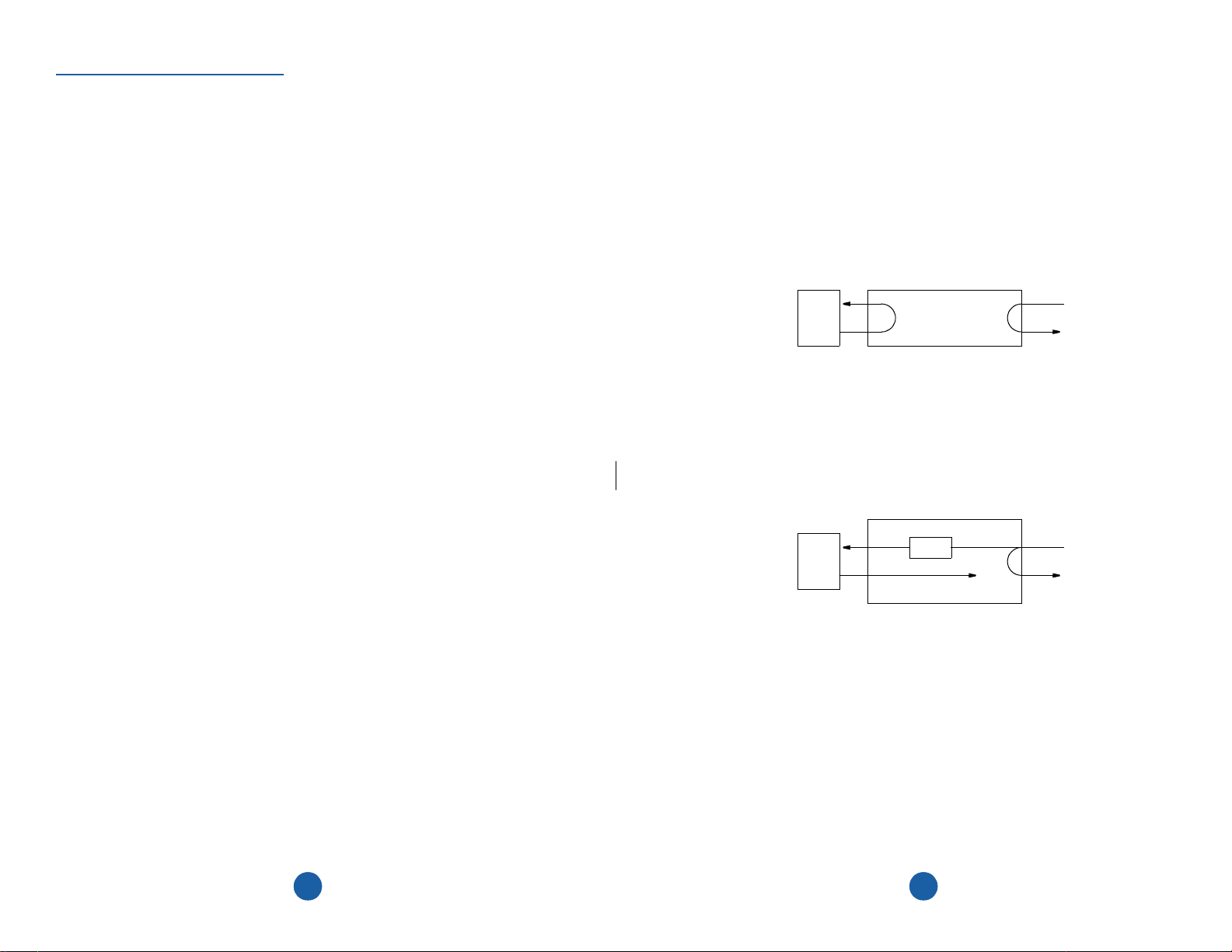
3.1 Testing
The front panel test switch is used for local testing. When placed in the local loop
mode (LOOP), the unit loops the signal from the customer equipment (DTE IN) back
to the customer equipment (DTE OUT). It also loops the received signal from the T1
facility (NET IN) back to the T1 facility (NET OUT). When moved back to ‘NORM’,
the local loopback is removed.
The unit can also be looped remotely by generating towards it a standard CSU line
loopback code (000 01 repeating for Š 5 se conds, framed or unframe d). Once looped,
the received signal from the T1 facility (NET IN) is regenerated and transmitted back
to the T1 facility (NET OUT). The unit can be unlooped remotely by generating
towards it a standard CSU line unloop code (001 repeating for Š 5 seconds, framed or
unframed).
Documentation Disclaimer
TxPORT makes no representation or warranties of any kind what soever with respect to
the contents hereof and specifically disclaims any implied warranties of merchantability or fitness for any particular purpose.
2
DIP switch S1-6 configures the unit to either generate an unframed all ones (AIS) signal to the DTE or to pass the received data from the network to the DTE. The 200 unit
responds to the facility data link (FDL) loop (PLB, 0000111011111111) and unloop
command messages (0011100011111111) .
15
Page 3
O
PERATION
T
ABLE OFCONTENTS
3.0 Introduction
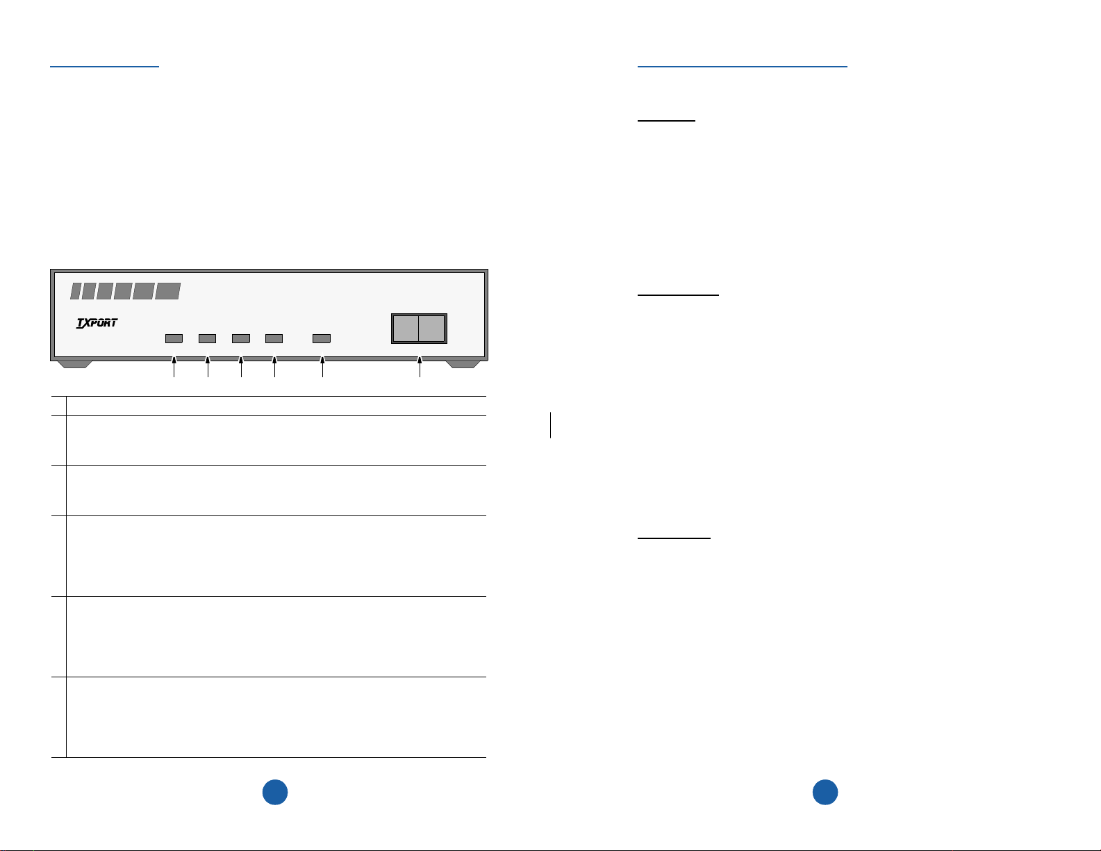
This chapter describ es the front panel operat ion and test features of the TxPORT 200
and 210 CSUs. Both units are controlled manually using a front panel test switch and
rear panel DIP switches (the DIP switches are discussed in the ‘Installation’ chapter).
The front panel switch and the LED indicators are described below.
200 CSU Front Panel
PRODUCTIVITY SERIES 200
®
TRANSPORT
CSU
POWER
1
DTE T1 Status:
2
of signal condition for Š 175 bit times from the DTE. The LED stays lit until the
unit detects Š 4 pulses in 32 bit times.
Network T1 Status:
3
loss of signal condition for Š 175 bit times from the network. The LED stays lit
until the unit detects Š 4 pulses in 32 bit times.
Far end T1 status
4
cuitry detects a yellow alarm signal from the far end terminal equipment. This condition occurs if the far end terminal is out of sync with the T1 signal from the
network. The format for a yellow alarm is bit 2 set to 0 in each DS0 (D4 mode) or
8 ones/8 zeros in the facility data link (ESF mode).
Loop:
5
switch is placed in the ‘LOOP’ position or the unit receives an inband loop code
for > 5 seconds, or (for the 200 only) the unit re ceives an FDL loop message (PLB
or LLB). The LED does not light if the test switch is placed in the ‘NORM’ position or if an inband or FDL unloop code is received for >5 seconds.
Te st Swi tch:
6
local loop mode (LOOP), the unit loops the signal from the customer equipment
(DTE IN) back to the customer equipment (DTE OUT). It also loops the received
signal from the T1 facility (NET IN) back to the T1 facility (NET OUT). When
moved back to ‘NORM’, the local loopback is removed.
: This green LED lights when power is applied to the unit.
This amber LED lights under the following conditions: the manual loop
PWR DTE NET LOOPFAR
This red LED lights if the internal alarm circuitry detects a loss
This red LED lights if the internal alarm circuitry detects a
(200 CSU only): This red LED lights if the internal alarm cir-
This 2-position switch is used for local testing. When placed in the
LOOP NORM
654321
General
Introduction ................................................................................... 4
Specifications ................................................................................ 5
FCC Requirements ........................................................................ 6
Warranty ........................................................................................ 7
Ordering Numbers .................................................... ..................... 8
Installation
Introduction ................................................................................... 9
Supplied Materials ........................................................................ 9
Unit Configuration ........................................................................ 9
Configuration Switch S1 ........................................................ 10
Configuration Switch S2 ........................................................ 11
Connections ................................................................................... 12
DTE and Network Connections ............................................. 13
Power Connection .................................................................. 13
Operation
Introduction ................................................................................... 14
Testing ........................................................................................... 15
TxPORT Customer Service .......................................................... 16
314
Page 4

ENERAL
G
1.0 Introduction
The TxPORT Productivity Series 20 0 ESF CSU and 210 CSU provide an eco nomical
solution for providing the T1 interface between customer premise equipment and T1
facilities (telco or private). Each unit is compatible with all T1 carrier transmission
equipment and is designed to comply with all industry standard specifications. Both the
transmitted and received 1.544 Mbps signals are conditioned.
The 200 unit is an industry standard, ESF T1 channel service unit which supports ESF
performance monitoring, testing, and performance reporting per AT&T 54016 and
ANSI T1.403.
The 210 unit is an industry standard, frame transparent T1 channel service unit. It
detects and activates network initiated loopbacks, monitors bipolar violations, and
maintains pulse density of the transmitted signal. The unit works with any T1 line format and is transparent to framed (D4 or ESF) or unframed T1 signals. The 210 unit is
transparent to line coding an d may operate with either AMI or B8ZS.
2.3 Connections
Both 200 and 210 CSU rear panels have RJ48C connections for the net work and DTE
interface and a terminal strip for the power connection. The fol lowing paragraphs describe these connections.
2.3.1 DTE and Network Connections
The equipment and network physical interfaces are standard RJ48C 8-pin modular
jacks with the following pinout.
Pin NET Interface DTE Interface
1 Data In Data Out
2 Data In Data Out
3 Not Used Not Used
4 Data Out Data In
Both units are constructed for stand- alone (tabletop) use but may be installed in an
equipment rack or cabinet (requiring optional rack m ount hardware). The front and rear
panels of the two units are sim ilar. Any differences will b e noted in the appropriate
places throughout this manual.
Each unit provides ALBO circuitry on the network receive path. The network ALBO
supports a receive range of +1 dB to -30 dB . Th e DTE supp ort s DSX 1 signa l ran ges up
to 655 feet. The units also provide LBO circuitry on both network and DTE. The network transmit LBO is user selectable (from 0 dB to -22.5 dB). The DTE transmit LBO
is user selectable in five incremental ranges from 0 to 655 feet.
Both CSU units operate from an externally provided -24 or -48 VDC power source.
Network and DTE connections are made through RJ48C type connectors. The u nits
have primary and secondary surge prote cti on on b oth th e net work a nd DTE side (m eet ing the UL 1459 requirements ).
TxPORT 200 CSU
PRODUCTIVITY SERIES 200
TRANSPORT
CSU
®
PWR DTE NET LOOPFAR
LOOP NORM
5 Data Out Data In
6 Not Used Not Used
7/8 Chassis Ground Chassis Ground
2.3.2 Power Connection
The 200 and 210 CS U units operat e from -48 Volts DC. Connections are made on th e
following power terminals using 20-gauge stranded (or similar) wire:
GND Ground
PWR- -48 VDC (± 6 V, 45 mA)
PWR+ Return
134
Page 5

DTE Line Coding: Position S2-3 sets the DTE line coding, including conver sio n.
- AMI B - B8ZS
A
Network Line Framing: Position S2 - 4 sets the CSU to the framing of the network
line. In the ESF mode, the unit responds to all T1.403 or 54016 messages.
- ESF B - D4
A
DTE Line Framing: Position S2-5 sets the CSU to the framing of the DTE line.
A - ESF B - D4
PRM: Position S2 -7 en ables /d isables sending a PRM (performance re port message)
during AIS. If the unit detects a loss of sync from the DTE, an unframed all ones signal
is generated to the T1 facility. If Switch S2-1 is set for T1.403 operation, the unit interrupts the AIS signal with a PRM once a second.
- PRM enabled B - PRM disabled
A
The differences between the 200 and 210 CSU units are summarized as follows:
• Configuration switch S2 is found only on the 200 CSU.
• Position S1 -7 ( switch S1, position 7) is a spare on the 200 CSU.
On the 210 CSU, position S1 -7 is used to enable the ‘Transparent’ mode.
• The front panel ‘FAR’ LED indicator is installed only on the 200 CSU.
1.1 Specifications
Network Interface
Line Rate: 1.544 Mb/s (± 50 bps)
Line Framing: D4 or ESF
Line Code: AMI or B8ZS
Line Impedance: balanced 100 Ω (± 5%)
Input Signal: DS1, +1 to -30 dB (ALBO)
Output Signal: 3.0 V, ±15%, base-peak into 100 ¾
Line Build Out: 0, -7.5, -15, and -22.5 dB attenuation
Line Protection: 1000 V lightning, fused input/output
Jitter Control: per TR62411 and T1.403
Pulse Density: per TR62411
Equipment
Interface
Line Rate: 1.544 Mb/s (± 50 bps)
Configuration Switch S2
Line Framing: D4 or ESF
Line Code: AMI or B8ZS
Mode
NET
DTE
NET
54016
AMI
B8ZS
AMI
DTE
B8ZS
A
B
NET
Mode
T1.403
ESF
D4
NET
DTE
54321 6 7
DTE
Spare
ESF
D4
PRM
Enable
Note: This switch
is provided only on
the 200 CSU
PRM
Spare
Disable
Line Impedance: balanced 100 Ω (± 5%)
Input Signal: DSX1 to 655 feet
Output Signal: Selectable DSX1 signal level from 0 to 655 feet
Line Protection: 1000 V lightning, input/output
TxPORT 210 CSU
PRODUCTIVIT Y SERIES 210
12
TRANSPORT
CSU
®
PWR DTE NET LOOP
5
LOOP NORM
Page 6

Mechanical
Mounting: desktop or wall
Dimensions: 1.75" H, 6.8" W, 10.5" D
Weight: 2 lbs.
Industry
FCC Compliance: Part 15 Subpart B, Class A
FCC Part 68 Reg: FXKUSA- 75742-DE-N
NRTL: UL 1459
CSA Certified: LR62298
DOC/CSO3: 1653 5663 A
TR54016: September 1989
TR62411
ANSI T1.403
Environmental
Operating Temp: 0° to 50° C (32° to 122°F)
Storage Temp: -20° to 85° C (-4° to 185°F )
Humidity: 95% max (non-condensing)
Standards
Network LBO: Positions S1 -1 and S1-2 set the network line build out signal level of
data transmitted towards the T1 facility. The output level is factory set at 0 dB
be attenuated by -7.5 dB, - 15 dB, or -22.5 dB if operating conditions require a change.
The telco should provide the proper setting to the user. If unsure of the exact setting,
then leave it at 0 dB.
DTE LBO: Positions S1-3, S1-4, and S1-5 set the DTE line build out transmit signal
value towards the customer equipment. The value should match the cable length from
the CSU DTE port to the attached equipment.
Loop Mode: Positi on S1-6 selects the op erating mode du ring an active payload loo pback. The unit can be optioned to ‘generate’ un framed all ones (Alarm Indicati on Signal) to the DTE during a remote loop or to ‘pass’ the received network signal to the
DTE on a remote loop.
- Generate AIS B - Pass network data
A
AMI /B8ZS: Position S1-7 is used only on the 210 CSU as follows: In the ‘Transparent’ mode, the unit is transparent to line code information. In the ‘Conversion’ mode,
AMI signals from the DTE are converted to B8ZS and B8ZS signals from the network
to the DTE are converted to AMI. This mode provides clear channel capability across
the network witho ut viola tin g ones density requirements.
- Transparent B - Conversion
A
. It may
1.2 FCC Requirements
!
WARNING: Changes or modifications to this unit not expressly
approved by the party responsible for compliance coul d void the user’s authority
to operate the equipment.
This device complies with Part 15 of the FCC rules. Operation is subject to the following two conditions:
1) This device may not cause harmful interference.
2) This device must accept any interference received, including interference that may
cause undesired operat ion.
This equipment has been tested and found to comply with the limits for a Class A digital device, pursuant to Part 15 of FCC Rules. These limits are designed to provide reasonable protection agains t harmful interference when the equipment is operated in a
commercial environment. This equipm ent generates, uses, and can radiate radio frequency energy and if not installed and us ed in accordance with the instructio n manual,
may cause harmful interfere nce to ra dio com munication s. Opera tion of this equ ipment
in a residential area is likely to cause harmful interference. The user will be required to
correct the interference at his own expense.
6 11
Density: Position S1-8 enables ones density insertion per AT&T 62411. The
‘Enabled
abled’ mode ignor e s density control and allows up to 175 zeros to pass towards the network before a loss of signal is declared.
’ mode allows insertion after 15 successive zeros from the DTE. The ‘Dis-
A
- Enabled B - Disabled
2.2.2 Configuration Switch S2
Switch S2 is located only on the 200 CSU. This switch provides the following configuration parameters:
Operating Mode: Position S2 -1 sets the operating mode of the unit. In the 54016
mode, the unit resp onds only to 54016 CS U messages. In the T1.403 mode, the unit
responds to ANSI loop/unloop commands and generates a PRM every second, but will
not respond to 54016 messages. The two modes are exclusive of each other.
- 54016 B - T1.403
A
Network Line Coding : Position S2- 2 sets the network line coding, including conversion.
A
- AMI B - B8ZS
Page 7

2.1 Supplied Materials
The TxPORT 200 and 210 CSUs are shipped from the factory with the 200/210 CSU
reference manual. The user may require ad diti onal ite ms for the in stalla tion and ope ra-
tion of the units. Refer to Section 1.4 for complete ordering information.
2.2 Unit Configuration
The following sections describe the configuration of the 200/ 210 CSU. These units
were designed to be operated from manual DIP switch control. Refer to the diagrams in
this chapter for switch locations. The 210 unit is transparent to framed (D4 or ESF) or
unframed T1 signals. It is also transpa rent to line codin g and may operate with either
AMI or B8ZS.
On power up, each unit is configured to the hardware settings of the option switches.
Subsequent changes to these settings will not take effect until the unit has been reset.
This may be acc omplished e ither by removing and then reapplying power or by pushing the test switch toward ‘LOOP’ and then quickly back to ‘NORM’. The unit will
then recycle through its LEDs and read the new configuration.
2.2.1 Configuration Switch S1
Switch S1 is located on the CSU rear panel. This switch provides the following configuration parameters:
position 7
Note:
is used only on
the 210 CSU
Line Code
Loop
Transparent
AIS
Ones Density
15 Zeros
-7.5
-15
-22.5
A
Configuration Switch S1
A
A
B
B B
A
Network
B
A
0
LBO
(dB)
Notice to Users of 1.544 Mb/s Service: The following instructions are provided to
ensure compliance with FCC Rules, Part 68:
1) All direct connections to T1 lines must be made using standard plugs and jacks.
2) Before connecting you r unit , you m ust i nform the lo cal te lepho ne com pany of th e
following information:
Port ID: P/N/12 - 00492
REN/SOC (Service Order Code): 6.0 N
FIC (Facility Interface Code):
04DU9-BN 04DU9-DN 04DU9-1ZN
04DU9-1KN 04DU9-1SN
USOC jack: RJ48C
3) If the unit appears to be malfun ctioning, it sh ould be disconne cted from the tel ephone lines until you learn whether the source of trouble is your equipment or the telephone line. If your equipment needs repair, it should not be reconnected until it is
repaired.
4) The unit has been designed to prevent harm to the T1 network. If the telephone
company finds that the equ ipment is exceeding tolerab le parameters, they can temporarily disconnect service. In this case, the tel ephone company will give you advance
notice, if possible.
5) Under FCC rules, no customer is authorized to repair this equipment. This restriction applies regardless of wh ether the equipment is in or out of warranty.
6) If the telephone company alters their equipment in a mann er that will affect the
use of this device, they must give you advance warning so th at you can have the opportunity for uninterrupted service. You will be advised of your right to file a complaint
with the FCC.
7) The attached affidavit must be completed by the installer.
8) In the event of equipment malfunction, all repairs should be performed by our
company or an authorized agent. It is the responsibility of users requiring service to
report the need for service to our company or to one of our authorized agents.
1.3 Warranty
B
DTE LBO
0 - 133 FT.
134 - 266 FT.
267 - 399 FT.
400 - 533 FT.
534 - 655 FT.
54321 6 8
7
of five years from the date the unit was shipped to the customer. If the unit malfunctions at any time during the warranty period, TxPORT will repair, or at TxPORT’s
TxPORT warrants each unit against defects in material and workmanship for a period
A
A
B
B
A
B
B
A
A
A
Loop
A
B
B
B
B
Network Data
DTE AMI to
NET B8ZS
175 Zeros
Ones Density
option, replace t he unit free of charge.
The remedies listed herein are the users sole and exclusive remedies. TxPORT shall not
be liable for any indirec t, direc t, incident al or conseq uentia l damages. Th e owner must
return the unit to the factory, shipping prepaid a nd packaged to the best commercial
10 7
Page 8

standard for electronic equipment. TxPORT will pay shipping charges for delivery on
return. The customer is responsible for mode and cost of shipment to TxPORT. This
warranty does not appl y i f the un it has b een da mage d by ac ciden t, m is use or as a re sult
of service or modification by other than Tx PORT personnel.
When returning the unit for warranty work, a Return Material Authorization (RMA)
number must be obtained from customer service (refer to the last page of this manual
for phone numbers). When calling TxPORT to obtain a Return Material Authorization
number or to arrange service, please hav e the following information available:
• Model number(s) and serial number(s) for the unit(s).
• Reason for return and symptoms of problem.
• Warranty status (if known).
• Purchase order number to cover charges for out-of-warranty items.
• Name and phone number of person we can co ntact if we have question s abou t the
unit(s).
• Mode of shipment required (second da y air is the no rmal mode of ship men t for al l
returned material unless otherwise specified).
As soon as TxPORT has the above information, the RMA that must accompany the item(s) returned can be issued.
NSTALLATION
I
2.0 Introduction
This chapter contains information and instructions required to prepare the TxPORT
200 and 210 CSUs for use. Included are initia l inspection procedures, configurati on
guidelines, connection instructions, and powering information.
The differences between the 200 and 210 CSU units (which are covered in this chapter)
are summarized below:
• DIP Switch S2 is found only on the 200 CSU.
• Position S1-7 (switch S1, posi tion 7) is a spare on the 200 CSU. On the 210 CSU,
position S1-7 is used to enable the ‘Transparent’ mode.
NOTE: Th roughout this manual, all factory default settings are shown underlined
(the ‘A’ position is the default setting for all switches).
TxPORT Model 200 Rear Panel
1.4 Ordering Numbers
Both the TxPORT 200 and 210 units are shipped from the factory with the 200/ 210
CSU reference manual. The user may require additional item s for the installation and
operation of each unit. Use the following numbers to order the basic unit or optional
equipment.
Part Number Description
F-200-001--111 200 ESF CSU unit
F-210-001--111 210 CSU unit
30 -00087 200 mA, wall mount power transformer, 115 VAC to -48 VDC
9 -2000-001 -1 Single unit horizontal rack mount hardware for 19" equipment rack
9-2000-001-2 Dual unit horizontal rack mount hardware for 19" equipment rack
9 -2000-002 -1 Single unit horizontal rack mount hardware for 23" equipment rack
9 -2000-002 -2 Single unit horizontal rack mount hardware for 23" equipment rack
8 9
-20to-56VDC
MAX CURRENT, 100 MA
PWR
PWR
(+) GND
(-) GND
-20to-56VDC
MAX CURRENT, 100 MA
PWR
PWR
(+) GND
(-) GND
A
B
S1 S2
76543218654321 7
TxPORT Model 210 R ea r Panel
A
B
S1
8654321 7
NET
NET
DTE
81
81
DTE
81
81
Page 9

®
TRANSPORT
Addendum
34-00196-A1.01
Subject: 200 ESF CSU Reference Manual, 1st Edition, March 1995
Date: March 4, 1996
Re: Test Jacks
This addendum provides additional information and/or corrections to the present manual.
The information will be incorporated into the next printing of this manual.
Test Jacks
TxPORT 200 Front Panel
TRANSPORT
T
O
D
T
E
®
PRODUCTIVITY SERIES
T
O
N
E
T
NETMONDTE
MODEL þ200 þESF / CSU
PWR DTE NET LOOPFAR
LOOP NORM
Test Access Jacks: These bantam jacks provide access to the T1 line on the DTE side as fol-
lows: the left 2 ports break connection to the unit and make connection to the DTE, the middle 2
ports are used for monitoring the signals passing through the unit (between the DTE and the network), and the right 2 ports break connection to the DTE and make connection to the unit in the
direction of the network.
 Loading...