

Page 1
®
TRANSPORT
2048 PMU/NTU
Configuration Guide
Part # 45-00031
Rev 1.00
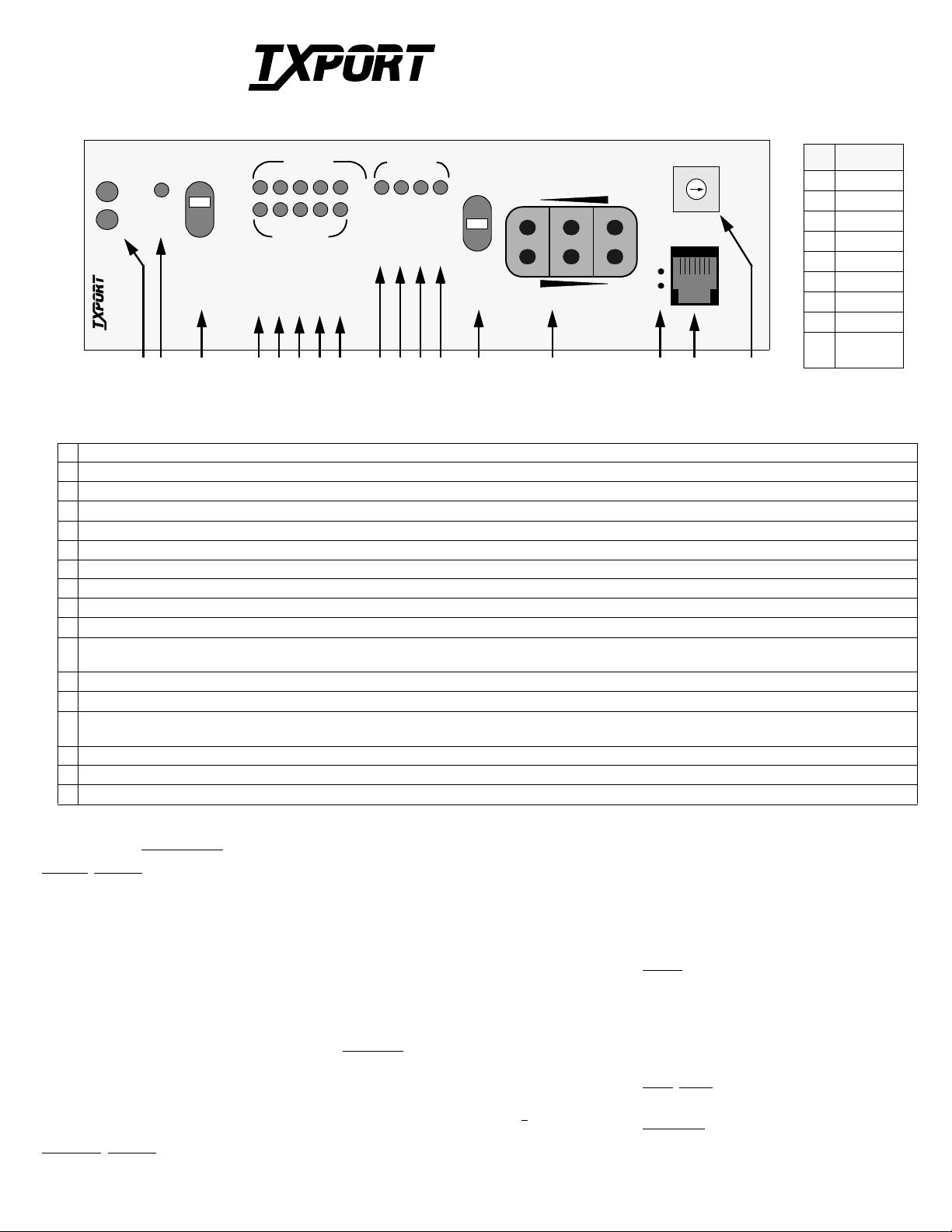
Pattern Select
Pos Patt ern
0QRW
12
22
32
42
52
7
9
15
20
23
61 in 8
73 in 24
9 PROM
Download
®
TRANSPORT
LLB
TST
PLB
TST
ERR
TO
LOC
NET
MON
T
E
D
STATUSPMU/NTU
ACO
E
T
N
FAR
ACO SW
2048
3 4
2 5 6 7 8 9 10 11 12 13 14 1615
1
BV/CR/FE
LOS/LOF
AIS
REM ALM
LOC ALM
NET
FRM
MON
DTE
FRM
TO
DTE
7
8
6
9
5
0
4
1
2
3
PAT SEL
1
6
S
UPV
17
Front Panel Description
1 Status: The green LED ligh ts when the unit is powered and operation is normal. The re d LED lights if an alarm exc ee di ng thresholds is detected.
2 Alarm Cut Off: This yellow LED lights if the Alarm Cut Off switch is pla ce d in the left ‘ON’ position. It indicates that the alarm relay contacts are disabled.
3 ACO Switch: This switch controls the alarm relay circuitry. If the switch is placed in the left ‘ON’ position, this circuitry is deactivated.
4 BV/CR/FE: This LED lights 1 second for each second that has an occurrence of bipolar violations, cyclic redundancy check errors, or frame bit errors.
5 LOS/LOF: Thi s LED bli nks wi th l oss of signal (LOS) from the network or DTE. It light s const an tly when a loss of frame (LOF) condition is detected.
6 AIS: This LED light s if an unframed all ones condition (alarm indicatio n signal) is detected from the network or equipment.
7 Remote Alarm: This LED lights constantl y when a remote (yellow) alarm signal is received from the far end.
8 Local Alarm: T h i s LE D lights when a local alarm exceeding al arm thresholds exist s . It remains lit until the Alarm Reset Timer pe riod ends.
9 LLB: This LE D lights continuously whe n the network interface is in a line loopback. It flashes when the DTE interface is in a line loopback.
10 PLB: This LED lights continuously when the ne twork interface is in a payload loopback.
11 TST: This LED lights continuously during a far or local test. It flashes when loop codes are transmitted at the start of a ‘far’ test and when unloop codes are
transmitted at the end of a ‘far’ te st.
12 ERR: This LED lights for 1 second when BE RT pattern errors are received during a ‘Far’ test.
13 Test Switch: This switch is used for local testing. If transmi tt ing IB L C, the test LED blinks. If transmit ti ng a test pattern, it lights con ti nuously.
14 Test Jacks: These jacks prov ide access to the T1 li ne on the DTE side – th e top 2 jacks break c onnection to the DTE and make connection to the unit in the direc ti on
of the network, the midd l e 2 ports monitor the signal s passing through the unit, and the bottom 2 ports br eak connection to the unit and make connection to the DTE.
15 Activity LEDs: These 2 small, recessed LEDs are provided to indicate supervisory and NMS port activity.
16 SUPV: This 6-pin supervisory jack provides di re ct ter minal access for PMU control and to gathe r status/facility performan ce dat a.
17 Pattern Select: This rotary swit ch det er mi ne s the BERT pattern sent by the unit when the test switch (Item 14) is in the ‘FAR’ position. Refer to th e ta ble above.
Specifications
Network Interface
Line Rate: 2.048 Mb/s, ± 50 ppm, P CM -30
Multi -frame Type: CAS and/or CRC4, or none
Line Code: AMI or HDB3
Connection: 120 ¾ balanced or 75 ¾ unbal.
Backplane: DB15, Twin-axial, and BNC
Output Signal: 75¾ mark 2.37 V, space 0±0.237 V
(per G.703) 120 ¾ Mark 3 V, Space 0 ± 0.3 V
Line Build Out: 0, - 7. 5, -1 5 dB switch settings
Input Signal: 75 ¾ mark 2.37V, space 0 ±0.237V
(per G.703) 120 ¾ Mark 3 V, Space 0 ± 0.3 V
attenuated by 0 to -27 dB (ALBO)
Jitter Attenuation: per CCITT G.823
AIS: Unframed or framed all ones, or
(user selectable) line loopback
Overvoltage: 1000 V minimum protection
Equipment
Line Rate: 2.048 Mb/s, ± 50 ppm, P CM -30
Multi-frame Type: CAS and/or CRC4, or none
Interface
Line Code: AMI or HDB3
Output Signal: 75¾ mark 2.3 7 V, space 0±0. 237 V
(per G.703) 120 ¾ Mark 3 V, Space 0 ± 0.3 V
Pulse Width: 244 ns, nominal
DTE Input Signal: 75¾ mark 2.37V, space 0 ±0.237V
(per G.703) 120 ¾ Mark 3 V, Space 0 ± 0.3 V
attenuated by 0- 6 dB @ 1024 kHz
Connection: 120 ¾ balanced or 75 ¾ unbalanced
Backplane: DB15, Twin-axial, and BNC
AIS: Unframed or framed all ones, LLB
Overvoltage: 1000 V minimum protection
Diagnostics
Line Loopback: Signal regeneration only
Payload Loopback: Signal regenerated with new frame
synchronization and CRC4
BERT: 63, 511, 2047 , 2
23
, QRW, and ALT
2
15
(default), 220,
BERT Activation: Front panel switch, user selection of
patterns via command. Pattern sync
/ bit errors reported via command.
Loopback Control: Inband loop up, 00001 for Ý 5 sec
Inband loop down, 001 for Ý 5 sec
User enable/dis able, Manual loop
back switch, FDL loopback comnd.
PTT and EM8000 Full ESF performance monitori ng
through 6-pin RJ11 termi nal port,
and via FDL in sele cted national bi t
Alarms
Contacts: Normally Open or Normally Closed
(screw terminal connection)
Activation: Programmable
Reporting: Through TxPORT EM8000
Cut Off: Manual, 2-position switch
Local
Power
-48 VDC (± 10%), 75 mA max (screw terminal)
Mechanical
Mounting: Wall, horizontal or vertical rac k
Dimensions: 1.75" W, 6.0" H, 11.75" D
Weight: 1 pound
Page 2
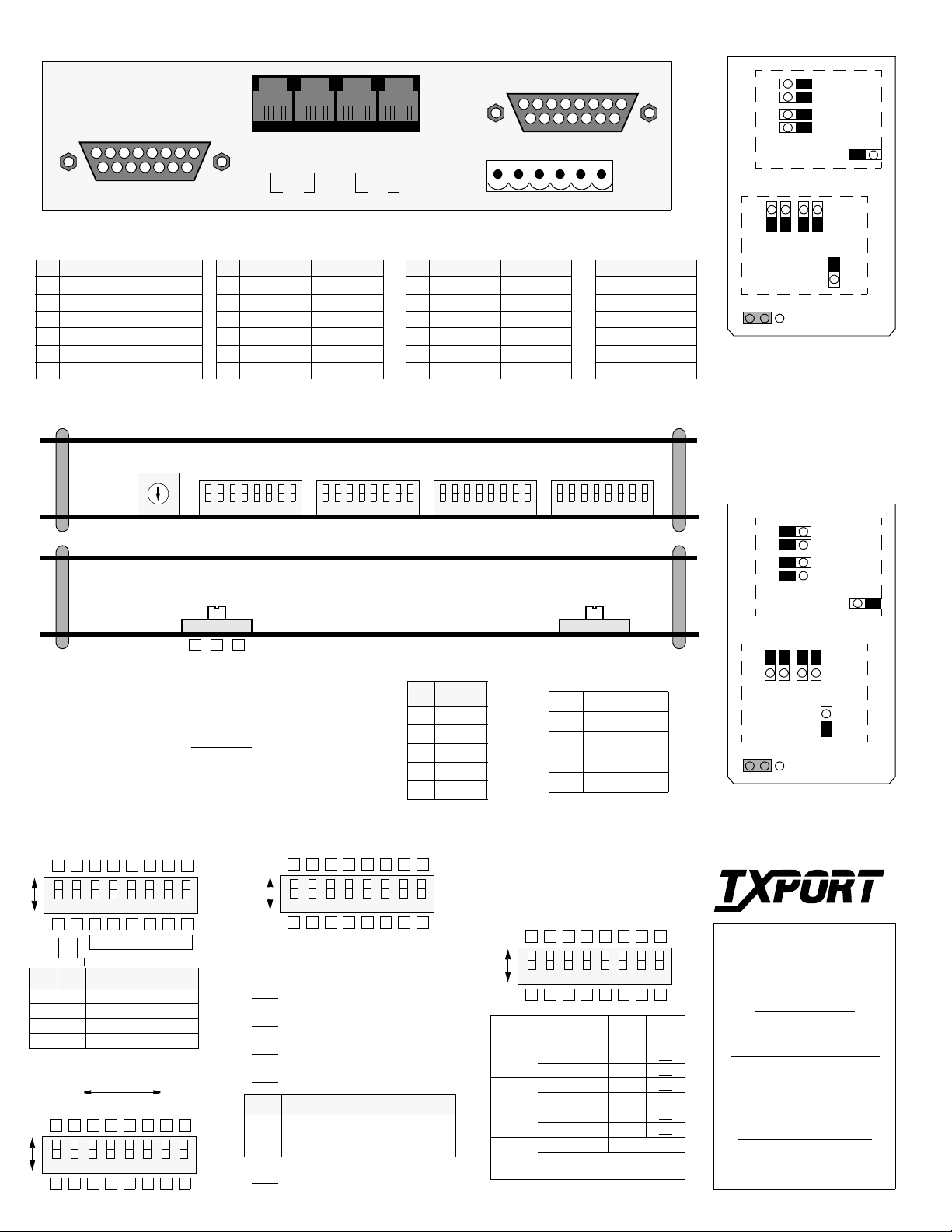
2048 PMU Rear Panel (with DB15)
J
4
8
P
E
T
Q
1
6
1
IN
15
9
USER
Equipment/Network Connection
Pin EQPT DB15 NET DB15
1 Data In Data Out
2 Frame Ground Frame Ground
3 Data Out Data In
4 Frame Ground Frame Ground
9 Data In Data Out
11 Data Out Data In
Switch SW2
5
6
4
3
8
2
179
0
Switch S1:
PTT should provide the proper setting. Check the box which corresponds
to your LBO setting. If unsure of the exact setting, then slide to 0 dB.
Sets the output signal level (LBO) of transmitted data. The
Pin EQP T RJ48 NET RJ48
1 Data Out Data In
2 Data Out Data In
3/6 Not Used Not Used
4 Data In Data Out
5 Data In Data Out
7/8 Chassis Gnd Chassis Gnd
Switch S4
18765432
S1
6
1
IN
OUT
OUT
PTT
Pin NMS In /Out NMS Out
1 Not Used Not Used
2 Signal Gnd Signal Gnd
3 Data Out Data Out
4 Data In Not Used
5 Signal Gnd Signal Gnd
6 Not Used Not Used
Circuit Board View
Switch S5
18765432
P
1
9
1
User/PTT Connection
Switch S6
18765432
Switch S2:
Tx/Rx pair for either normal stand-alone
use or for chassis nest mount use.
This switch swaps the DTE
NORM RACK
2
E
T
N
8
15
Power/
6
Power/Alarm
Pin Function
1 48 VDC Return
2 Signal Ground
3 -48 VDC
4 Frame Ground
5 Alarm Contact
6 Alarm Common
Switch S7
18765432
S2
Alarm
75 ¾ Jumper Configuration
Front
J5
J6
J7
J8
Equipment
Network
J18
NO NC
J14
J15
J16
Rear
J4
J12J13
Alarm Relay: Pin 5 on the
P ower/Alarm terminal strip is
configured to operate either in
a normally open (NO) or a
normally closed (NC) mode as
determined by Jumper J18.
120 ¾ Jumper Configuration
Front
J5
J6
J7
J8
Equipment
J4
-15 -7.5 0
NOTE: F or futur e refer enc e, all DIP switches ar e
provided with upper and lower boxes to check
according to the particular user selec tion. F actory
default settings are shown underlined
.
NOTE: On all switches, the ‘Up’ or ‘1’ position is
OPEN and the ‘Dn’ or ‘0’ position is CLOSED.
Configuration Switch S4
7
Dn Up
Spares
Pos 1 Pos 2 Configuration Mode
Dn Dn Boot from switches
Dn Up Download from manager
Up Dn Boot from RAM
Up Up Boot from ROM
Address Switch S7
MSB LSB
64
32
16
8
4
2
1
7
Dn Up
8654321
128
8654321
Configuration Switch S5
Dn Up
Sets the BERT data polarity to a ‘1’ or ‘0’.
S5-1:
- 1 Up - 0 (inverted)
Down
IBLC - Enables the inband 5-bit loop up
S5-2:
code and 3-bit loop down code detection.
Down
- Enabled Up - Disabled
Matches the PMU to the line framing used.
S5-3:
- CAS Up - CCS
Down
Sets the network line code for the E1 signal.
S5-4:
- HDB3 Up - AMI
Down
Enables the CRC4 framing format.
S5-5:
- Enabled Up - Disabled
Down
Pos 6 Pos 7 AIS/Keep Alive Selection
Dn Dn AIS is unframed all ones
Dn Up AIS is framed all ones
Up Dn Line Loopback (LLB)
Enables CRC4 Insert on the network side.
S5-8:
- Disabled Up - Enabled
Down
Switch SW2
Pos Nat’l Bit
11
22
33
44
55
8654321
7
Supervisory Port
(front pan el)
1/6 Not Used
2 Signal Ground
3 Data Out
4 Data In
5 Signal Ground
Configuration Switch S6
Supervisory
Supervisory
User NMS
User NMS
PTT NMS
Dn Up
1.2
2.4
kb/s
kb/s
kb/s
SUPV - 1
User - 3
PTT - 5
Nat’l - 7
Bit - 8
Dn Dn Up Up
- 2
Dn Up Dn Up
Dn Dn Up Up
- 4
Dn Up Dn Up
Dn Dn Up Up
- 6
Dn Up Dn Up
Dn (0) = Pass Up (1) = Select
Select Dn (0) or Up (1) for nat’l
bit if S6-7 is set to ‘Select’
9.6
J13
J14
J15
J16
J12
Network
J18
NO NC
PTT NMS
National bit
National bit
TRANSPORT
Rear
®
TxPORT
127 Jetplex Circle
8654321
7
19.2
kb/s
Madison, Alabama 35758
Customer Service
800-926-0085, ext. 227
Product Technical Support
(8 a.m. to 5 p.m. Central)
800-285-2755 or
205-772-3770
Emergency After Hours
Support: 800-285-2755
INET: support@txport.com
 Loading...