

Page 1

Introduction
2048
PMU/NTU
®
TRANSPORT
Reference Manual
34-00179
2nd Edition
Page 2

Table of Contents
Operation
Introduction .................................................................3-1
Front Panel Descriptions .............................................3-1
General
Introduction ................................................................. 1 -1
Design Highlights ....................................................... 1 - 2
Specifications .............................................................. 1-2
FCC /European Requirements .................................... 1 -3
Warranty ...................................................................... 1 - 3
Ordering Numbers ...................................................... 1 - 4
TxPORT Customer Service ....................................... 1 - 4
Installation
Introduction ................................................................. 2 -1
Safety Summary ......................................................... 2-1
Unpacking And Inspection ........................................ 2 - 1
Supplied Materials ...................................................... 2-1
Mounting ..................................................................... 2 -1
Stand - alone Unit ................................................. 2 - 1
Chassis Assembly ............................................... 2-2
Unit Configuration ..................................................... 2- 2
Switch SW1 (BERT Pattern) ............................... 2-2
Switch SW2 (National Bit) ................................. 2-2
Switch S1 (Network LBO) .................................. 2-2
Switch S2 (Chassis Operation) ........................... 2-3
Switch S4 (Configuration) ................................... 2-3
Switch S5 (Configuration) ................................... 2-3
Switch S6 (Bit Rate Selection) ............................. 2-4
Switch S7 (Address) ............................................ 2-4
Equipment Connection ................................................ 2-5
Network Connection ................................................... 2-5
Network Management ................................................ 2 -5
Supervisory Port ................................................... 2-5
PTT Port .............................................................. 2 - 6
User Port ............................................................. 2-7
Chassis Network Management ............................. 2-7
Alarm Connection ....................................................... 2-8
Stand - alone Unit ................................................. 2 - 8
Chassis Assembly ............................................... 2-8
Power Connection ...................................................... 2 -8
Stand - alone Unit ................................................. 2 - 8
Chassis Assembly ............................................... 2-8
General Status Indicators ................................... 3 - 1
Alarm Controls & Indicators ..............................3 -1
Test Controls & Indicators .................................3-2
Front Panel Testing .....................................................3-2
Test Switch ......................................................... 3-2
Test Access Jacks ..............................................3-2
Supervisory Port ................................................. 3-2
BERT Pattern Select ............................................3-2
Terminal Operation
Introduction ................................................................. 4 -1
System Description ..................................................... 4-1
Modem Compatibility .......................................... 4-1
Screen Components ............................................. 4-1
Interface Start Up ................................................. 4-2
Daisy-Chain Menu Operation ............................. 4-2
Cursor Controls .................................................... 4-2
Field Types .......................................................... 4-3
Main Menu Screen ...................................................... 4-3
Alarms Screen ............................................................. 4-4
Performance Screens ................................................... 4-5
Maintenance Screen .................................................... 4-7
Test Loops ........................................................... 4-8
BERT ................................................................... 4- 8
Line Fault and Loop Status .................................. 4-8
Configuration Screens ................................................. 4-9
Line Configuration .............................................. 4-9
Alarm Configuration ............................... ...... ...... . 4-10
Utilities Screen ............................................................ 4-10
General Functions ................................................ 4-11
COA Parameters .................................................. 4 - 11
Index
Configuration Guide
Page 3

Copyright / Liability
Copyright
© 1995 TxPOR T, All rights re served. No part of this pub licatio n may be repro duced, transmitted, transcribed, stored in a retrieval system, or translated into any language in any form
by any means without the written permission of TxPORT.
Reorder # 34-00179
2nd Edition, July 1995
TxPORT shall not be liable for errors contained herein or for incidental or consequential
damages in connection with the furnishing, performance, or use of this material. TxPORT
reserves the right to revise this publication from time to time and make changes in content
without obligation to notify any person of such revision changes.
Contents of this pu blication m ay be prelimin ary and/or may be changed at an y time with out
notice and shall not be regarded as a warranty.
Documentation Disclaimer
TxPOR T makes no representation or war ranties of any kind whatsoe ver with respect to the
contents hereof and specifically disclaims any implied warranties of merchantability or fitness for any particular purpose.
Page 4
General
1.0 Introduction
The TxPORT International 2048 PMU /NTU (Performance
Monitoring Unit /Network Terminating Unit) is an advanced
network device capable of operating in framed or multi-
framed (G.704) modes, using AMI or HDB3 line coding.
The 2048 is designed for CEPT E1 (2.048 Mb/s) connection
to the PTT (the national Postal, Telephone, and Telegraph
authority) by the user. The unit provides end -to-end inband
protocol via a selectable national bit. This allows one PMU
to interrogate and control the remote far end PMU.
The 2048 is equipped with a dual set of performance data
registers that hold line statistics for both the PTT and the
user. Each register set provides detailed status and performance history for the network and equipment interfaces.
front panel test switch activates local/remote loops and controls the internal BERT generator and comparator.
The optional EM8000 Element Manager is available for
applications requiring multiple PMUs. The EM8000 provides access, control, testing, alarm reporting, and database
management functions.
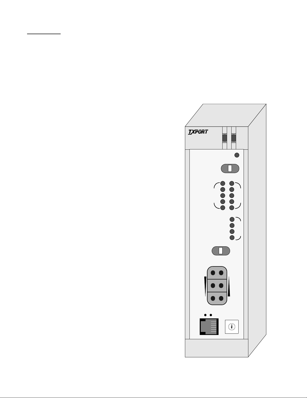
TxPORT 2048 PMU/NTU
TRANSPORT
PMU/NTU
®
2048
ACO
The PTT performance data registers may be accessed, read,
and cleared by the PTT. User registers can only be accessed
by the user. Both registers contain identical core performance information, but the user registers also contain additional fields relating to unit configuration and status.
Performance data (per TR54016 and G.821/ X) is collected
in 15- minute increments for the preceding 24- hour period
and in 24 - hour increments for the preceding 30 -day period.
The unit enables downloading of remote site performance
data from the far end PMU, in all modes of operation, using
the facility data link (user selectable national bits).
The PMU provides access to the data registers through one
front and two rear management ports. These ports provide
test, diagnostics, and control over the CEPT E1 network.
Program upgrades may be downloaded into electrically erasable memory (EPROM) in the field via the supervisory port
on the front panel.
Access can also be obtained through a data link using an
assigned national bit. The national bit data link uses the
54016 U.S. FDL TABS protocol and message set. Additional request/response FDL messages have also been added
to enhance the PMU’s operation. The TxPORT EM8000
network manage r uses these messages to provid e complete
end-to-end control and performance monitoring.
The 2048 also provides features to aid in quick fault isolation. Front panel indicators display alarm and test conditions. Test jacks allow bridged monitoring of the passed
signal and signal insertion toward the PTT or the user. A
ACO SW
BV/CR /FE
LOS/LOF
AIS
REM ALM
LOC ALM
FAR
FRM
NET
MON
TO
DTE
S
U
P
V
N
E
T
LLB
PLB
TST
ERR
4
3
2
1
MON
FRM
SW1
5
0
LOC
TO
NET
DTE
6
9
7
8
D
T
E
T
S
T
General 1-12048 PMU/NTU
Page 5

1.1 Design Highlights
• End-to-end user control and access to
extensive unit performance data
unit configuration
unit status (normal, looped, alarm)
DTE Input Signal: 75 ¾ mark 2.37 V, space 0 ± 0.237 V
(per G.703) 120 ¾ mark 3 V, space 0 ± 0.3 V
attenuated by 0 to -6 dB at
1024 kHz (0 dB = 2.4 V)
Connection: 120 ¾ balanced or 75 ¾ unbalanced
• AMI or HDB3 coding
• User and PTT access via FDL link
• Dual performance registers - User and PTT/carrier
• Jitter control of network signal (per G.823)
• Complete diagnostic capabilities, including multiple
loopbacks and buil t-in BERT
• Front panel test jacks, alarm indicators, and test switch
1.2 Specifications
Network Interface
Line Rate: 2.048 Mb/s, ± 50 ppm, PCM-30
Multi-frame Type: CAS and/or CRC4, or none
Line Code: AMI or HDB3
Connection: 120 ¾ balanced or 75 ¾ unbalanced
Backplane: DB15, Twin-axial, and BNC options
Output Signal: 75 ¾ mark 2.37 V, space 0 ± 0.237 V
(per G.703) 120 ¾ mark 3 V, space 0 ± 0.3 V
Line Build Out: 0, -7.5, -1 5 dB switch settings
Input Signal: 75 ¾ mark 2.37 V, space 0 ± 0.237 V
(per G.703) 120 ¾ mark 3 V, space 0 ± 0.3 V
attenuated by 0 to -27 dB (ALBO)
Backplane: DB15, Twin- axial, and BNC options
AIS: Unframed or framed all ones, or
line loopback
Overvoltage: 1000 V minimum protection
Diagnostics
Line Loopback: Signal regeneration only
Payload Loopback: Signal regenerated with new frame
synchronization and CRC4
BERT: 63, 511, 2047, 2
BERT Activation: Front panel switch for test. User
Loopback Control: Inband loop up, 00001 for Ý 5 sec
PTT and EM8000 Full ESF performance monitoring
23
2
, QRW, and ALT
selection of BERT patterns via
command. Pattern sync and bit
errors reported via command.
Inband loop down, 001 for Ý 5 sec
User enable/disable
Manual loopback switch
FDL loopback command
through a terminal port (6-pin RJ11),
and via FDL in selected national bit
15
(default), 220,
Jitter Attenuation: per CCITT G.823
AIS: Unframed or framed all ones, or
(user selectable) line loopback
Overvoltage: 1000 V minimum protection
Equipment
Line Rate: 2.048 Mb/s, ± 50 ppm, PCM-30
Multi-frame Type: CAS and/or CRC4, or none
Line Code: AMI or HDB3
Output Signal: 75 ¾ mark 2.37 V, space 0 ± 0.237 V
(per G.703) 120 ¾ mark 3 V, space 0 ± 0.3 V
Pulse Width: 244 ns, nominal
1-2 General 2048 PMU/NTU
Interface
Access
Jack
Toward Network: Bantam jacks (In, Out, and Monitor)
Toward DTE: Bantam jacks (In, Out, and Monitor)
Access
User Net Manager: Asynchronous, RS232
Telco Net Manager: Asynchronous, RS232
Local Access: Asynchronous, RS232
Bit Rates: 1200, 2400, 9600 or 19200 b/s
(all ports) (switch selectable)
Formats: 8 data bits, 1 stop bit, no parity
Ports
Page 6

Protocol: TxPORT COMVIEW (pro prietary)
!
ASCII VT100
Connection: All ports, 4-pin modular
G.732 primary PCM multiplex @ 2.048
G.821 error performance criteria
G.823 co ntrol of jitter and wander
Alarms
Contacts: Normally Open or Normally Closed
(screw terminal connection)
Activation: Programmable
Reporting: Through TxPORT EM8000 manager
Cut Off: Manual, 2-position switch
Mechanical
Mounting: Wall, vertical, or horizontal rack
Width: 1.75"
Height: 6"
Depth: 11.75"
Weight: 1 pound
Power
Local Power: -48 VDC (± 10%)
75 mA maximum
(screw terminal connection)
G.832 framing requirements
TR54016 performance data
1.3 FCC/European Requirements
WARNING: Changes or modifications to this
unit not expressly approved by the party responsible for
compliance could void the user’s authority to operate the
equipment.
FCC and European homologation pending.
This equipment generates, uses, and can radiate radio fre-
quency energy and, if not installed and used in accordance
with the instruction manual, may cause harmful interference
to radio communications. Operation of this equipment in a
residential area is likely to cause harmful interference in
which case the user will be required to correct the interference at his own expense.
Shielded cables must be used with th is unit to ensure compliance.
Battery
The unit’s configuration and operating parameters are stored
in nonvolatile RAM memory. In case of a power outage and
if the DIP switches are set to boot from RAM, then the
unit’s memory is checked upon power- up conditions. If the
RAM has been compromised, the unit’s configuration will
revert to the options set with the remaining DIP switches.
Environmental
Operating Temp: 0° to 50° C (32° to 122°F)
Storage Temp: -20° to 85° C (-4° to 185°F)
Humidity: 95% max (non-condensing)
Compatibility
G.703 signal waveform
G.704 synchronous frame structures
Backed RAM
1.4 Warranty
TxPORT warrants each unit against defects in material and
workmanship for a period of five years from the date the
unit was shipped to the customer. If the unit malfunctions at
any time during the warranty period, TxPORT will repair, or
at TxPORT’s option, replace the unit free of charge.
The remedies listed herein are the user’s sole and exclusive
remedies. TxPORT shall not be liable for any indirect,
direct, incidental or consequential damages. The owner must
return the unit to the factory, shipping prepaid and packaged
to the best commercial standard for electronic equipment.
TxPORT will pay shipping charges for delivery on return.
The customer is responsible for mode and cost of shipment
to TxPORT. This warranty does not apply if the unit has
been damaged by accident, misuse or as a result of service
or modification by othe r than TxPORT personnel.
When returning the unit for warranty work, a Return Material Authorization (RMA) number must be obtained from
customer service at the address/phone number shown in
Section 1.6. When calling TxPORT to obtain a Return Mate-
General 1-32048 PMU/NTU
Page 7

rial Authorization number or to arrange service, please have
the following information available:
• Model number(s) and serial number(s) for the unit(s).
• Reason for return and symptoms of problem.
• Warranty status (if known).
• Purchase order number to cover charges for out-ofwarranty items.
• Name and phone number of person we can contact if
we have questions about the unit(s).
• Mode of shipment required (second day air is the normal mode of shipment for all returned material unless
otherwise specified).
As soon as TxPORT has the above information, the RMA
that must accompany the item(s) returned can be issued.
1.5 Ordering Numbers
The unit is shipped from the factory with the 2048 PMU/
NTU reference manual. Refer to Table 1 -1 for optional
equipment part numbers.
The part numbers for the stand- alone unit and the modular
chassis unit are shown in the following table:
Part Number Description
Table 1-1 Optional Equipment
Part Number Description
Cables
9 - 1001 - 027- 1
9 - 1001 - 027- 2
9-1001-028-1
9-1001-028-2
9-1001-029-2 DB9 female to 6-pin RJ11 (terminal to SUPV)
9-1001-048-1
9-1001-048-2
33-00085
33-00086
F-1051-000--112 Twelve-slot 1051 chassis with RJ48C and DB25
9-2000-001--1
9-2000-001--2
9-2000-002--1
9-2000-002--2
9-2000-036--1 Stand-alone to rack mount conversion module
F-1040-000--110
9-1000-48V-1
F-1041-000--110
9-1000-48V-2
30-00087 Stand-alone wall mount power supply
9-8000-001-1
9-8000-001-2
DB25 male to 6-pin RJ11 (modem to SUPV)
DB25 female to 6-pin RJ11 (modem to SUPV)
DB25 male to 6-pin RJ11 (terminal to SUPV)
DB25 female to 6-pin RJ11 (terminal to SU PV )
DB25 male to two 6-pin RJ11 (terminal to NMS)
DB25 female to two 6-pin (terminal to NMS)
Bantam to bantam test cord - red
Bantam to bantam test cord - black
Mounting
backplane connectors
19" single unit rack mount bracket
19" dual rack mount bracket
23" single unit rack mount bracket
23" dual rack mount bracket
with DB25 to 6-pin adapter
Power
1040 power shelf (type 400 mechanics)
w/o power supplies
One -48V/2A power supply (1040 holds 2)
Redundant 1041 power shelf (type 400
mechanics) w/o power supplies
One -48V/2A power supply (1041 holds 2)
(- 4 8VDC/200mA)
Misc.
EM8000 with manua l on 3-1/2 inch disk (DOS
and UNIX version, respectively)
F-2048-100-11
C
2048 PMU/NTU stand-alone unit
C
=
Backplane option
1
with BNC connector
2
with Tri-axial connector
3
with Twin-axial connector
4
with DB15 connector
5
with BNC and DB15
1.6 TxPORT Customer Service
TxPORT
127 Jetplex Circle
Madison, Alabama 35758
T e l eph one Nu mber: 800-926-0085 or
F-2048-101-111
2048 PMU / NTU module (chassis)
205-772-3770
Sales /Administration FAX: 205-772-3388
Manufacturing FAX: 205 -772 - 8280
For example, the default part number for the stand-alone
Customer Service Returns: 800-926-0085, ext. 227
unit is ‘F – 2048– 100 – – 111’. This is a unit equipped
with BNC connectors on the backplane.
Product Technical Support (Normal Hours)
8 a.m. to 5 p.m. Central Time, Monday – Friday)
T e l eph one Nu mber: 800-285-2755 or
205-772-3770
Emergency (Nights / Weekends / Holidays)
The following accessories may also be needed for the installation and operation of the TxPORT 2048 PMU/NTU.
T e l eph one Nu mber: 800-285-2755
Internet Address: support@txport.com
1-4 General 2048 PMU/NTU
Page 8

Installation
2.0 Introduction
This section contains information and instructions required
to prepare the 2048 PMU for use. Included are initial
inspection procedures, mounting instructions, configuration
guidelines, connection instructions, and powering information.
NOTE: Throughout this manual, all factory default
settings will be underlined
.
2.3 Supplied Materials
The TxPORT 2048 PMU /NTU is shipped from the factory
with the following equipment:
• 2048 PMU with 19" mounting brackets attached
• 2048 PMU Reference Manual
The user may also require the following additional materials
for the installation and operation of the 2048 PMU.
• -48 VDC power source
• A wall transformer to provide 110 VAC to -48 VDC
local power
• Network and DTE interface cables
2.1 Safety Summary
This manual contains information and warnings which must
be followed by the user to ensure safe operation and to
retain the equipment in a safe condition.
!
The WARNING sign denotes a hazard to the
operator. It calls attention to a procedure or practice
which, if not correctly performed or adhered to, could
result in injury or loss of life. Do not proceed beyond a
WARNING sign until the indicated conditions are fully
understood and met.
NOTE: Follow the proper ESD (electrostatic device)
procedures while handling the circuit boards.
2.2 Unpacking and Inspection
This unit is carefully packaged to prevent damage in shipment. Upon r eceipt, ins pect th e shipping contai ner for damage. If the shipping container or cushioning material is
damaged, notify the carrier immediately and make a notation on the delivery receipt that the container was damaged
(if possible, obtain the signature and name of the person
making delivery). Retain the packaging material until the
contents of the shipment have been checked for completeness and the instrument has been checked both mechanically
and electrically.
If the contents of the shipment are incomplete or, if there is
mechanical damage or defect, notify TxPORT. If the shipping container is also damaged, or the cushioning material
shows signs of stress, notify the carrier of the damage as
well as TxPORT. Keep the shipping materials for carrier’s
inspection. TxPORT will arrange for repair or replacement
without waiting for claim settlement.
• 20-gauge stranded wire (or similar) for DC power
and alarm connection
For specific applications, the user may require additional
cables and adapters. The interface requirements of any
application may be met by using the appropriate cable. Standard cables an d ord ering n umber s are lis ted in Table 1 -1 on
page 1-4. Contact TxPORT for any needed assistance in
cable selection.
2.4 Mounting
The 2048 PMU is a modular unit that plugs in to eith er a single unit housing or into a chassis that holds up to 12 units.
Single units are designed for stand - alone desktop use, wall
mounting, or chassis mounting (in either a vertical or horizontal orientation). The unit uses an interchangeable front
panel to accommodate the chassis card cage.
The unit utilizes an interchangeable backplane to accommodate the nest mount card cage and, when used in the single
unit housing, to provide various connector types for differing application requirements. Backplane options for the
2048 include DB15, Twin-axial, and BNC connectors.
2.4.1 Stand-alone Unit
To access the circuit boards and configuration switches, perform the following steps: Open the front panel access door
and remove it by gently bending the plastic from th e middle
using both hands. Then pull the two side strips of plastic
from the middle outwards until the four stops are clear of
the front panel. Pull the cover off the front panel. Then
remove the 2 screws and pull the front panel and circuit
boards out of the housing. Observe proper electrostatic
device handling procedures while holding the circuit boards.
Installation 2-12048 PMU/NTU
Page 9
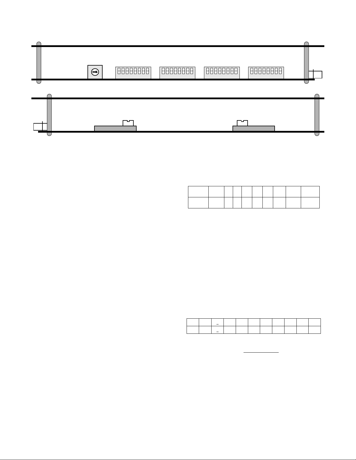
Figure 2-1 Circuit Board Views
0
1
9
2
8
3
7
6
4
5
2048
rear
Switch S1
-15 -7.5 0
The stand -alone unit may be used in a chassis installation
with the following modifications: Remove the housing as
described above and then remove the four screws holding
the front panel to the circuit boards. Replace the stand -alone
front panel with a module type front panel. The unit will
now slide into one of the 12 slots in the chassis.
2.4.2 Chassis Assembly
Up to 12 units may be inserted in to a chass is and the ch assis
may be installed in a 19" or 23" rack using four screws.
Connections are made from the rear of the chassis. Refer to
the figures on page 2-10 for these illustrations.
Switch S6Switch S5Switch S4Switch SW2
NORM RACK
Switch S7
1234567
Switch S2
8123456781234567812345678
2048
rear
tern as determined by rotary switch SW1 (refer to the following table). This switch is located on the front panel
(shown on page 3-1).
Pos
Pattern
PROM Downloading Procedures:
0 12345 6 7 9
QRW 2
729215220223
1:8 3:24 PROM
Rotary switch SW1,
position 9 is used to download new PMU operating firmware into the flash memory. This operation requires a PC
and a diskette which contains TxPORT’s downloading program (
download.exe
) and the hex file to be downloaded.
Downloading procedures are described in the 2048 Download Procedures document sent with the software.
2.5 Unit Configuration
2.5.2 Switch SW2 (National Bit)
The 2048 PMU model is designed as a two card set. The
two cards roughly divide into analog and digital functions.
The unit provides an interface to the network in compliance
with established standards. It has been designed to operate
either manually or through the use of a console/terminal.
Therefore, the unit has both hardware and software configuration settings.
This following paragraphs explain the various hardware
configurations that may be adjusted for unique applications.
Software controlled settings are discussed i n the Operations
section of this manual.
2.5.1 Switch SW1 (BERT Pattern)
When the PMU is instructed to send a test pattern by the test
switch (FAR/LOC) on the front panel, it will send 5 seconds
of inband loop code (10000) and then transm it the test pat-
2-2 Installation 2048 PMU/NTU
Rotary switch SW2 is used to select th e National Bit. The
following table shows the switch positions. The factory
default is position 1.
Pos
NB
01
N/A 1
2345678 9
23454 4 4 4
Switch S6 has two positions affecting the optio ns fo r Switch
SW2. For position S6- 7, Down = ‘Pass’
and Up = ‘Select’.
For position S6 -8, select eith er ‘Down’ (0) or ‘Up’ (1) for
National Bit data (applies only if position S6-7 is set for
‘Select’). Switch S6 is cov ered in Sectio n 2.5.7 on pag e 2-4.
2.5.3 Switch S1 (Network LBO)
The output signal level of the transmit data (TXD) from the
2048 PMU to the network must be set by the LBO switch
Page 10
located on the bottom of the PC board (refer to the bottom
7654321 8
Dn Up
Ones Polarity
1
IBLC
Enable
Signal
CAS
Code
HDB3
CRC4
Enable
AIS / KA
AIS / KA
Insert CRC
Disable
Ones Polarity0IBLC
Disable
Signal
CCS
Code
AMI
CRC4
Disable
AIS / KA
AIS / KA
Insert CRC
Enable
Switch
S5
circuit board view in Figure 2-1).
The output level is factory set at 0 dB
. It may be attenuated
by -7.5 dB or by - 15 dB if operating conditions require that
it be changed. The PTT should provide the proper setting to
the user.
If unsure of the exact setting, then slide to 0 dB.
AIS: Unframed all ones
Keep Alive: AIS
BERT Ones polarity: 1 (normal)
National Bit Position: 4
National Bits: Pass
BERT Polarity: Normal
2.5.4 Switch S2 (Chassis Operation)
Switch S2 is used to swap the DTE transmit and receive pair
(Tx/Rx) for either normal stand-alone use or for rack mount
2.5.6 Switch S5 (Configuration)
DIP Switch S5 is used to set the following configuration
parameters on the 2048 unit.
use. It is located on the bottom of the PC board (refer to the
bottom circuit board view in Figure 2-1).
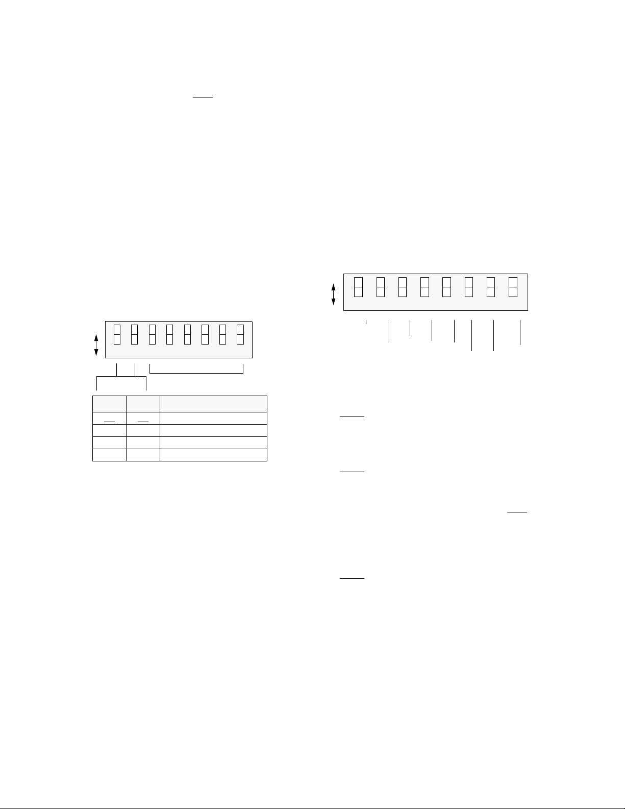
2.5.5 Switch S4 (Configuration)
During initial power up, four modes of configuring the 2048
are available using the first two positions of DIP Switch S4.
Switch
7654321 8
Dn Up
Spares
Pos 1 Pos 2 Power Up (Boot) Mode
Dn
Dn Up Boot from Manager
Up Dn Boot from RAM
Up Up Boot from ROM
Dn Boot from Switches
S4
One’s Polarity: Position S5-1 sets the bit error rate test
(BERT) data ones polarity to either a 1 or 0.
: ‘1’ Up: ‘0’ (Inverted)
Down
IBLC: P osition S5-2 enables inband 5-b it (10000) loop up
code and 3-bit (100) loop down code detection.
:Enabled Up:Disabled
Down
1) Boot from switch settings: Upon reset, the unit reads
its configuration from the hardware switch settings
described in this chapter.
Line Framing: Position S5- 3 is used to m atch th e PM U to
the framing format used. The options are CAS
(Channel
Associated Signalling) or CCS (Common Channel Signal-
2) Boot from manager: Upon reset, the unit requests configuration information from the EM8000 element manager.
If the manager is not on-line, the unit will boot from RAM.
3) Boot from RAM: Up on reset, the unit reads its configuration from the internal, battery-backed RAM.
4) Boot from ROM: Upon reset, the unit reads its configuration from the internal ROM. The ROM factory default settings are as follows:
ling). CAS is also referred to as PCM30, (or CAS Multiframe). CAS framing also includes an additional FAS sync
word in time slot 16, frame 0.
Down
: CAS Up: CCS
CCS is also referred to as PCM31 (or no Multiframe). It
contains alternating aligned frames and non-aligned frames.
If the PMU is configured for CCS, it will pass both CCS and
CAS framing data. In this case, the additional FAS sync
word in the CAS mode is passed as data and the PMU does
Signalling: CAS
Network CRC4: Enabled
DTE CRC4: Enabled
Line Code: HDB3
Inband Loop Code: Enabled
not try to sync on the additional sync word.
If CAS framing is used, then a more rigid sync and error
detection is used by the PMU. If CAS is selected, the PMU
expects CAS framing. If CCS framing is used, the PMU
declares an out of sync condition and transmits the Keep
Installation 2-32048 PMU/NTU
Page 11

Alive (KA) option. The PMU expects the framing format to
be the same on the equipment and network sides.
Network Line Code: Position S5 - 4 sets the network line
code for the E1 signal.
: HDB3 Up: AMI
Down
2.5.7 Switch S6 (Bit Rate Selection)
DIP Switch S6 is used to select the bit rates for the USER,
PTT, and the Supervisory ports. The national bit ‘Pass’ or
‘Select’ option is also included on this switch.
CRC4: Position S5 -5 enables
or disables the CRC4 fram-
ing mode. If enabled, the PMU will transmit the CEPT
CRC4 multiframe format and also expects to receive the
same format. The CRC4 checksum is the bases for obtaining
the performance monitoring data, so it important that this
position is enabled.
The PMU also expects to receive a CRC4 formatted input. If
the PMU is configured for CRC4 and a non -CRC4 format
signal is received, the PMU will indicate alarm conditions.
If the PMU is not configured for CRC4 and a CRC4 signal
is received, the PMU will ignore the CRC4 code. However,
the PMU will reframe the signal and the CRC4 code will not
be passed through the PMU.
The PMU always regenerates the CRC4 code, from the
equipment to the network. If both network and equipment
are configured the same, the PMU passes data from the network to the equipment with regeneration only. In this mode,
the BPV, FBE, and CRC errors are passed through the PMU.
Insert CRC: Positio n S5-8 enables or disables
the PMU to
insert CRC4 data on the network side of the PMU. If
enabled, the PMU will transmit and receive the CRC4 format on the network side only. Through the EM8000 network
manager, the PMU may be configured to enable/disable
CRC4 on either the network or equipment side.
Supervisory
Supervisory
USER NMS
USER NMS
PTT NMS
PTT NMS
Nat’l Bit
Nat’l Bit
Switch
Dn Up
SUPV
USER
NMS
PTT
NMS
Pos 1.2 kb/s 2.4 kb/s 9.6 kb/s 19.2 kb/s
1DnDnUp Up
2DnUpDn Up
3DnDnUp Up
4DnUpDn Up
5DnDnUp Up
6DnUpDn Up
7654321 8
Position S6-7: National bit, Dn = Pass
, Up = Select.
S6
Posit io n S6- 8: Select ‘Dn’ (0 ) or ‘Up’ (1 ) for Nati onal Bit
data (only if position S6-7 is set for ‘Select’).
2.5.8 Switch S7 (Address)
S5-5 S5-8 CRC4 Configuration NET
Dn CRC ON, Insert CRC OFF ON O N
Dn
Dn Up CRC ON, Insert CRC ON ON ON
Up Dn CRC OFF, Insert CRC OFF OFF OFF
Up Up CRC OFF, Insert CRC ON ON OFF
CRC
DTE
CRC
DIP switch S7 is used to provide up to 250 unique unit
addresses. TxPORT’s EM8000 element manager recognizes
addresses from 1 to 250.
LSB MSBBinary values
1
2
4
8
16
32
64
128
AIS / Keep Alive Selection: Positions S5- 6 and S5 -7 con -
figure the PMU for the following options:
S5-6 S5-7 AIS / Keep Alive
Dn Dn AIS is unframed all ones
Dn Up AIS is framed all ones
(only active toward network)
Up Dn Line Loop Back (LLB)
Up Up N / A
Dn Up
7654321 8
Switch S7 is an 8 - position switch with po sitions labeled 1
through 8. The #1 position represents the least significant
bit (LSB) and the # 8 position represents the most significant
bit (MSB) of the binary code. The eight switches are set to a
binary address code in the range of 1 to 250.
Switch
S7
2-4 Installation 2048 PMU/NTU
Page 12

2.6 Equipment Connection
2.8 Network Management
The equipment physical interface for both the stand- alone
unit and the chassis mounted unit is a standard RJ48C 8-pin
modular jack. A DB15 backplane is also an option for the
equipment interface. The pinout assignments are as follows:
Pin RJ48 Interface Pin DB15 Interface
1 Data Out 1 Data In
2 Data Out 2 Frame Ground
3/6 Not Used 3 D ata Out
4 Data In 4 Frame Ground
5 Data In 9 Data In
7/8 Chassis Ground 11 Data Out
NOTE: For 75 ¾ DB15 operation, the following pins
must be connected together: pins 2 & 9; pins 4 & 11.
For 120 ¾, leave as specified.
2.7 Network Connection
The network physical interface for both the stand -alone unit
and the chassis mounted unit is a standard RJ48C 8-pin
modular jack. A DB15 backplane is also an option for the
network interface. The pinout assignments are shown in the
following table.
Pin RJ48 Interface Pin DB15 Interface
1 Data In 1 Data Out
2 Data In 2 Not Used
3/6 Not Used 3 Data In
4 Data Out 4 Not Used
5 Dat a Out 9 Data Out
7/8 Chassis Ground 11 Data In
The 2048 PMU provides several means for user interface.
Using the configuration switch s ettings describ ed in Section
2.5, the PMU may be configured and operated without further interface. However, this mode does not allow access to
many of the capabilities of the unit.
For full software control and access to information, the
PMU has 3 ports which provide management functions
(SUPV, USER, and PTT ports). These ports may be used
for a VT100 terminal interface or for an EM8000 network
manager interface.
An element may be accessed by using an RS232 connection
from the serial port of the computer running the EM8000
program to the element’s SUPV, USER, or PTT ports.
These ports are described in the following paragraphs.
2.8.1 Supervisory Port
The front panel ‘SUPV’ port serves several functions. A
modem may be connected to this port for remote access or
use of the COA (call on alarm) feature. A computer connected to the SUPV port can access the embedded ‘terminal
interface’ firmware for PMU software control (refer to the
‘Terminal Operations’ chapter).
For cabling convenience, the EM8000 element manager
may be directly connected to the ‘SUPV’ port. When a
group of elements is connected in an NMS chain, the
EM8000 may be connected to the supervisory port of any
one of the elements. This element can then route messages
onto the NMS chain to reach the other elements. Refer to
Section 2.8.2 for more information on the EM8000.
The SUPV port is an independent serial interface into the
unit and connecting to it does not interrupt NMS port traffic.
Figure 2-2 2048 Rear Panel with DB15 Connector
NET
1
6
IN
1
OUT
8
EQPT
15
1
9
USER
IN
6
PTT
1
OUT
9
Power/Alarm
123456
8
15
Installation 2-52048 PMU/NTU
Page 13

Note that the unit’s call on alarm (COA) feature works
through the ‘SUPV’ port only.
The supervisory port bit rate must be set as described in
Section 2.5.5 on page 2- 3 (Switch S4-5 and S4- 6). The
physical connection is a 6- pin modular connector with the
following pinout assignments. This is a serial RS232 DCE
port configured for 8 bits, no parity, and 1 stop bit.
Pin SUPV Port Interf ace
1RTS
2 Signal Ground
3 Data Out
4 Data In
5 Signal Ground
6 Mod - CD/CTS
2.8.2 PTT Port
The 2048 PMU is fully compatible with the TxPORT
EM8000 element manager. The EM8000 software system is
used to manage small to large networks of TxPORT network
access products. The different connection methods are
described in the following paragraphs.
PTT IN/OUT: The two 6 - pin modular connectors labeled
‘PTT IN’ and ‘PTT OUT’ on the rear panel may be used
for connection to the EM8000 manager. This port is configured in this manner to allow the connection of multiple collocated units in a daisy chain IN/ OUT bus arrangement as
shown in the following figure.
The OUT port of one element is connected to the IN port of
the next element, and so on, to form a complete chain
among the group of elements.
EM8000
Element #1
Element #2
Last Element
PTT
PTT
PTT
OUT IN/OUTNMS
IN OUT
IN OUT
IN OUT
NOTE: All units on the sa me NMS chain must use the
same NMS bit rate whether in a chassis or stand-alone
housing.
PTT IN Only: The ‘PTT IN’ connector provides both the
transmit and receive signal pair. This port may be used for a
modem connection or as a VT100 terminal interface
(explained in the ‘Terminal Operation’ chapter).
NMS Split Cable: The EM8000 may be connected directly
into the NMS chain between two elements if connection to
the ‘SUPV’ port is not desirable. A ‘Y’ cable is used from
the EM8000 serial port which splits the transmit and receive
signals into two 6- pin modular connectors for the ‘USER’
or ‘PTT’ ports. Ordering information for this cable is found
in Table 1-1 on page 1-4.
The NMS address, port bit rate, and power up configuration
mode may be set by either the configuration switches or
through software control. The physical connection is a 6-pin
modular connector with the following pinout assignments.
Figure 2-3 2048 Rear Panel with BNC Connector
IN
NET
OUT
6
OUT
IN
1
OUT
IN
EQPT
USER
IN
6
1
OUT
Power/Alarm
123456
PTT
2-6 Installation 2048 PMU/NTU
Page 14

This port is a serial RS232 DCE port configured for 8 bits,
no parity, and 1 stop bit.
Pin PTT In PTT Out
1 Not Used Not Used
2 Signal Ground Signal Ground
3 Data Out Data Out
4 Data In Not Used
5 Signal Ground Signal Ground
6 Not Used Not Used
2.8.3 User Port
The USER port (labeled ‘USER – IN/ OUT’) is located on
the rear panel. The function of this port is identical to that of
the PTT port with the following exception. The USER port
does not allow the clearing of PTT data and the PTT port
does not allow clearing the USER data. This is explained
further in Section 4.4 on page 4-5. The physical connection
is a 6-pin modular connector with the following pinout
assignments.
Pin USER In USER Out
1 Not Used Not Used
2 Signal Ground Signal Ground
3 Data Out Data Out
4 Data In Not Used
5 Signal Ground Signal Ground
6 Not Used Not Used
2.8.4 Chassis Network Management
The operation of the EM8000 in the 12-slot chassis is similar to the stand-alone operation. Within the chassis, each
element is physically connected to the next element in a
daisy chain fashion. Signals from all modules are gathered
and presented on consolidated 6-pin modular connectors on
the rear panel, labeled ‘NMS IN’ and ‘NMS OUT’. The
front panel ‘SUPV’ port operates in the same fashion as in
the stand-alone unit.
When used in the chassis, the communications bus is automatically tied into each unit, allowing single point interfacing to the chassis. Cards may be inserted and removed from
Figure 2-4 75 ¾ Jumper Configuration
Front
J5
J6
J7
J8
J18
Equipment
J14
J15
J16
J12
J4
J13
Network
NO NC
Rear Rear
Front
J18
NO NC
Network
J5
J6
J7
J8
Equipment
J14
J15
J16
J12
J4
J13
Installation 2-72048 PMU/NTU
Page 15

the chassis without rewiring the communications bus. Com-
!
munications are restored by shorting contacts on the backplane when a slot is vacant.
NOTE: Ensure that Switch S2 is set to the ‘RACK’ position (refer to Section 2.5.4 on page 2-3).
2.9 Alarm Connection
The stand -alone unit and the chassis modular unit provide
rear panel alarm relay contacts. These dry (isolated) alarm
contacts permit connection to a remote indicating device.
2.9.1 Stand-alone Unit
The connection for the stand -alone unit is made on pins 5
and 6 of the Alarm/Power connector as shown in Table 2-1.
strip TB1 operate in a normally open mode. Refer to the
1051-2 Chassis Configuration Guide for more information.
NOTE: All modules in a common chassis must use the
normally open contact mode.
Make connections to the alarm contacts using 20-gauge
stranded wire (or similar). The contacts are rated at 120 mA
AC or 120 mA DC.
2.10 Power Connection
The stand-alone unit and the modular chassis unit require a
- 48 VDC power source that is capable of supplying 75 mA
current. Power supplies are available from TxPORT and are
listed in Table 1-1 on page 1-4.
Table 2-1 Alarm/Power Connection
Pin Function
1 48 VDC return
2 Signal Ground
3 -48 VDC
4 Frame Ground
5 Alarm Contact
6 Alarm Common
Pin 5 is configured to operate in either a normally open
(NO) or normally closed (NC) mode as determined by the
setting of the alarm relay jumper sh own below. Jumper J 18
is located on the circuit board.
NO
J18
ALM
‘NO’ and ‘NC’ refer to the contact’s relationship to the
common contact under a ‘no alarms’ condition. Move the
jumper to NC for normally closed operation (opens on
alarm) or to NO for normally open operation (closes on
alarm). Make connections to the contacts using 20-gauge
stranded wire (or similar). Contacts are rated at 0.3 Amp
AC or 1.0 Amp DC.
NC
Connect the ground lead before applying power
to the unit.
2.10.1 Stand-alone Unit
The power source is connected to pins 1 and 3 of the Power
and Alarm terminal as shown in Table 2-1.
Connect a chassis ground lead (18 - to 20- gauge is recommended) to the ‘Frame Ground’ terminal (pin 4). Connect
the other end of this lead to an appropriate facility grou nd.
Often, the 48 VDC return is also g round. In that case, both
return and ground leads should be connected to ground.
Connect the - 48 VDC lead to the ‘- 48 VDC’ terminal (18 to 20 -gauge recommended). Connect the return lead to the
‘48 VDC return’ terminal.
When power is applied to the unit, the front panel indicators
flash for approximately 10 seconds as the unit executes a
self-test function. If an ambiguous configuration has been
programmed, the front panel indicators will continue to
flash after the self - test is completed. If the unit is correctly
configured, the green ‘STATUS’ indicator on the front panel
should light.
2.10.2 Chassis Assembly
2.9.2 Chassis Assembly
Alarm conditions from all modules in the chassis are bused
together in parallel and are presented on a single set of
alarm relay contacts which permit connection to a remote
indicating device. When connected, Pins 3 and 4 on terminal
2-8 Installation 2048 PMU/NTU
When operating the 2048 in the 12-slot chassis , all units are
powered by -48 VDC sources which are connected to the 6-
position terminal strip TB2 on the rear of the chassis. The
chassis is designed with two power buses. The ‘A’ bus feeds
the odd slots (1, 3, 5, 7, 9, and 11). The ‘B’ bus feeds the
even slots (2, 4, 6, 8, 10, and 12).
Page 16

Figure 2-5 120 ¾ Jumper Configuration
Unit 1 Unit 2 Unit 3 Unit 4 Unit 5 Unit 6 Unit 7 Unit 8 Unit 9 Unit 10 Unit 11 Unit 12
T1
DTE
12
High
Speed
DTE
12
T1
NET
12
TB1 - 23451
81
14
25
81
Line Chassis Mounting Hardware
Rack and19" or 23" Multiple
Figure 2-6 Model 1051-2 Chassis, Front View
( B )
NMS
IN
16
T1
DTE
11
1
High
Speed
DTE
11
13
T1
NET
11
( B )
NMS
OUT
T1
DTE
10
High
Speed
DTE
10
T1
NET
10
Redundant
Power
Board
T1
DTE
9
High
Speed
DTE
9
T1
NET
9
TB2 - 23456
DTE
High
Speed
DTE
NET
1
( A )
NMS
IN
T1
8
8
T1
8
T1
DTE
7
High
Speed
DTE
7
T1
NET
7
1 - EXT CLK
2 - EXT CLK
3 - ALARM RING
T1
DTE
6
High
Speed
DTE
6
T1
NET
6
TB1
4 - ALARM TIP
5 - SIG GND
T1
DTE
5
High
Speed
DTE
5
T1
NET
5
T1
DTE
4
High
Speed
DTE
4
T1
NET
4
1 - +48 V RTN (B)
2 - FRAME GND
3 - -48V IN (B)
T1
DTE
3
High
Speed
DTE
3
T1
NET
3
TB2
4 - -48V IN (A)
5 - SIG GND
6 - +48 V RTN (A)
T1
DTE
2
High
Speed
DTE
2
T1
NET
2
( A )
NMS
OUT
T1
DTE
1
High
Speed
DTE
1
T1
NET
1
ENET
Installation 2-92048 PMU/NTU
Page 17

Figure 2-7 Model 1051-2 Chassis, Rear View
2-10 Installation 2048 PMU/NTU
Page 18

Connect a ground lead (18- to 20-gauge) to the terminal
marked ‘Frame Ground’ on TB2, pin 2. Connect the other
end of this lead to an appropriate facility ground.
The following three modes of powering the chassis are
available:
Redundant Power Source: The chassis is shipped with a
redundant power board installed on power connector TB2.
This board allows the connection of two independent - 48
VDC supplies operated in a redundant mode. All slots in the
chassis are powered from the combined input of the A and B
power supplies. If either supply fails, the other will power
the entire chassis.
To operate in the redundant power mode, connect the A bus
“-48 V IN (A)” and “+48 V RTN (A)” terminals on the
redundant power board to the corresponding terminals of
power supply A. Connect the B bus “-48 V IN (B)” and
“ + 48 V RTN (B)” terminals to the corresponding terminals
of power supply B.
Single Power Source: When using a single power source,
simply connect the A bus “-48 V IN (A)” and “ +48 V RTN
(A)” terminals on the redundant power board to the corresponding terminals of power supply A. This is essentially
the same as the redundant configuration w ith power supply
B not operational.
If not using the redundant power board, the A bus and the B
bus must be connected together on the rear of the chassis
with a jumper (pin 3 to pin 4 and pin 1 to pin 6).
Dual Power Source: When using a dual independent power
supply, one - 4 8 VDC source feeds the A bus while another -
48 VDC source feeds the B bus. First, remove the redundant
power board. Connect the A bus “48 V Return” and “- 48
VDC” terminals to the corresponding terminals of power
supply A (to power the odd numbered slots). Connect the B
bus “48 V Return” and “- 48 VDC” terminals to the corresponding terminals of power supply B (to power the even
numbered slots).
NOTE: Each PMU requires a 75 mA current. Ensure
that the proper fuse size is used. Refer to the 1040
Power Shelf configuration guide.
Installation 2-112048 PMU/NTU
Page 19

Operation
3.0 Introduction
This chapter contains the general operation instructions for
the TxPORT 2048 front panel. The unit is operated either
manually or through software control. Manual operation
consists of using the front panel (described in this chapter)
and the circuit board configuration switches (described in
the Installation chapter).
The Terminal Operation chapter covers the firmware controlled Terminal Interface program, which gives the user the
maximum amount of control. The unit may also be controlled using the TxPORT EM8000 element manager (refer
to the EM8000 reference manual).
1
3
4
5
6
7
8
9
2048 PM U/NTU Front Panel
TRANSPORT
PMU/NTU
®
2048
ACO SW
BV/CR/FE
LOS/LOF
AIS
REM ALM
LOC ALM
ACO
N
E
T
D
T
E
3.1 Front Panel Descriptions
The 2048 PMU uses LED indicators to convey major alarm
conditions and looping status. The front panel contains 19
LED indicators, 2 test switches, a set of bantam test jacks,
and a supervisory port connector. The following paragraphs
describe these controls and indicators and are referenced to
the illustration on this page.
3.1.1 General Status Indicators
STATUS:
1)
front panel bezel that are exposed whether the access door is
open or closed. These general status LEDs provide a quick
check of the unit’s operating condition (Go or No Go).
If neither LED is lit, the unit is not powered. If the green
LED is lit, the unit is powered and functioning no rmally. If
the red LED is lit, there is a line fault which exceeds alarm
thresholds or another type of unit failure. The problem can
be isolated by further examination of the other front panel
LEDs as described below.
Activity Indicators:
2)
are provided to indicate supervisory and network manager
port activity.
The unit has two LED indicators on the
These two small, recessed LEDs
10
11
12
13
14
15
16
17
LLB
PLB
TST
ERR
FAR
FRM
NET
MON
TO
DTE
2
S
U
P
V
1
6
LOC
TO
NET
MON
FRM
DTE
SW1
5
4
3
2
1
0
T
S
T
6
7
8
9
3.1.2 Alarm Controls and Indicators
ACO
3)
: This red LED lights whenever the ‘alarm cut
off’ switch is placed in the left ‘ON’ position. It indicates
that the alarm relay contacts are disabled.
ACO SW
4)
: The ‘alarm cut off’ switch controls the
alarm relay circuitry. If the switch is placed in the left ‘ON’
position, this circuitry is deactivated. The right ‘OFF’ position enables the contacts to report alarm conditions.
BV/CR / FE:
5)
This LED lights 1 second for each second with an occurrence of bipolar violations (BPV), cyclic
redundancy check (CRC) errors, or frame bit errors (FBE).
LOS/OOF:
6)
This red LED blinks with loss of signal
(LOS) from the network or DTE. It lights constantly when
an Out of Frame (OOF) condition is detected.
Operation 3-12048 PMU/NTU
Page 20

7) AIS: This red ‘alarm indication signal’ lights if the
Receive signal
from the DTE
Transmit signal
to the network
Transmit signal
to the DTE
Receive signal
from the network
Monitor signa l
from the network
Monitor signal
from the DTE
selected AIS condition is detected from the network or
equipment. Refer to Section 2.5.6 on page 2-3.
8) REM ALM: This LED lights constantly when a
remote (yellow) alarm signal is received.
9) LOC ALM: This LED lights when a local alarm
exceeding alarm thresholds exists.
Refer to Section 4.6.2 on page 4 -10 for more information
on alarm thresholds.
pattern, it lights continuously. The ‘ERR’ LED lights for 1
second when a bit error or sync loss is detected.
When the test switch is returned to the ‘normal’ cent er position, the unit sends 5 se conds of loop down code (100 ) and
then returns to its normal operating mode.
When the Test switch is in the ‘Local’ position, the unit performs a bidirectional loop as shown below. The ‘LLB’ and
‘Test’ LEDs should be lit.
3.1.3 Test Controls and Indicators
10) LLB: This red LED lights to indicate that t he unit is in
a line loopback condition.
11) PLB: This red LED lig hts to indicate that the unit is in
a payload loopback condition.
12) TST: This red LED lights constantly if the PMU has
been placed in a local or remote test loop. It blinks while a
loop or unloop code is being sent.
13) ERR: This red LED lights 1 second when BERT error
or sync loss is detected. It lights continuously to indicate
high bit error rates or loss of pattern sync. A loss of pattern
sync may be due to the far end not responding to the IBLC.
14) Test S witch : This switch (FAR / LOC) is used for local
testing. Refer to Section 3.2.1 for more information.
15) Test Access Jacks: These bantam jacks are provided
for access to the E1 line on the DTE side of the PMU. Refer
to Section 3.2.2.
16) Supervisory Port: The supervisory jack provides
direct terminal access to control the unit and gather status /
facility performance data. Refer to Section 3.2.3.
17) Pattern Select: This rotary switch determines the
BERT pattern sent by the unit when the test switch is in the
‘FAR’ or ‘LOC’ position. Refer to Section 3.2.4.
Equipment Network
PMU
3.2.2 Test Access Jacks
Six bantam test jacks are provided for access to the E1 line
on the DTE side of the PMU. Two are used for non-intrusive
bridge monitoring of the line in both directions (MON). Two
are used to drop the line (DTE) and two are used to insert
into the line in both directions (NET). Jacks are customarily
used to inject and receive E1 signals using an E1 test set.
3.2.3 Supervisory Port
This 6-pin modular RS232 supervisory jack provides direct
terminal access for controlling the unit and gath ering status
and performance data. A terminal may be connected to this
port for external software control. A modem may be connected for remote access.
3.2 Front Panel Testing
The previous section gave a brief description of each front
panel control and LED indicator. This section explains the
front panel test functions. Testing may also be performed
using software control from the EM8000 element manager
or the Terminal Interface program.
3.2.1 Test Switch
This switch (labeled ‘Far/Loc’) is used for local testing.
When in the ‘Far’ position, the unit sends 5 seconds of
IBLC (inband loop codes), then switches to t he test pattern
selected by rotary switch SW1 (Pattern Select). When transmitting IBLC, the test LED blinks. When transmittin g a test
3-2 Operation 2048 PMU/NTU
3.2.4 BERT Pattern Select
Rotary Switch SW1 determines the BERT pattern sent when
the Test switch is in the ‘Far’ position. The following table
shows the corresponding BERT test pattern sent when the
rotary switch is set to positions ‘0’ through ‘7’.
Pos
Pattern
0 12345 6 7 9
QRW 2
729215220223
1:8 3:24 PROM
Dnload
Firmware Upgrades: F ield software upgrades are accomplished using p ositi on 9 a nd t he ‘Sup ervis ory’ por t. Refe r to
Section 2.5.1 on page 2-2 for more information.
Page 21

Terminal Operation
serial RS232 ports. The modem should be optioned to
ignore DTR, enable auto answer, inhibit command echo,
and return verbal result codes.
4.0 Introduction
This chapter describes the screens and menus associated
with the TxPORT 2048 PMU Terminal Interface, which is a
firmware application program embedded inside the unit. The
interface allows control and monitoring of the unit through a
serial terminal, using any of the serial ports located on the
front and rear panels.
4.1 System Description
The Terminal Interface requires an ANSI compatible VT100
terminal (ASCII), or a computer running an ANSI terminal
emulation program. The Terminal Interface utilizes the
ASCII ‘Break’ and ‘Escape’ functions, which are implemented differently with various terminal emulation programs. The documentation supplied with the emulation
program should be consulted for further reference.
The unit has three serial interface RS232 ports. Any of these
ports may be used for the Terminal Interface or as a connection to the EM8000 network manager. Two of these ports are
pairs of daisy chain type rear panel connectors labeled ‘PTT
IN/OUT’, ‘PTT OUT’ and ‘USER IN/OUT’, ‘USER OUT’.
The other port is located on the front panel and is labeled
‘SUPV’. Serial bit rates of 1200, 2400, 9600, or 19200 may
be selected using option switches (refer to Section 2.5.7 on
page 2-4).
NOTE: If the user calls the 2048 PMU and sends the
‘
BREAK
’ command before receiving the ‘
message, the modem will hang up.
4.1.2 Screen Components
Terminal Interface screens have several components common to all screens and will be discussed in dividually in the
following paragraphs. These common screen elements are
shown on the ‘Password Screen’ (see Screen 4-1 below).
Device Type and Revision: The device type (2048 PMU)
and the revision control numbers are shown in the upper left
corner. The first number is the hardware revision and the
second number is the software revision. Information is displayed for the near end unit (connected directly to the terminal) on the top line, and for the far end unit (connected to
the network E1 interface) on the second line. Refer to this
information when contacting the factory w ith inquiries.
The far end information is available only for TxPORT products that support a proprietary message set. If the far end
does not support these messages but does support standard
54016 protocol, then the far end information is displayed as
‘GENERIC 54016 FAR END’. If the far end does not
respond to either proprietary or 54016 messages, then ‘NO
FAR END RESPONSE’ will be d isplayed. If the far end ech-
oes the FDL messages transmitted by the near en d un it, then
‘FAR END LINE LOOP’ is displayed.
CONNECT
’
4.1.1 Modem Compatibility
The 2048 PMU Terminal Interface supports the use of an
‘AT’ command set compatible modem on any of the unit’s
Screen 4-1 Password
2048 PMU x.xx/x.xx 2048 PMU Date MM/DD/YY
2048 PMU x.xx/x.xx (Unit Address: xxx) Time HH:MM:SS
------------------------------- PASSWORD SCREEN --------------------------------
Enter Password: (**********)
Start Date: MM/DD/YY
Start Time: HH:MM:SS
----------------------------------- Messages -----------------------------------
Date /Time: The top right corner of the terminal screen displays the current date and time. The setting of these functions is described in Section 4.7 on page 4-10.
Terminal Operation 4-12048 PMU/NTU
Page 22

Unit Address: Below the unit header (2048 PMU), the cur-
Unit #1
IN /OUT OUTPTT
IN/OUT OUTPTT
IN/OUT OUTPTT
Unit #2
Last Unit
Split
Cable
rent unit address is displayed along with any information
entered in the ‘Element ID’ field of the ‘Utilities’ screen.
must enter the correct password to obtain access to any other
menu.
Menu Title: The third line displays the general classification of functions currently accessible by the user (such as
‘Alarms’ or ‘Performance’).
Messages: This line may display the following messages:
NET ALARM: An error condition has exceeded the specified alarm threshold on the network interface.
DTE ALARM: An error condition has exceeded the specified alarm threshold on the DTE interface.
NET LOOP: A payload or line loopback is active on the
network interface.
DTE LOOP: A payload or line loopback is active on the
DTE interface.
TEST ACTIVE: BERT has been activated by the Terminal
Interface or the EM8000 system. While this is being displayed, alarm detection and reporting is inhibited.
FAR END ALARM: The far end has an alarm condition
(detectable only with TxPORT proprietary devices).
FAR END LOOP: A payload or line loopback is active at
the far end device.
4.1.4 Daisy-Chain Menu Operation
Multiple units may be connected to a single terminal by
using the PTT or USER daisy - chain bus. This terminal can
access the firmware embedded interface software within any
unit without having to move the connecting cables. The terminal must be connected to the first unit’s PTT interface in a
daisy chain fashion usin g a s pli t cable (refer to Table 1 -1 on
page 1-4 for ordering information).
Each unit must then be connected to the next unit’s PTT port
in a daisy chain fashion (as required for the EM8000 manager). The last unit is then connected to the other end of the
split cable. Refer to Figure 4-1.
Figure 4 -1 Daisy-Chain Arrangement
FAR END TEST ACTIVE: The far end device has a test
active (this is detectable only with TxPORT proprietary
devices).
4.1.3 Interface Start Up
Once a compatible terminal is properly connected to the
PMU, a Terminal Interface session is started by sending a
‘BREAK’ to the unit. If the PTT or USER port is used, the
unit then responds with the prompt “Enter Unit
Address”. To activate the first (or only) unit, simply press
<return>. To select a specific unit, enter the address number
of the desired unit and press <return>.
The “Enter Unit Address” prompt will time out after
10 seconds. If this happens, send another ‘BREAK’. To
select another unit, exit the current Terminal Interface, send
a ‘BREAK’, and repeat the process.
If an invalid address is entered, that address is echoed back
to the terminal. Send a ‘BREAK’ to start a new session.
The ‘Main Menu’ screen (Screen 4-2) is displayed if no
password has been specified in the ‘Utilities’ menu. Refer to
Section 4.7 on page 4-10 for information on setting the
password. In the ‘Password’ screen (Screen 4- 1) the user
The firmware revision number of all units in the NMS daisy
chain must be as follows:
2000 CSU Revision 2.09 or later
2048 PMU Revision 2.29 or later
4.1.5 Cursor Controls
The Terminal Interface utilizes a highlighted cursor to make
selections from menus and to select fields within screens.
The cursor can be moved using the standard keyboard arrow
keys (left, right, up, and down). Once a field is highlighted,
it is manipulated as described in Section 4.1.6.
For keyboards which do not have these standard keys or
have only some of them, an alternate set of cursor control
commands is provided. Each of these is performed by press-
4-2 Terminal Operation 2048 PMU/NTU
Page 23

ing a letter key while holding down the <Ctrl> key. Alternate commands may be freely mixed with the keyboard
commands at the user’s discretion. The alternate command
keys are listed in the following table.
Keyboard Command Alternate Command
< left arrow > < Ctrl - S >
< right arrow > < Ctrl - D >
< up arrow > < Ctrl - E >
< down arrow > < Ctrl - X >
< backspace > < Ctrl - H >
< delete > < Ctrl - Z >
4.1.6 Field Types
Each screen is made up of fields. The two basic types are
‘user selectable’ and ‘display only’. If the highlighted cursor
can be moved to a field, it is a ‘user selectable’ field. All
other fields are ‘display only’. User selectable fields allow
for changes to be made or commands to be executed.
1) Pressing <return> on such fields as (Reset) and
(Start Test) simply execute the function.
2) The most common type of field in parenthesis accepts
typed input in the form of letters and /or numbers. Typing
characters when the field is highlighted causes the current
entry to be replaced with the new characters. To edit an
existing entry rather than replace it, press the <right arrow>
key to move the cursor to the point that needs editing. Characters may then be inserted or deleted. Typed data is always
inserted rather than typed over. If the field is full, though, at
least one character must be deleted to add another.
Many fields of this type may also be toggled by pressing the
<spacebar>. Other fields are range checked, where the user
is not allowed to exit with an illegal value set.
NOTE: Any changes to fields on a screen that have not
been activated by pressing <return> will be discarded.
NOTE: Any screen may be redisplayed (or refreshed)
by pressing <Ctrl - U>.
Fields without brackets or parenthesis are ‘display only’
fields. They cannot be changed on the screen. Most ‘user
selectable’ fields are enclosed in brackets or parenthesis and
are described in the following paragraphs. Any exceptions
are noted in the appropriate section of this manual.
Fields enclosed in brackets [ ] offer the user a list of selections from which to choose. The selections may be toggled
by pressing the spacebar. Each time the spacebar is pressed,
a new item appears. When the appropriate choice is displayed, press <return> to select it.
Fields enclosed in parenthesis ( ) are manipulated by one
of the following two methods:
Screen 4-2 Main Menu
2048 PMU x.xx/x.xx 2048 PMU Date MM/DD/YY
2048 PMU x.xx/x.xx (Unit Address: xxx) Time HH:MM:SS
------------------------------------- MAIN -------------------------------------
Alarms
Performance
Maintenance
Configuration
Utilities
4.2 Main Menu Screen
The ‘Main Menu’ screen (refer to Screen 4 -2) lists the functional menus accessible by the user. To activate any menu,
highlight the desired selection and press <return>. This
menu and any subsequent menu may be exited by pressing
<esc>. If the ‘Main Menu’ is exited, the Terminal Interface
program terminates. This is a valid way to end a user session. If any other menu is exited, the user is returned to the
previous screen.
NOTE: If the keyboard is inactive for a 10-minute
period, the Terminal Interface logs off automatically. To
manually log off, press <esc> from the ‘Main Menu’.
----------------------------------- Messages -----------------------------------
Terminal Operation 4-32048 PMU/NTU
Page 24

The menu structure (Figure 4-2) shows all the screens
accessible from the ‘Main Menu’.
Figure 4-2 Menu Structure
Alarms
Log
On
Standard 24-Hour
Enhanced 24-Hour
Performance
Standard 30-Day
MAIN
MENU
Maintenance
Configuration
Enhanced 30-Day
Line Parameters
Log
Off
Utilities
Alarm Parameters
NET / DTE Alarms: These status lines display t he selected
element’s current network /DTE signal alarm state. Alarms
are determined by the following user selectable thresholds.
Table 4-1 Alarm Indications
Alarm Description
------- No status is available
None No alarm threshold has been exceeded, although
errors may exist which do not exceed thresholds.
ERRS Errored Seconds, Severely Errored Seconds, or
Bipolar Errored Seconds threshold is exceeded.
LOSS Loss Of Signal Seconds threshold is exceeded.
OOFS Out Of Frame Second s th reshold is exceeded.
RAIS Remote Alarm Seconds threshold is exceed ed.
AISS Alarm Indication Seco nds threshold is exceeded.
UAS Unavailable Seconds threshold is exceeded.
(alarm status): The main body of the ‘Alarms’ screen displays the current count for parameters that may be used to
trigger an alarm.
4.3 Alarms Screen
The ‘Alarms’ screen (Screen 4 -3) is used to view the current
alarm status of the network and DTE lines. The fields are
described as follows:
Element: Pressing the <spacebar> toggles this field for
selection of either the ‘NEAR’ or ‘FAR’ unit. ‘NEAR’ refers
to the unit to which t he terminal is connected. ‘FAR’ refers
to the unit at the other end of the network E1 span.
Screen 4-3 Alarms
2048 PMU x.xx/x.xx 2048 PMU Date MM/DD/YY
2048 PMU x.xx/x.xx (Unit Address: xxx) Time HH:MM:SS
------------------------------------ ALARMS -----------------------------------Element: [NEAR]
NET Alarms: NONE
DTE Alarms: NONE
Loss Of Signal Seconds (LOSS): 0 5
Errored Seconds (ES): 2 45
Severely Errored Seconds (SES): 2 5
Unavailable Seconds (UAS): 0 0
Out Of Frame Seconds (OOFS): 0 0
Remote Alarm Seconds (RAS): 0 0
AIS Seconds (AISS): 0 0
BPV Seconds (BPVS): 0 0
DTE LOS/OOF Seconds (LOSS): 0 5
Power Loss Seconds (PLS): 0
Reset Alarm Registers: (RESET)
The ‘Current’ column shows the total of the preceding 15
one -minute intervals. At the end of each one -minute interval, the o ldes t mi nute of the 15-minute interval is discarded.
The ‘Threshold’ column shows the values set in the
‘Alarm Configuration’ screen (Screen 4-7 on page 4-10).
Any parameter that has a current value equal to or greater
than its non-zero threshold will generate an alarm. Any
parameter with a threshold value of ‘0’ is disabled from
generating alarms.
Current Threshold
4-4 Terminal Operation 2048 PMU/NTU
Page 25

NOTE: The parameters shown on the Alarms Screen
are updated at five second in tervals.
the USER or SUPV port. Both registers contain identical
core performance information.
Power Loss Seconds: This field displays the number of
seconds that the PMU has been without power since this
value was last cleared.
Reset Alarm Registers: Pressing <return> on (RESET)
zeros the value of all ‘Current’ alarm parameters, but
does not affect 24-hour or 30-day performance registers.
4.4 Performance Screens
The ‘Performance’ screens display a detailed history of the
error parameters that are continuously monitored. The Terminal Interface provides display of near end or far end performance data using the facility data link.
The PMU is equipped with a dual set of performance data
registers with individual resets that hold line statistics for
both the PTT and user. Each register set provides detailed
status and performance history for the network and DTE
interfaces. Access to the data registers is provided through
one front and two rear management ports, which provide
test, diagnostics, and control over the CEPT E1 network.
Access can also be obtained through a data link using an
assigned spare national bit.
Both register sets may be viewed from any serial port. The
PTT performance data registers can be cleared only through
the PTT port. USER registers can only be cleared through
The unit enables downloading of remote site performance
data from the far end unit, in all modes of operation, using
the facility data link (user selectable national bits).
The system has four ‘Performance’ screens. The ‘STANDARD 24 HOUR’ and the ‘ENHANCED 24 HOUR’ screens
allow the user to view the 24-hour detailed performance history of the E1 circuit. The only difference in the two screens
is in the type of performance data displayed. The ‘STANDARD 24 HOUR’ screen is shown in Screen 4-4.
The ‘STANDARD 30 DAY’ and the ‘ENHANCED 30 DAY’
screens allow the user to view a 30-day history of a particular element’s performance. These screens reference intervals
by date rather than by time. To reach each of the four screen
types, use the <spacebar> to toggle the ‘STANDARD 24
HOUR’ field. The other fields are described as follows:
Element: Pressing the <spacebar> toggles this field for
selection of either the ‘NEAR’ or ‘FAR’ unit as the source of
performance data or the target of commands. ‘NEAR’ refers
to the unit to which t he terminal is connected. ‘FAR’ refers
to the unit at the other end of the network E1 span.
Target: This two-part field determines whi ch sect ion o f the
circuit is presently displayed. Pressing the <spacebar> toggles the following options:
[USER] [NET] – Display the Near or Far PMU user performance registers for the network.
Screen 4-4 Performance
2048 PMU x.xx/x.xx 2048 PMU Date MM/DD/YY
2048 PMU x.xx/x.xx (Unit Address: xxx) Time HH:MM:SS
--------------------------------- PERFORMANCE ----------------------------------
Element: [NEAR] Status: OK
Target: [USER][NET] Completed Days: 30
Error Events: 65535 (RESET) Completed Intervals: 96
(RESET PERFORMANCE REGS) 24 Hr.% Error Free: 98.2
[STANDARD 24 HOUR]
411 0 0 0 2 3 3
24 Hour 10 0 0 2 3 0
30 Day 30 10 20 12 2 13
PAGE-UP-------------------------------------------------------------------
PAGE-DN-------------------------------------------------------------------
Time Interval ES UAS BES SES LOFC CSS
13:45 6 1 0 0 0 1 0
13:30 7 2 0 0 0 2 0
13:15 8 4 0 0 0 2 0
Terminal Operation 4-52048 PMU/NTU
Page 26

[USER] [DTE] – Display the Near or Far PMU user per-
formance registers for the DTE.
[TELCO] [NET] – Display the Near or Far PMU PTT performance registers for the network.
[TELCO] [DTE] – Display the Near or Far PMU PTT performance registers for the DTE.
Error Events: This field displays the running total of ESF
error events for the circuit selected in ‘Element’ and is
applicable only when ‘Target’ is set to [USER]. This
count accumulates until it reaches 65535 or is reset by
pressing <return> with the (RESET) field highlighted.
Reset Performance Registers: This field allows the element registers to be reset. It may only be used when the
‘Target’ field is set to [USER] on the USER and SUPV
ports or [ TELCO] on the PTT port. If <return> is pressed, a
warning prompt appears. To exit without performing the
reset function, press <return> with (NO) selected. To pro-
ceed with the reset, press <return> on (YES). All values for
the chosen register set (NET or DTE) are then reset to zero.
[Standard 24 Hour]: Toggling this field with the <spacebar> steps through the four available performance screens.
stored 15 -minute interval and interval 96 is the oldest in the
current 24- hour period. On the 30 -day screens, interval 30
is the oldest 1-day interval in the current 30 -day period.
The real time (or date on the 30 -day screens) of the interval
beginning is shown in the first column.
If more than five errored intervals have elapsed, [PAGE-
DN] appears to the left of the performance data. Pressing
<return> on th is field displays the next five errored intervals.
[PAGE-UP] appears once [PAGE- DN] is used. Pressing
<return> on [PAGE -UP] displays the previous five errored
intervals. Only intervals that contained errors are displayed,
which eliminates rows of zeroes. If an interval is not displayed, no errors were detected in that time period.
NOTE: The parameters shown on the ‘Performance’
screens are updated at 5 second intervals.
The ‘Standard 24 Hour’ and the ‘Standard 30 Day’
performance data consists of the following parameters:
ES: The errored seconds parameter represents the count of
one-second intervals with any of the following conditions:
• One or more OOF conditions, which is 3 consecutive
frame alignment signal (FAS) errors.
The remainder of the fields in the ‘Performance’ screen are
for display only. They are defined as follows:
Status: This field displays the selected E1 line status
derived from the type (or absence) of errors in the received
data. The status represents the immediate state of the
received E1 signal and is not related to the alarm thresholds.
This field shows one or m ore of the si gnal condition s listed
in Table 4-2 on page 4-8.
Completed Days: This field displays the number of days
which are included in the 30-day totals.
Completed Intervals: This field displays the number of
15 -minute intervals in the last 24- h our period since the registers were last cleared (a 24 -hour period may contain up to
96 intervals).
24 Hr.% Error Free: This field displays the percentage of
error free seconds within the last 24 hours or since the event
registers were last cleared. It is based only on the ES and
UAS parameters.
(performance data): The main body of display data consists of error events for three different periods: The first display line shows the data accumulating for the current
interval (from 0 to 900 seconds). The second line shows the
totals for the last 24-hour period (or the last 96 fifteen-
minute intervals). The third line shows the 30 -day totals.
• One or more SLIP conditions.
• One or more CRC4 errors (CRC4 mode).
• One or more FAS errors (non-CRC4 mode).
BES: The bursty errored seconds parameter is the count of
one-second intervals with any of the following conditions:
• More than 1 and less than 805 CRC4 errors
(CRC4 mode).
• More than 1 and less than 16 FAS errors
(non-CRC mode).
This corresponds to a bit error rate limit of 10
-3
.
SES: The severely errored seconds parameter is the count
of one-second intervals with any of the following:
• One or more OOF conditions.
• One or more SLIP conditions.
• 805 or more CRC4 errors (CRC4 mode).
• 16 or more FAS errors (non-CRC mode).
UAS: The unavailable seconds parameter is a one- second
interval during which the ‘Unavailable State’ is declared,
according to the following conditions:
• An Unavailable State is declared when 10 consecutive
SES conditions occur.
The remaining lines of this screen show the data for any
intervals containing errors. Interval 1 is the most recently
• An Unavailable State is cleared if no SES conditions
occur for 10 consecutive seconds.
4-6 Terminal Operation 2048 PMU/NTU
Page 27

LOFC: The loss of frame count parameter represents a
count of ‘Carrier Failure’ condition declarations, according
to the following criteria:
Figure 4-3 Loopbacks
DTE
A carrier failure condition is declared if a LOS or OOF
condition persists for 2.5 seconds. For intermittent LOS or
OOF conditions, the following time integration method is
applied. The decay time (time subtract) slope during a
normal signal should be 20% of the rise slope. The carrier
failure condition is cleared when 1 second passes without
a LOS or OOF condition occurring.
SS: The slip seco nds parameter is the count of one - second
intervals during which a frame slip occurred. Frame slips
occur only if ‘Internal’ or ‘Network’ clocking is selected.
The ‘Enhanced 24 Hour’ and ‘Enhanced 30 Day’
screens show data for CRC Errored Seconds (CRCES), Out
of Frame Seconds (OOFS), Loss of Signal Seconds (LOSS),
Alarm Indication Signal Seconds (AISS), Remote Alarm
Seconds (RAS), and Bipolar Violation Seconds (BPVS).
4.5 Maintenance Screen
The ‘Maintenance’ screen (Screen 4- 5) allows the user
to perform test and maintenance functions on the E1 circuit.
BERT is performed using on-board test facilities. Therefore,
no other test equipment is needed. Actions initiated by each
field are detailed in the following paragraphs.
TARGET
PMU
Far NET PLB
Framer
Framer
Far NET LLB
Network
Near NET LLB
Near DTE PLB
Framer
Framer
Near NET PLB
Near DTE LLB
DTE
Clear Te sts: Pressing <return> on this field clears all tests
and any loops that have been initiated.
Screen 4-5 Maintenance
2048 PMU x.xx/x.xx 2048 PMU Date MM/DD/YY
Far End Line Loop (Unit Address: xxx) Time HH:MM:SS
----------------------------- ELEMENT MAINTENANCE ------------------------------
(CLEAR TESTS) Pattern: [QRSS]
(CLEAR ALARMS Test Length: [15 min]
Loop: [NET LLB][AIS ] Pattern Sync: IN SYNC
Unloop: [DTE PLB] Elapsed Time: 01:15:00
NET Status: OK (RESET ERRORS)
DTE Status: N/A
Near Loops:
Far Loops: NET LLB
Clear Alarms: Pressing <return> on this field causes all
near end alarms to be cleared.
Bit Errors: 5
Errored Seconds: 3
% EFS: 97.5
(STOP TEST )
Terminal Operation 4-72048 PMU/NTU
Page 28

4.5.1 Test Loops
Loop status changes can be made only when the BERT
function is not in the active mode.
Reset Errors: Pressing <return> with the cursor on this
field causes the test error results to be cleared to zero.
The PMU recognizes inband and FDL out-of -band loopback requests as well as local and remote network management loopback testing configurations. The unit supports a
multitude of ways to test the service t o and from the PMU.
The PMU has 2 loops, the line loopback and the payload
loopback. These are shown in Figure 4-3.
The PMU monitors network loopback commands and activates loops based upon their reception. Loops may be activated through the user interface via the supervisory port or
through a network manager. A loop may also be activated by
the front panel test switch.
Loop: This field activates any one of the following six loop
options by toggling the <spacebar>. The reference point for
the loopbacks is the ‘Target’ PMU selected in the Main
Menu. Some fields require that a ‘Keep Alive’ signal be
selected (‘AIS’ to pass all ones or ‘Pass’ to pass on the
selected data). The looping choices are as follows :
Far Net LLB: executes a line loopback at the far PMU.
Far Net PLB: executes a payload loopback at the far PMU.
Near Net LLB: executes a line loopback towards the far
PMU (Keep Alive selection required).
Near Net PLB: executes a payload loopback towards the far
PMU (Keep Alive selection required).
Near DTE LLB: executes a line loopback towards the near
DTE (Keep Alive selection required).
Unloop: Takes down the specified loop. The choices are the
same as those described in the above paragraphs.
The following fields are for display only. They reflect the
selected test parameters and the results of these tests only:
Pattern Sync: This field displays the current state of pattern sync during a test. If no test is in progress, ‘NO TEST’
is displayed. If a test is active, but the receiver is not in pattern sync, ‘NO SYNC’ is displayed. If the receiver is in pat-
tern sync, ‘IN SYNC’ is displayed.
Elapsed Time: Displays the amount of time elapsed since a
timed test began or, if completed, the total test time.
Bit Errors: Displays the total number of bi t errors detected
since the test began or since error statistics were cleared (up
to a maximum number of 999,999).
Errored Seconds: This field displays the number of asynchronous errored seconds that have been detected since the
test began or since error statistics were last cleared. This
parameter includes errored seconds and sync loss seconds.
% EFS: This ratio is derived from the number of error free
seconds divided by the number of seconds accumulated in
‘Elapsed Time’.
4.5.3 Line Fault and Loop Status
NET /DT E Status: These two fields disp lay the fa ult s tatus
of the network and the DTE. This status is an indicator of
current fault conditions. It does not indicate that alarm
thresholds have been exceeded. These status indications are
described in Table 4-2.
4.5.2 BERT
Table 4-2 Status Ind ications
Pattern: Specifies the pattern to be transmitted during a
test. Modifying this field will not
cause the pattern to be
transmitted (refer to ‘Start Test’). BERT m ay also be activated via the front panel switch. The ‘CLEAR’ pattern
passes the received data through the unit (alarm detection
and reporting is disabled while the test is active). The
choices are [QRSS], [63], [511], [2047], [2
20
[2
], [223],[1:8], [3:24], [ALT], and [CLEAR].
15
],
Te st Le n gt h: Defines the run -time of test pattern generation and error accumulation. The choices are [Continu-
ous], [15 min], [30 min], [60 min], [24 Hour].
Start Test: Pressing <return> with the cursor on this field
starts the selected test pattern. ‘TEST IN PROGRESS’
appears once the test has started. To end the test, press
<return> on ‘STOP TEST’.
Status Description
------- No status is available
OK No errors are currently detected.
ERR Frame bit errors, CRC errors, or bipolar violations
are detected.
LOS A loss of signal condition exists.
OOF An out of frame condition exists.
RAI A remote alarm indication signal is being received
from the far end.
AIS An alarm ind ication signal is being received from
the far end.
UAS An unavailable signal state exists due to consecutive
severely errored seconds.
Near Loops: Displays the loop status of the ‘near’ element.
Far L oops: Displays the loop status of the ‘far’ element.
4-8 Terminal Operation 2048 PMU/NTU
Page 29

4.6 Configuration Screens
The two ‘Configuration’ screens allow the user to view and
set the configuration parameters for the network elements.
When ‘Configuration’ is selected from the Main
Menu, the ‘Line Configuration’ screen appears. The ‘Alarm
Configuration’ screen is accessed by pressing <return> on
(GO TO ALARM THRESHOLDS). To send a new configura-
tion to the unit, the user must press <return> on one of the
fields or exit the screen.
A circuit may be configured either before or after the hardware is installed using the option switches or the Terminal
Interface. If the unit is to retain the configuration parameters
selected through the Terminal Interface on power-up, the
option switches must be set to boot from RAM. Once a
PMU is active, its configuration may be changed by this
program regardless of the switch settings.
NOTE: The underlined values are the factory default
parameters stored in ROM.
4.6.1 Line Configuration
The ‘Line Configuration’ screen (Screen 4-6) allows the
user to view and set configuration parameters for the PMUs
on the E1 circuit. This screen has the following fields, all of
which have user selectable options. To send the new line
configuration to the unit, either press <return> on one of the
fields, change the ‘Element’ selection, or exit the screen.
Element: Pressing the <spacebar> toggles this field for
selection of either the [NEAR] or [FAR] unit.
Signalling: The choices are ‘CAS’ (PCM30) and ‘CCS’
(PCM31). If CAS is selected and the DTE is using CCS, the
PMU will show a Loss of Frame. If CCS is selected and the
DTE is using CAS, the PMU will frame up normally.
NET CRC4: The choices are ‘On’ and ‘Off’. If enabled,
the PMU will insert CRC4 information into the frame before
data reaches the network.
DTE CRC4: The choices are ‘On’ and ‘Off’. If ‘ ON’, the
PMU receives and transmits the CRC4 format to the DTE.
Line Code: The choices are ‘HDB3’ and ‘AMI’. Select the
signalling method which is being used on the line.
Keep Alive: The choices are ‘unframed all ones’, ‘framed
all ones’, or ‘LLB’ (line loopback towards the network).
National Bit Position: The choices are 1 through 5. Select
the National Bit to be used fo r composition o f the data link.
This is the method used by the PMUs to communicate with
each other within the framing structure. Selecting ‘1’ will
place the data link in Sa4, bit 4 of the non-frame alignment
word (2 - Sa5, 3 - Sa6, 4 - Sa7, and 5 - Sa8).
National Bits: The choices are ‘Pass’, ‘All ones’, and ‘All
zeros’. ‘Pass’ will pass (as received) any data on the unused
national bits. Selecting ‘All ones’ sends all ones on the
unused national bits. Selecting ‘All zeros’ sends all zeros on
the unused national bits.
Inband Loop: The choices are ‘Enable’ and ‘Disable’.
‘Disabled’ is used in cases where there is a possibility of
data being pas sed which conforms to the lo op code. When
‘Disabled’, the PMU will not loopback to any loop code.
This is normally ‘Enabled’.
BERT Polarity: Selects the polarity of the ‘1’ bit in the
BERT test modes. The choices are ‘NORMAL’ (space = 1) or
‘INVERTED’ (mark = 1).
Screen 4-6 Line Configuration
2048 PMU x.xx/x.xx 2048 PMU Date MM/DD/YY
2048 PMU x.xx/x.xx (Unit Address: xxx) Time HH:MM:SS
------------------------------ LINE CONFIGURATION ------------------------------
Element: [NEAR]
Signaling: [CCS]
NET CRC4: [OFF]
DTE CRC4: [OFF]
Line Code: [HDB3]
Keep Alive: [AIS ]
Natl Bit Pos: [ 1]
Natl Bits: [Pass ]
Inband Loop: [DISABLE]
BERT Polarity: [NORMAL]
(GO TO ALARM THRESHOLDS)
Terminal Operation 4-92048 PMU/NTU
Page 30

NOTE: Repeat the above steps for the opposite circuit
end and ensure that all settings match at each end.
Go to Alarm Thresholds: Selecting this field will bring up
the ‘Alarm Configuration’ screen described in Section 4.6.2.
4.6.2 Alarm Configuration
The ‘Alarm Configuration’ screen (Screen 4- 7) allows the
user to review and set alarm related thresholds (minimum
acceptable performance levels) for the unit. Alarm conditions may be reported by alarm relay contacts and/or by an
audible alarm. If an error condition exceeds the preset alarm
thresholds, the red ‘Status’ LED on top of the front panel,
the ‘LOC ALM’ LED, and the alarm relay are activated.
If the Alarm Reset Timer period elapses with no further
errors detected, the alarm relay and both LEDs will clear. If
the ACO (Alarm Cut Off) switch is activated while an alarm
condition exists, the Status LED and alarm relay will clear.
The ‘LOC ALM’ LED remains lit until the Alarm Reset
Timer period elapses.
To modify the default parameters, highli ght the desired statistic, type in the new value (any number from 0 to 900) and
press <return>. If this value is later surpassed, an alarm indication will appear. A field set to (0) causes the PMU not to
alarm on that statistic. Refer to the ‘Installation’ chapter for
more information on manually set alarm configurations.
Errored Seconds: A one second period in which at least
one OOF, SLIP, CRC4, or FAS (non-CRC4 mode) error
event occurred.
Severely Errored Seconds: A one second period in which
1 OOF or SLIP, 805 or more CRC4 errors, or 16 FAS errors
occurred.
Loss of Signal Seconds: A one second period in which the
E1 received signal is interrupted.
Unavailable Seconds: A one second period in which consecutive se verely errored seconds cause an una vailable state.
DTE LOS/ OOF Seconds: A one second period in which
the E1 received signal (on the PMU’s DTE side) is interrupted, or the amplitude drops below a certain level, or
frame sync is lost.
Remote Alarm Seconds: Generated by the terminal equipment when an improper signal is received from the facility
(or upon receipt of unframed all ones).
AIS Seconds: A one second period in which all ones are
received.
Out of Frame Seconds: A one second period in which a
frame sync loss occurred.
BPV Seconds: A one second period in which at least one
bipolar violation occurred.
Alarm Reset Timer: Determines the number of seconds
after alarm conditions clear before indications are removed.
Go to Line Settings: Pressing <return> here brings up the
‘Line Configuration’ screen.
4.7 Utilities Screen
The ‘Utilities’ screen (Screen 4-8) handles the functions
described in the following paragraphs.
Screen 4-7 Alarm Configuration
2048 PMU x.xx/x.xx 2048 PMU Date MM/DD/YY
2048 PMU x.xx/x.xx (Unit Address: xxx) Time HH:MM:SS
----------------------------- ALARM CONFIGURATION ------------------------------
Element: [NEAR]
Errored Seconds (ES): ( 15) Remote Alarm Seconds (RAS): ( 0)
Severely Errored Seconds (SES): ( 5) AIS Seconds (AISS): ( 0)
Loss of Signal Seconds (LOSS): ( 5) Out of Frame Seconds (OOFS): ( 5)
Unavailable Seconds (UAS): ( 0) BPV Seconds (BPVS): ( 0)
DTE LOS/OOF Seconds (LOSS): ( 5) Alarm Reset Timer (seconds): ( 30)
(GO TO LINE SETTINGS)
4-10 Terminal Operation 2048 PMU/NTU
Page 31

4.7.1 General Functions
Set Time: The current time may be entered in this field
using the 24 - hour HH :MM : SS format. For example, 3:45
AM is entered as ‘0345’ and 3:45 PM is entered as ‘1545’.
Set Date: The current date may be entered in this field
using the MM :DD:YY format. For example, July 4, 1994 is
entered as ‘070494’.
NOTE: The time and date can be set at the far end, but
not displayed.
‘Installation’ chapter). Pressing <return> on th is field brings
up the following warning:
DELETE ALL DATA AND RESTART UNIT?
(NO!) (YES)
To exit this screen without performing the reset function,
press <return> on (NO). To proceed with the reset function,
move the cursor to (YES) and press <return>. A maintenance reset may also be performed using Switch S6-2 (refer
to Section 2.5.7 on page 2-4).
New Password: This field allows entry of a password of up
to 10 characters. An empty string (carriage return only) may
be entered to disable the password feature. After <return> is
pressed, the new password is activated and is no longer visible. Therefore, type carefully when entering a new password
and verify before pressing <return>. When the Terminal
Interface is exited and later reactivated, this password must
be entered exactly to gain access. If the wrong password is
entered, the following message appears:
Incorrect Password; Please Enter Again
NOTE: Do not exit the Terminal Interface program
until the password procedure is fully understood. If a
password has been specified, it must be typed exactly to
reenter the program.
Maintenance Reset: This field will clear all user selectable
parameters, performance registers, passwords, and alarms.
All alarm threshold parameters will be reset to default values. The unit reloads start-up configuration settings from
the source specified by configuration switch S4 (refer to the
4.7.2 COA Parameters
The following fields pertain to the call on alarm (COA)
parameters.
Alarm Notification: This field controls remote alarm
reporting. The choices are:
[OFF] - Disables alarm reporting.
[DIRECT] - Sends reports to a printer or terminal con-
nected directly to the supervisory port.
[DIAL] - Sends reports through an attached ‘AT’ com-
mand set compatible modem connected to the ‘SUPV’
serial port, which must dial out to a remote modem. The
message format is described in the ‘Element ID’ field.
[DIAL NMS] - Sends reports through a modem to an
EM8000 network manager workstation.
Primary Phone#, Secondary Phone#: These fields are
ASCII strings for the primary and secondary call on alarm
(COA) phone numbers used in the [DIAL] and [DIAL NMS]
modes. The strings must be compatible with the standard
Screen 4-8 Utilities
2048 PMU x.xx/x.xx 2048 PMU Date MM/DD/YY
2048 PMU x.xx/x.xx (Unit Address: xxx) Time HH:MM:SS
---------------------------------- UTILITIES ----------------------------------Element: [NEAR]
Set Time: (14:10:13)
Set Date: (05/12/93)
Alarm Notification: [DIAL ]
Primary Phone#: (1 (205) 555-1212 )
Secondary Phone#: (9,,532-8853,,253 )
Element ID: (Example PMU 2048 )
New Password: ( )
(MAINTENANCE RESET)
Terminal Operation 4-112048 PMU/NTU
Page 32

‘AT’ modem command set. They should NOT include the
‘ATDT’ dial command prefix.
The unit attempts 3 times to connect using the primary number. If all 3 attempts fail, it will attempt 3 times to connect
using the secondary number (if it is not blank). If the secondary number fails, the unit waits 5 minutes and then
attempts to communicate with the primary number again.
When a connection is detected, the unit outputs the notification message (as described in the ‘Element ID’ field) and
then disconnects.
Element ID: This field allows the entry of an ASCII string
(29 characters in length) which identifies the unit to the
device receiving the alarm notification messages.
Call on alarm messages are reported in the following format
in the [DIAL] or [DIRECT] modes only:
Element ID HH:MM:SS MM/DD/YY <CR> <LF>
NET Alarms: alarms <CR> <LF>
DTE Alarms: alarms <CR> <LF>
where (alarms) is a string consisting of some or all of the
identifiers ‘LOS’, ‘OOF’, ‘RAS’, ‘AIS’, ‘UAS’, ‘ERRS’, or
the word ‘NONE’. The following is an example:
Joesunit 17:24:55 08/04/93
NET Alarms: LOS AIS ERRS
DTE Alarms: LOS
The user programmable ‘Element ID’ string is transmitted
first to allow the COA function to send a message with a
specific meaning to some host (such as a log on message).
NOTE: The identifier ‘ERRS’ represents an alarm that
is caused by ES, SES, and/or BPV errors.
4-12 Terminal Operation 2048 PMU/NTU
Page 33

Index
Loops 4-7, 4-8
Loss of Signal 4-10
A
Address Selection 2-4
AIS/Keep Aliv e 2-4
Alarm Configuration Screen 4-10
Alarm Controls and Indicators 3-1
Alarm Notification 4-11
Alarm Parameters 4-4
Alarm Relay 2-8
Alarm Reset Timer 4-10
Alarms Screen 4-4
B
BERT Pattern 2-2, 3-2, 4-8
Bit Rate Select 2-4
C
Call On Alarm 2-5
Chassis Assembly 2-2, 2-9
Configuration Switches 2-2
Controls and Indicators 3-1
CRC4 2-4, 4-9
D
Daisy Chained Operation 4-2
DTE Alarm Indications 4-4
DTE Status Indications 4 -8
E
Element ID 4-12
Element Manager 2-3, 2-6
Errored Seconds 4-8, 4-10
European Requirements 1-3
M
Main Menu Screen 4-3
Maintenance Reset 4-11
Maintenance Screen 4-7
Modem Connection 2-5
Mounting 2-1
N
National Bit 2-2, 4-9
Network Alarm Indications 4-4
Network Connection 2-5
Network LBO 2-2
Network Status Indications 4-8
O
Ones Polarity 2-3
Ordering Numbers 1-4
P
Password 4-11
Performance Screens 4-5
Power Connection 2-8
Power Source 2-10
Power-up Configuration 2-3
PR OM Downloading 2-2
PTT Performance Registers 4-5
PTT Port 2-6
R
ROM Configuration 2-3
F
FCC Requirements 1-3
Firmware Upgrades 2-2, 3-2
Front Panel Testing 3-2
I
Inband Loop Code 2-3, 4-9
Insert CRC 2-4
K
Keep Alive 2-4, 4-9
L
Line Code 2-4, 4-9
Line Framing 2-3
S
Signalling 4-9
Specifications 1-2
Status Indicators 3-1
Supervisory Port 2-5, 3-2
T
Test Controls and Indicators 3-2
Test Switch 3-2
U
User Connection 2-5
User Port 2-7
Utilities Screen 4-11
 Loading...