

Page 1
TRANSPORT
®
2010 ESF CSU
Configuration Guide
Part Number 45-00055
Rev 1.01
(chassis version)
®
TRANSPORT
2010
STATUS
ESF CSU
1
7654321
AB
ACO
S1
ACO SW
32 4 7 8 9
7654321
S2
NRM
LOOP
FAR ERR
NET ERR
5
6 10
DTE ERR
LOOP
TO
NET
NET
FRM
DTE
FRM
MON
TO
MON
DTE
11
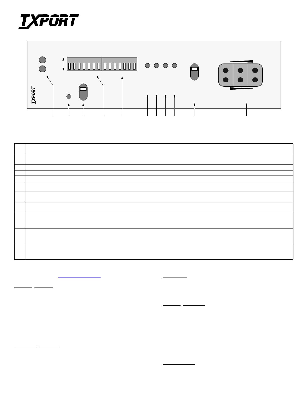
Front Panel Description
1 Status: This green LED light s wh en t he unit is powered and operating norm a ll y. The red LED lights if the alarm card circuitry detec ts an alarm condition from the
FAR, NET, or DTE indicators or if an alarm threshold ha s bee n exceeded (if equipped with optional alarm card).
2 ACO: Th is red LED (only on units equipped with the optional alarm car d) lights if the ‘alarm cut off’ switch is pl aced in the left ‘ON’ position. This indicates that
the alarm relay cont acts are disabled.
3 ACO SW: The alarm cut off switch controls the alarm relay circuitry. It is disabled in the left ‘ON’ position. The right ‘OFF’ position enables alarm reporting.
4 Switch S1: This 7-position DIP configuration switch is de scribed on the reverse side.
5 Switch S2: This 7-position DIP configuration switc h is de scribed on the reverse side.
6 Net Error: This LED lights a minimum of 0.1 second if the internal alarm circuitry detects any of the following conditions from the inc oming T1 signal – one or
more bipolar violations (BPV), frame bit errors (FBE), cyclic re dundancy check errors (CRC), or a loss of signal/out of frame (LOS/OOF) condition.
7 Far Error: Thi s LE D li ghts a minimum of 0.1 second if the internal alarm circuit ry de tects a yellow alarm signal from the far end terminal equipment. This
condition occurs i f the far end terminal is out of sync with the T1 signal from the network.
8 DTE Error: This LED lights a mini mum of 0.1 second if the inte rnal alarm circuitry detect s any one of the following conditions from t he DTE – one or more
bipolar violations (BPV), fram e bit errors (FBE), cyclic redundancy check erro rs (CRC), yellow alarm, low one’s density, or a loss of signal/out of frame condition.
9 Loop: This LED lights under the following conditions – the manual loop switch is in the ‘LOOP’ position, the unit receives an inband loop code for more than 5
seconds, or the unit receives an FDL loop message (PLB or LLB). The LED does not light if the te st swit ch is placed in the ‘NRM’ position or if an inband or FDL
unloop code is received.
10 Test Switch: This switch is used for loca l testing. In the local loop mo de (LOOP), the unit loops the signal from the customer equipment (DTE in) back to the
customer equipment (DTE out). It also loops the received signal fr om the T1 fac il it y (NE T IN) ba ck to the T1 facility (NET OUT). W hen moved back to ‘NRM’,
the local loopbac k is re moved.
11 Test Jacks: These bantam jacks provide access to the T1 line on the DTE side as follows – the top 2 jacks break connect ion to the DTE and make connection to the
unit in the directio n of the network, the middle 2 por ts are used for monitoring the signals passing through the unit (bet ween the DTE and the network), and the
bottom 2 ports break connection to the unit and m ake connection to the DTE.
SPECIFICATIONS
Network
Line Rate: 1.544 Mb/s (±50 bps)
Line Framing/Coding: D4 or ESF / AMI or B8ZS
Line Impedance: balanced 100 Ω (±5%)
Input Signal: DS1, +1 to -30 dB (ALBO)
Output Signal: 3.0 V (±15%) base-peak into 100 ¾
Line Protection: 1000 V lightning, fused input/outp ut
Jitter Control: per TR62411 and T1.403
Pulse Density: per TR62411
Interface
Equipment Interface
Line Rate: 1.544 Mb/s (±50 bps)
Line Framing/Coding: D4 or ESF / AMI or B8ZS
Line Impedance: balanced 100 Ω (±5%)
Input Signal: DSX1 to -6 dB
Output Signal: Selectable DSX1 level from 0 to 655 feet
Line Protection: 1000 V lightning
Mechanical
Mounting: 19" rack (23" available)
Dimensions: 19" W, 7" H, 10.5" D
Weight: 9.5 lbs.
Industry Standards
FCC Compliance: Part 15, Subpart B, Class A
FCC Part 68 Reg: FXKUSA- 75690-DE-N
NRTL UL 1459
CSA Certified: LR62298
DOC /CSO 3: 165 3 5649 A
TR54016 September 1989
TR62411
ANSI T1.403
Environmental
Operating Temp: 0° to 50° C (32° to 122°F)
Storage Temp: -20° to 85° C (-4° to 185°F)
Humidity: 95% max (non-condensing)
Page 2
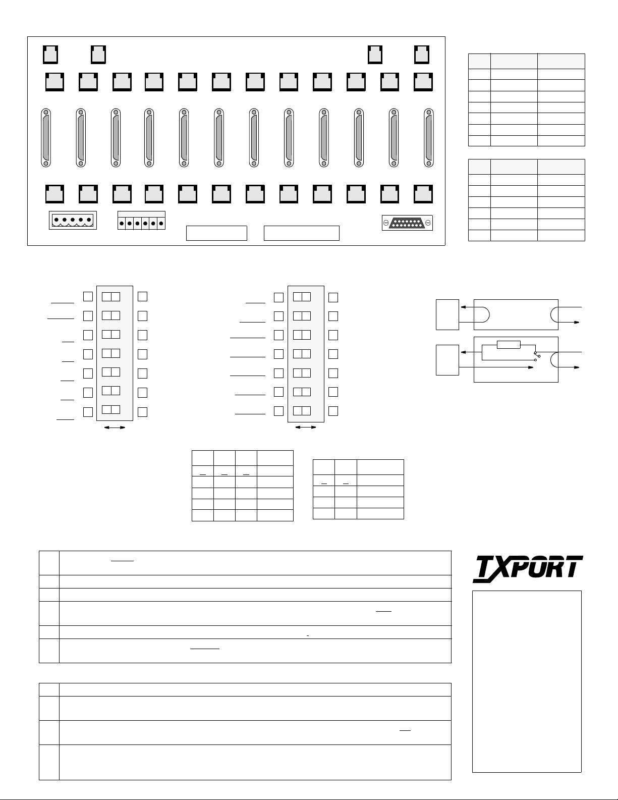
TxPORT 1051-2 Chassis Rear View
( B )
NMS
IN
12
11 10 9 8 7 6 5 4 3 2 1
TB1 TB2
( B )
NMS
OUT
T1 DTE
High Speed DTE
T1 NET
TB1 TB2
( A )
NMS
IN
( A )
NMS
OUT
ENET
123456789101112
123456789101112
Chassis Connections
Pin T1 DTE T1 NET
1 Data Out Data In
2 Data Out Data In
3 Not used Not used
4 Data In Data Out
5 Data In Data Out
6 Not used Not used
7, 8 Signal Gnd Signal Gnd
Pin NMS In NMS Out
1 Not Used Not Used
2 Signal Gnd Signal Gnd
3 Data Out Data Out
4 Data In Not Used
5 Signal Gnd Signal Gnd
6 Not Used Not Used
Switch S1 (front panel)
Density
Enabled
Not Used
DTE framing
ESF
NET framing
ESF
DTE code
AMI
NET code
AMI
Op Mode
54016
7654321
BA
NOTE: The ‘A’ position is the factory default for all switch settings.
If a particular user configuration
requires that a switch be plac ed in
the ‘B’ direction, then mark this
sheet for future re ference.
Density
Disabled
Not Used
DTE framing
D4
NET framing
D4
DTE code
B8ZS
NET code
B8ZS
Op Mode
T1.403
DTE ALBO
S2-3 S2-4 S2-5 Distance
A
A A 0 -133
B B B 134 -266
A B B 267-399
B A B 400- 533
A A B 534-655
Switch S2 (front panel)
PRM
Enable
AIS AIS
Generate
DTE ALBO
DTE ALBO
DTE ALBO
NET LBO
NET LBO
PRM
7654321
Disable
Pass Data
DTE ALBO
DTE ALBO
DTE ALBO
NET LBO
NET LBO
BA
Network LBO
S2 -1 S2 -2 Attenuation
A
A 0 dB
A B -7.5 dB
B A -15.0 dB
B B -22.5 dB
Switch S1
ESF Mode:
1
54016 - the unit responds only to 54016 CSU messages . T1.403 mode - th e unit respond s to
ANSI loop/unloop commands and generates a PRM every second, but will not respond to 54016 messages.
Network Line Coding:
2
DTE Line Coding:
3
Network Line Framing:
4
Sets the NET line coding (including conversion).
Sets DTE line coding (including conversion)
Sets the CSU to the framing of the network line. In the ESF
mode, the unit
responds to all T1.403 or 54016 messages.
DTE Line Framing:
5
7
Density
(zero suppression mode): Enabled allows ones density control after 15 successive zeros from the
Sets the CSU to the framing of the DTE line.
DTE (per TR62411). Disabled ignores density control and allows 175 zeros to pass towards the network.
Switch S2
Network LBO:
1-2
DTE ALBO:
3-5
Sets the network signal l e v el of da ta tran smitted towards the T1 facility. Refer to the ta ble.
Sets the DTE line build out transmit value towards the customer equipment. The value
should match the cable length from the CSU DTE port to the attached equipment. Refer to the table above.
AIS Enable:
6
Enables sending a n a la rm ind i cati on si gnal du ri ng an a ct ive payload loo pba ck. A
AIS to DTE during remote loop; B - Pass received network signal to DTE.
PRM Enable :
7
Enables sending a PRM during an AIS. If the unit detects loss of sync from the DTE, an
unframed all ones signal is generated to the T1 facility. If Switch S2- 6 is set to generate AIS and Switch
S1-1 is set for T1.403 operation, the unit interrupts the AIS signal with a PRM once a second.
Loopbacks
DTE
Local Loopback
AIS
DTE
Remote Loopback
The 2010 can be looped remotely by generating
towards it a standard CSU line loopba ck code
(00001 repeating for Š 5 seconds, framed or unframed). Once looped, t he rec eived signal from
the T1 facility (NET IN) is regenerated and
transmitted ba ck to the T 1 faci lity ( NET OUT).
The 2010 can be unlooped remotely by generating towards it a standard CSU line unloop code
(001 repeating for Š 5 seconds, framed o r unframed). The 2010 respon ds to FDL loop and
unloop command messages.
TRANSPORT
TxPORT Custo mer Service
127 Jetplex Circle
Madison, Alab ama 35758
Customer Service Returns:
800-926-0085, ext. 227
Product Technical Supp or t
(8 a.m. to 5 p.m. Central)
800-285-2755 or
205-772-3770, ext. 255
- generate
Emergency After Hours:
800-285-2755
Manager: 205-603- 2194
NET
NET
®
 Loading...