

Page 1

Introduction
2010
ESF
CSU
®
TRANSPORT
Reference Manual
34-00204
1st Edition, Rev 1.02
Page 2

Table of Contents
General
Introduction ................................................................. 1- 1
Specifications .............................................................. 1-1
FCC Requirements ...................................................... 1 - 2
Canadian Emissions Requirements ............................. 1-3
Warranty ...................................................................... 1 - 3
TxPORT Customer Service ......................................... 1-3
Ordering Numbers ....................................................... 1-4
Installation
Introduction ................................................................. 2- 1
Safety Summary ............................... ........................... 2-1
Unpacking and Inspection ........................................... 2-1
Supplied Material ........................................................ 2-1
Operation
Introduction ................................................................. 3 -1
Front Panel Descriptions ........................................... 3 -1
General Status Indicators ..................................... 3-1
Alarm Controls and Indicators ............................ 3-1
Test Controls and Indicators ................................ 3-2
Front Panel Testing ..................................................... 3-2
Test Switch .......................................................... 3-2
Test Access Jacks ................................................ 3-2
Terminal Operation .................................................... 3- 2
Mounting ..................................................................... 2-1
Unit Configuration ..................................................... 2-1
Configuration Switch S1 ...................................... 2-2
Configuration Switch S2 ...................................... 2-2
Configuration Switch S3 ...................................... 2-3
Alarm/ACO Card (Option) .................................. 2-3
DTE Connection ......................................................... 2 - 4
Network Connection ................................................... 2-4
Alarm Connection ....................................................... 2-4
Power Connection ....................................................... 2-4
Page 3

Copyright/liability
Copyright
© 1995 TxPOR T, All rights reserved. No part of this pub licatio n may be reproduced , transmitted, transcribed, stored in a retrieval system, or translated into any language in any form
by any means without the written permission of TxPORT.
Reorder # 34-00204
1st Edition, February 1995
TxPORT shall not be liable for errors contained herein or for incidental or consequential
damages in connection with the furnishing, performance, or use of this material. TxPORT
reserves the right to revise this publication from time to time and make changes in content
without obligation to notify any person of such revision changes.
Contents of this pu blication m ay be prelimin ary and/or may be changed at an y time with out
notice and shall not be regarded as a warranty.
Documentation Disclaimer
TxPOR T makes no representation or war ranties of any kind whatsoe ver with respect to the
contents hereof and specifically disclaims any implied warranties of merchantability or fitness for any particular purpose.
Page 4
General
1.0 Introduction
The TxPORT 2010 ESF CSU provides an economical solution for interfacing a metallic T1 facility to customer provided T1 equipment. The 2010 supports ANSI T1.403 or
AT&T 54016 ESF CSU requirements.
The 2010 may be ordered as a stand -alone unit or as a modular card for mounting in a chassis. When the 2010 is paired
with a TxPORT 2000 CSU at the far end, the 2010 can be
managed over the TxPORT EM8000 element manager network.
For applications requiring the use of alarm contacts, the unit
may be ordered with an ACO and alarm card. The 2010 has
primary and secondary surge protection on both the network
and DTE side (meeting UL 1459 requirements).
The unit provides ALBO circuitry on the network path and
DSX circuitry on the DTE receive paths. The network
ALBO supports a receive range of +1 dB to -30 dB. The
DTE supports DSX1 signal ranges up to 655 feet.
The unit also provides LBO circuitry on both network and
DTE. The network transmit LBO is user selectable (0, -7.5,
-15, and -22.5 dB). The DTE transmit LBO is user selectable in four incremental ranges from 0 to 655 feet.
TxPORT 2010 CSU
®
TRANSPORT
2010
ESF CSU
AB
7654321
ACO
S1
ACO SW
7654321
S2
NET ERROR
FAR ERROR
DTE ERROR
LOOP
1.1 Specifications
Network Interface
Line Rate: 1.544 Mb/s (±50 bps)
Line Framing: D4 or ESF
Line Code: AMI or B8ZS
Line Impedance: balanced 100 Ω (±5%)
Input Signal: DS1, +1 to -30 dB (ALBO)
Output Signal: 3.0 V (±15%) base-peak into 100 ¾
Line Build Ou t: 0, -7.5, -15, a nd -22.5 dB attenuation
Line Protection: 1000 V lightning, fused input/output
Jitter Control: per TR62411 and T1.403
Pulse Density: per TR62411
FRM
NET
MON
TO
DTE
LOOP
NRM
TO
NET
MON
FRM
DTE
General 1-12010 CSU
Page 5

Equipment Interface
!
Line Rate: 1.544 Mb/s (±50 bps)
1.2 FCC Requirements
Line Framing: D4 or ESF
Line Code: AMI or B8ZS
Line Impedance: balanced 100 Ω (±5%)
Input Signal: DSX1 to -6 dB
Output Signal: Selectable DSX1 level from 0 to 655
feet in 4 incremental levels
Line Protection: 1000 V lightning, fused input/output
Mechanical
Stand-alone Unit:
Mounting: desktop, wall, horizontal rack, or
vertical rack
Dimensions: 1.72" W, 6.8" H, 10.5" D
Weight: 2 lbs.
12-slot Chassi s
Mounting: 19" rack (23" available)
Dimensions: 19" W, 7" H, 10.5" D
Weight: 9.5 lbs.
Environmental
Operating Temp: 0° to 50° C (32° to 122°F)
Storage Temp: -20° to 85° C (-4° to 185°F)
Humidity: 95% max (non-condensing)
:
WARNING: Changes or modifications to
this unit not expressly approved by the party
responsible for compliance could void the user’s
authority to operate the equipment.
This device complies with Part 15 of the FCC rules. Operation is subject to the following two conditi ons:
1) This device may not cause harmful interference.
2) This device must accept any interference received,
including interference that may cause undesired operation.
This equipment has been tested and found to comply with
the limits for a Class A digital device, pursuant to Part 15 of
FCC Rules. These limits are designed to provide reasonable
protection against harmful interference when the equipment
is operated in a commercial environment. This equipment
generates, uses, and can radiate radio frequency energy and
if not installed and used in accordance with the instruction
manual, may cause harmful interference to radio communications. Operation of this equipment in a residential area is
likely to cause harmful interference. The user will be
required to correct the interference at his own expense.
Shielded cables must be used with th is unit to ensure compliance with the Class A FCC limits.
Notice to Users of 1.544 Mb/s Service: The following
instructions are provided to ensure compliance with FCC
Rules, Part 68:
1) All di rect connections to T1 lines must be made using
standard plugs and jacks.
Compatibility
TR54016 September 1989
TR62411
ANSI T1.403
Industry
FCC Compliance: Part 15, Subpart B, Class A
FCC Part 68 Reg: FXKUSA- 75690-DE-N
UL Approved
CSA Certified: LR 62298
DOC/CSO3: 1653 5649 A
1-2 General 2010 CSU
Standards
2) Before connecting yo ur unit, you must inform the local
telephone company of the following information:
Port ID: P/N/12 - 00635
REN/SOC: 6.0 N
FIC (Facility Interface Code):
04DU9-BN 04DU9-DN
04DU9-1KN 04DU9-1SN
04DU9-1ZN
USOC jack: RJ48C (stand-alone version)
RJ48H (chassis version)
3) If the unit appears to be malfunctioning, it should be
disconnected from the telephone lines until you learn
whether the source of trouble is your equipment or the tele-
Page 6

phone line. If your equipment needs repair, it should not be
reconnected until it is repaired.
4) The unit has been designed to prevent harm to the T1
network. If the telephone company finds that the equipment
is exceeding tolerable parameters, they can temporarily disconnect service. In this case, the telephone company will
give you advance notice, if possible.
5) Under FCC rules, no customer is authorized to repair
this equipment. This restriction applies regardless of
whether the equipment is in or out of warranty.
6) If the telephone company alters their equipment in a
manner that will affect the use of this device, they must give
you advance warning so that you can have the opportunity
for uninterrupted service. You will be advised of your right
to file a complaint with the FCC.
7) The attached affidavit must be completed by the
installer.
8) In the event of equipment malfunction, all repairs
should be performed by our company or an authorized
agent. It is the responsibility of users requiring service to
report the need for service to our company or to one of our
authorized agents.
1.3 Canadian Emissions Requirements
return the unit to the factory, shipping prepaid and packaged
to the best commercial standard for electronic equipment.
TxPORT will pay shipping charges for delivery on return.
The customer is responsible for mode and cost of shipment
to TxPORT. This warranty does not apply if the unit has
been damaged by accident, misuse or as a result of service
or modification by othe r than TxPORT personnel.
When returning the unit for warranty work, a Return Material Authorization (RMA) number must be obtained from customer service (refer to Section 1.5 for the phone numbers).
When calling TxPORT to obtain a Return Material Authorization number or to arrange service, please have the following information available:
• Model number(s) and serial number(s) for the unit(s).
• Reason for return and symptoms of problem.
• Warranty status (if known).
• Purchase order number to cover charges for out-ofwarranty items.
• Name and phone number of person we can contact if
we have questions about the unit(s).
• Mode of shipment required (second day air is the normal mode of shipment for all retu rned material unless
otherwise specified).
As soon as TxPORT has the above information, the RMA
that must accompany the item(s) returned can be issued.
This digital apparatus does not exceed the Class A limits for
radio noise emissions from digital apparatus set out in the
Radio Interference Regulations of the Canadian Department
of Communications.
Note: End users should use existing 48 VDC battery
sources or a CSA certified power supply.
Le present appareil numerique n’emet pas de bruits
radioelectriques depassant les limites applicables aux
appareils numeriques (de la class A) prescrites dans le
Reglement sur le brouillage radioelectrique edicte par le
ministere des Communication s du Canada .
1.4 W arr anty
TxPORT warrants each unit against defects in material and
workmanship for a period of five years from the date the
unit was shipped to the customer. If the unit malfunctions at
any time during the warranty period, TxPORT will repair, or
at TxPORT’s option, replace the unit free of charge.
The remedies listed herein are the users sole and exclusive
remedies. TxPORT shall not be liable for any indirect, direct, incidental or consequential damages. The owner must
1.5 TxPORT Customer Service
TxPORT
127 Jetplex Circle
Madison, Alabama 35758
T e le ph one Number: 800-926-0085 or
205-772-3770
Sales /Administration FAX: 205-772 -3388
Manufacturing FAX: 205 -772 - 8280
Customer Service Returns: 800-926-0085, ext. 227
Product Support
Normal Hours (8 a.m. to 5 p.m. Central Time, Mon. – Fri.)
Telephone Number: 800- 285-2755, ext. 255 or
205- 772-3770, ext. 255
Emergency (Nights / Weekends / Holidays):
800 -285-2755
205-603-2194 (Manager)
General 1-32010 CSU
Page 7

1.6 Ordering Numbers
The unit is shipped from the factory with the 2010 CSU
reference manual. Refer to Table 1 - 2 on page 4 for the op-
tional equipment part numbers.
The part numbers for the stand- alone unit and the modular
chassis unit are shown in the following table:
The following accessories may also be needed for the installation and operation of the 2010 CSU.
Table 1-2 Optional Equipment
Part Number Description
Cables
Table 1-1 2010 Ordering Numbers
Part Number Description
F-2010-100-11
9- 2000-001-1
9-2000-001-2
9-2000-002-1
9-2000-002-2
F-2010-101-11
CD
2010 ESF CSU Stand - alon e Unit
C
Backplane
1
RJ48C NET / RJ48C DTE
2
RJ48C NET / DB15 DTE
3
DB15 NET / DB15 DTE
D
ACO Option
0
without ACO
1
with ACO
19" single unit rack mount bracket
19" dual rack mount bracket
23" single unit rack mount bracket
23" dual rack mount bracket
C
0
2010 ESF CSU Module (chassis)
C
ACO
1
1051 chassis without ACO
2
1051 chassis with ACO
3
K-type chassis without ACO
4
K-type chassis with ACO
Option
Option
For example, the default part number for the stand-alone
unit is ‘F-2010-100--1110’. This is a unit with RJ48C
backplane connectors for both the network and DTE and
without ACO.
9-1001-042-1
9-1001-042-2
33-00085
33-00086
F - 1051 - 000 - - 112 1051 1 2 - slot chassis (RJ48C)
9-2000-036--1 Stand-alone to rack mount conversion
30-00087 200 mA stand-alone wall mount
F-1040-000--111
F-1040-000--112
F-1041-000--110
9-1000-48V-1
F-1200-000--11 1200 power supply with redundant
9-8000-001-1
9-8000-001-2
Dual 6-pin modular to DB25 male
Dual 6-pin modular to DB25 female
Bantam to bantam test cord - red
Bantam to bantam test cord - black
Mounting
module with DB25 to 6-pin adapter
Power Supplies
-48 V power supply
Single 2 A, -48 VDC power supply
Redundant 2 A, -48 VDC power supplies
1041 redundant power shelf (w/o supplies)
Spare -48 VDC power supply (holds 2)
-48 VDC, 5 A with fuse panel
Misc.
EM8000 with manual on 3-1/2 inch disk
(DOS and UNIX version, respectively)
1-4 General 2010 CSU
Page 8

Installation
2.0 Introduction
This chapter contains information and instructions required
to prepare the TxPORT 2010 ESF CSU for use. Included
are initial inspection procedures, mounting instructions,
configuration guidelines, connection instructions, and powering information.
NOTE: Throughout this manual, all factory default
settings will be underlined
2.1 Safety Summary
This manual contains information and warnings which must
be followed by the user to ensure safe operation and to
retain the equipment in a safe condition.
!
The WARNING sign denotes a hazard to the
operator. It calls attention to a procedure or practice
which, if not correctly performed or adhered to,
could result in injury or loss of life. Do not proceed
beyond a WARNING sign until the indicated conditions are fully understood and met.
.
2.3 Supplied Materials
The TxPORT 2010 CSU is shipped from the factory with
the 2010 CSU reference manual. The user may also require
the following additional materials for the installation and
operation of the 2010 CSU.
• -48 VDC power source
• Network and DTE interface cables
• Bantam test cables
• 20-gauge stranded wire (or similar) for DC power
and alarm connection
The interface requirements of any application may be met
by using the appropriate cable. Standard cables and ordering
numbers are listed in Table 1-1 on page 1-4. Contact
TxPORT for any needed assistance in cable selection.
2.4 Mounting
The TxPORT 2010 CSU is a modular unit that plugs into
either a single unit housing or into a chassis that holds up to
12 units. Single units are designed for stand- alone desktop
use, wall mounting, or chassis mounting (in either a vertical
or horizontal orientation). The unit uses an interchangeable
front panel to accommodate the chassis card cage.
Up to 12 units may be inserted into a chassis and the chassis
may be installed in a 19" or 23" rack using four screws.
Connections are made from the rear of the chassis.
2.2 Unpacking and Inspection
This unit is carefully packaged to prevent damage in shipment. Upon r eceipt, ins pect th e shipping contai ner for damage. If the shipping container or cushioning material is
damaged, notify the carrier immediately and make a notation on the delivery receipt that the container was damaged
(if possible, obtain the signature and name of the person
making deliver y).
Retain the packaging material until the contents of the shipment have been checked for completeness and the instrument has been checked both mechanically and electrically.
If the contents of the shipment are incomplete or, if there is
mechanical damage or defect, notify TxPORT. If the shipping container is also damaged, or the cushioning material
shows signs of stress, notify the carrier of the damage as
well as TxPORT. Keep the shipping materials for carrier’s
inspection. TxPORT will arrange for repair or replacement
without waiting for claim settlement.
2.5 Unit Configuration
The following sections describe the configuration of the
2010 CSU. The unit was designed to be operated from manual switch control.
On power up, the unit is configured to the hardware settings
of the DIP configuration switches. Changes to these settings
will not take effect until the unit has been reset. This may be
accomplished either by removing and then reapplying power
or by quickly placing the test switch in the ‘Loop’ position
and then back to ‘Normal’.
Installation 2-12010 CSU
Page 9

Figure 2-1 Circuit Board View
TX KX
Optional Alarm Card
Factory set -
do not change
2.5.1 Configuration Switch S1
Front panel Switch S1 provides the following configuration
parameters.
Density - Enabled
Not used
DTE framing - ESF
NET framing - ESF
DTE code - AMI
NET code - AMI
Op Mode - 54016
Density - Disabled
Not used
54321 6 7
DTE framing - D4
NET framing - D4
DTE code - B8ZS
NET code - B8ZS
Op Mode - T1.403
BA
S1 - 1: This switch position sets the ESF operating mode
for the unit. In the 54016
mode, the unit responds only to
54016 CSU messages. In the T1.403 mode, the unit
responds to ANSI loop /un loop commands and generate s a
PRM every second, but will not respond to 54016 messages.
The two modes are exclusive of each other.
Alarm Relay
Contacts
S1-7: This position controls the zero suppression mode.
Enabled
allows ones density control after 15 successive
zeros from the DTE per TR62411. Disabled ignores density
control and allows 175 zeros to pass towards the network.
A
- Enabled B - Disabled
2.5.2 Configuration Switch S2
Front panel Switch S2 provides the following configuration
parameters.
PRM enable
AIS generation
DTE LBO
DTE LBO
DTE LBO
NET LBO
NET LBO
PRM disable
Pass received data
DTE LBO
54321 6 7
DTE LBO
DTE LBO
NET LBO
NET LBO
BA
A
- 54016 B - T1.403
S2 - 1, S2-2 : These two positions set the network l ine build
S1-2: This position sets the network line coding, includ-
ing conversion.
A
- AMI B - B8ZS
S1-3: This position sets the DTE line coding, including
out signal level of data transmitted towards the T1 facility.
The output level is factory set at 0 dB
. It may be attenuated
by -7.5 dB, -15 dB, or -22.5 dB if operating conditions
require a change. The telco should provide the proper se tting
to the user.
If unsure, then leave it at the default setting of 0
dB.
conversion.
A
- AMI B - B8ZS
S1-4: This position sets the CSU to the framing of the
network line. In the ESF
mode, the unit responds to all
T1.403 or 54016 messages.
S2-1 S2-2 Network LBO Level
A
A B -7.5 dB
B A -15.0 dB
B B -22.5 dB
A 0 dB
A - ESF B - D4
S1-5: This position sets the CSU to the framing of the
DTE line.
A
- ESF B - D4
S2 -3, S2 - 4, S2 -5: These three positions set the DTE line
build out transmit signal value towards the customer equipment. The value should match the cable length from the
CSU DTE port to the attached equipment.
2-2 Installation 2010 CSU
Page 10

S2 - 3 S2 - 4 S2 - 5 DTE ALBO Level
A
B B B 134-266 feet
A B B 267-399 feet
B A B 400-533 feet
A A B 534-655 feet
A A 0-133 feet
S2-6: This position enables the sendin g of an alarm indication signal (AIS) during an active payload loopback. The
unit can be optioned to generate an alarm indication signal
(unframed all ones) to the DTE during remote loop or to
pass the received network signal to the DTE on remote loop.
A
- Generate AIS to DTE B - Pass signal to DTE
S2-7: This position enables the sending of a PRM (performance report message) during an alarm indication signal
(AIS). If the unit detects a loss of sync from the DTE, an
unframed all ones signal is generated to the T1 facility. If
Switch S2 - 6 is set to generate AIS and S witch S1 -1 i s set
for T1.403 operation, the unit interru pts the AIS s ignal with
a PRM once a second.
A
- PRM enabled B - PRM disabled
2.5.3 Configuration Switch S3
shown below. This 3 -pin jumper straps the ACO alarm contact. Position jumper over pins 1 & 2 for normally open
operation (closes on alarm) or over pins 2 & 3 for normally
closed operation (opens on alarm).
Alarm
Relay
NO
NC
1
2
3
Figure 2-2 2010 CSU Rear Panel
8
1
2100 Rear Panel
DTE
DB15
Option
Available
Switch S3 is a 2 -position slid e switch (refer to Figure 2-1).
It selects the DTE side transmit and receive pair configuration for either a TxPORT (TX) shelf or any other manufacturer’s shelf (KX). This switch is factory set and should not
be changed.
2.5.4 ACO/Alarm Card (Option)
The optional ACO/ alarm card monitors the ‘NET’, ‘FAR’,
and ‘DTE’ alarm indicators for either an ‘alarm active’ or an
‘alarm clear’ condition and provides closure contact points
on the rear panel. The corresponding front panel LED lights
when an alarm condition is detected.
The alarm card circuitry scans the status (on/off) of the
NET, FAR, and DTE indicators 10 times a second (100 ms
windows). The card declares an alarm if one or more indicators are on for 100 consecutive 0.1 second samplings (10
seconds). When this happens, the red ‘Status’ indicator turns
on until no alarm conditions are detected for more than 100
consecutive 0.1 second samplings (another 10 seconds).
Alarm Relay: The rear panel alarm relay contacts may be
configured as normally open (NO) or normally closed (NC)
depending on the setting of the optional alarm card jumper
1+ V
2GND
3– V
4FRMGND
5ALM
6ALMCOM
1
6
8
1
NET
DB15
Option
Available
Installation 2-32010 CSU
Page 11

2.6 DTE Connection
Pin RJ48 Interface
1 Data In
2 Data In
3/6 Not Used
4 Data Out
5 Data Out
7/8 Chassis Ground
Pin DB15 Interface
1 Data Out
2 Not Used
3 Data In
4 Not Used
9 Data Out
11 Data In
The DTE connection is provided on the rear panel (refer to
Figure 2-2 on page 2 -3). The equipment side DTE interface
of the CSU is a DSX interface. The DTE line build out level
should be set as instructed in Section 2.5.2 on page 2-2.
The DTE physical interface for both the stand-alone unit
and the chassis mounted unit is a standard RJ48C 8-pin
modular jack. A DB15 backplane is also an option for the
network and DTE interfaces. The pinout assignments are
shown in the following table:
Pin RJ48 Interface
1 Data Out
2 Data Out
3/6 Not Used
4 Data In
5 Data In
7/8 Chassis Ground
Pin DB15 Interface
1 Data In
2 Frame Ground
3 Data Out
4 Frame Ground
9 Data In
11 Data Out
2.7 Network Connection
The network side of the CSU is referred to as the net work
interface. This interface contains an ALBO to allow the unit
to be located a substantial distance away from the telco network interface (receive signal level down to -27 dB).
The network interface line build out (LBO) levels should be
adjusted as instructed in Section 2.5.2 on page 2-2. The
maximum suggested cable lengths for units connected to the
network are listed in the following table.
Network Disconnection
: In accordance with FCC Part
68.218(b), the user must notify the telephone company prior
to disconnecting the CSU.
2.8 Alarm Connection
A rear panel terminal strip provides connections for the
alarm leads. Alarm relay contacts are provided (with the
optional alarm card) to permit connection to a remote indicating device. The connection is made on pins 5 and 6 as
shown below in Ta ble 2 - 3. Pin 5 is configured to operate in
a ‘normally
the setting of the alarm relay jumper.
open’ or ‘normally closed’ mode, depending on
Table 2-3 Power & Alarm Connector
Pin Description
1 48 VDC return
2 Signal Ground
3 -48 VDC
4 Frame Ground
5 Alarm Contact
6 Alarm Common
Cable Type Loss per 1000' Max. Length
26 gauge PIC 6.8 dB 4,400 ft
24 gauge PIC 5.4 dB 5,500 ft
22 gauge PIC 4.2 dB 7,100 ft
19 gauge PIC 3.0 dB 10,000 ft
Calculations are based on a cable temperature of 70°F, 0.083
uF/mile capacitance, a 27 dB loss, and a 100 Ω, non-loaded,
twisted pair cable; PIC refers to Plastic Insulated Cable.
The network physical interface for both the stand -alone unit
and the chassis mounted unit is a standard RJ48C, 8-pin
modular jack. A DB15 backplane is also an option for the
network and DTE interfaces. The pinout assignments are
shown in the following table:
2-4 Installation 2010 CSU
2.9 Power Connection
The 2010 is designed to operate from either a -24 VDC
source (± 3 V, 80 mA) or from a -48 VDC source (± 6 V, 45
mA). The unit will operate over a voltage input range of - 20
to -55 VDC. The chassis module of the 2010 unit obtains it s
power from the 12-position shelf wiring connections.
Connections are made on the rear panel power and alarm
terminal strip. All terminal strip connectio ns are made with
20 - gauge stranded (or similar) wire. The contacts are rated
at 0.6 Amp AC or 2.0 Amp DC.
Page 12

Operation
3.0 Introduction
This chapter describes the front panel operation and test features of the TxPORT 2010 ESF CSU. These controls and
indicators are described below. A section is also included
describing the performance statistics which are collected
when the 2010 is on the far end of a TxPORT product with
an embedded terminal interface.
Described in
‘Installation’
chapter
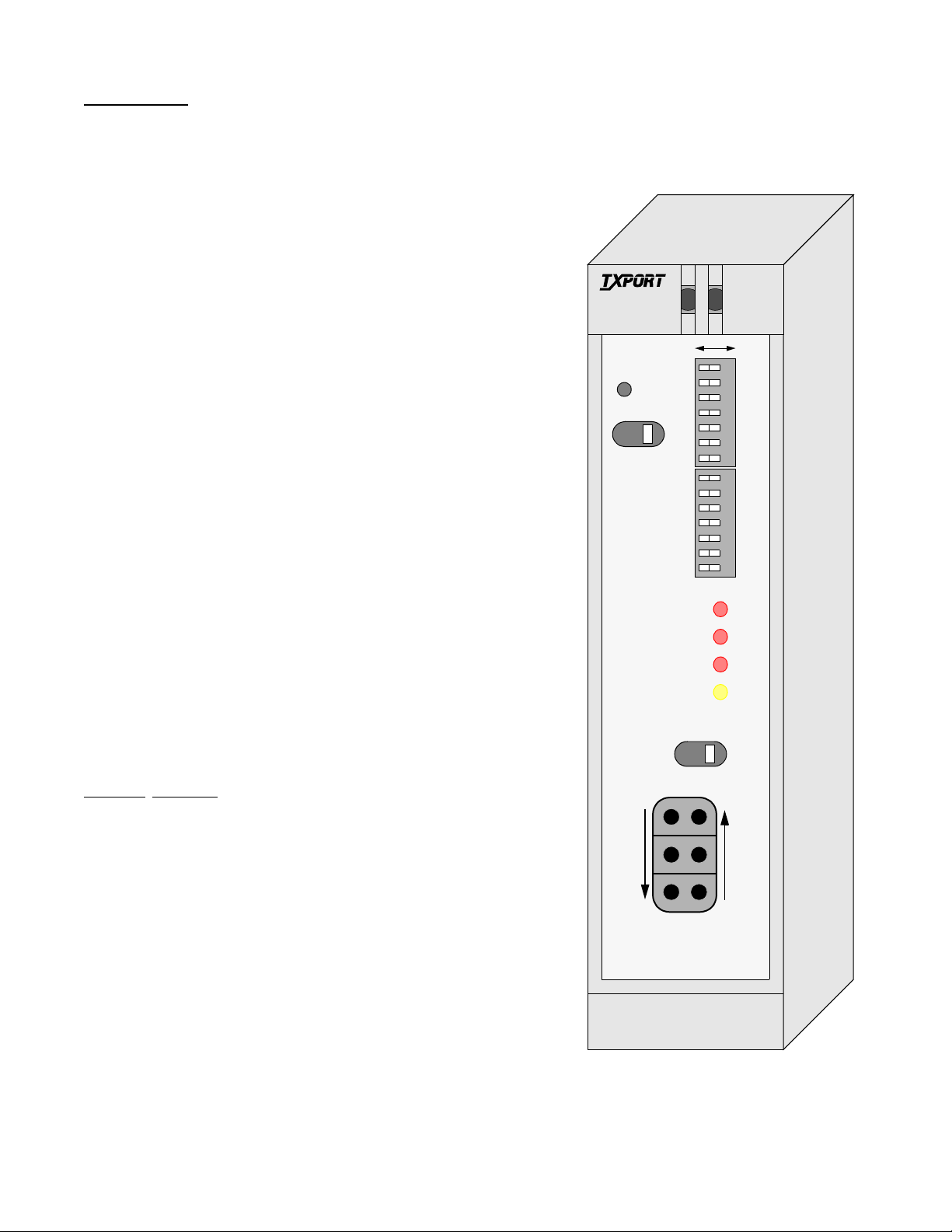
Figure 3-1 2010 CSU Front Panel
2010
®
ACO
AB
7654321
TRANSPORT
1
ESF CSU
2
3
ACO SW
S1
7654321
3.1 Front Panel Descriptions
This section describes the controls and indicators found on
the 2010 CSU front panel. The unit uses LEDs to convey
major alarm conditions and looping status, a network test
switch, and test jacks. The two DIP configuration switches
are described in Section 2.5 on page 2-1. The following
descriptions are indexed to Figure 3-1.
3.1.1 General Status Indicators
1) STATUS: The CSU has two LED indicators on the
front panel bezel that are exposed whether the access door is
open or closed. These general status LEDs provide a quick
check of the CSU’s operating condition (Go or No Go).
The green LED lights when the unit is powered and operating normally. The red LED lights if the alarm card circuitry
detects an alarm condition from the FAR, NET, or DTE
indicators or if an alarm threshold has been exceeded (if
equipped with optional alarm card). The green LED shuts
off if the red LED is on.
S2
FRM
NET
MON
NET ERR
FAR ERR
DTE ERR
LOOP
LOOP
NRM
TO
NET
MON
4
5
6
7
8
9
TO
DTE
FRM
DTE
3.1.2 Alarm C ontrols and Indicators
2) ACO: This r ed LED (only on units equippe d with the
optional alarm card) lights if the ‘alarm cut off’ switch is
placed in the left ‘on’ position. It indicates that the alarm
relay contacts are disabled.
3) ACO SW: This switch controls the alarm relay circuitry. This circuitry is deactivated in the left ‘on’ position.
The right ‘off’ position enables alarm reporting.
4) NET ERROR: This LED lights a minimum of 0.1
second if the internal alarm circuitry detects any of the following conditions from the incoming T1 signal: one or
more BPVs, FBEs, CRCs, or loss of signal/loss of sync.
5) FA R ER R O R : This LED lights a minimum of 0.1 second if the internal alarm circuitry detects a remote (yellow)
alarm signal from the far end terminal equipment. This condition occurs if the far end terminal is out of sync with the
T1 signal from the network. The format for a remote alarm
is bit 2 set to 1 in each DS0 (D4 mode) or 8 ones /8 zeros in
the facility data link (ESF mode).
6) DTE ERROR: This LED lights a minimum of 0.1
second if the internal alarm circuitry detects any one of the
Operation 3-12010 CSU
Page 13

following conditions from the DTE: one or more BPVs,
Receive signal
from the DTE
Transmit signal
to the network
Transmit signal
to the DTE
Receive signal
from the network
Monitor signal
from the network
Monitor signal
from the DTE
FBEs, CRCs, a yellow alarm, low ones density, or loss of
signal/loss of sync.
towards it a standard CSU line unloop code (001 repeating
for Š 5 seconds, framed or unframed).
AIS
3.1.3 Test Controls and Indicators
7) Loop: This yellow LED lights under the following
conditions: if the manual loop switch is placed in the
‘LOOP’ position, if the unit receives an inband loop code
for > 5 seconds, or if the unit receives an FDL loop message
(PLB or LLB). The LED does not light if the test switch is
placed in the ‘NRM’ position or if an inband or FDL unloop
code is received.
8) Test Switch: This switch is used for local testing.
Refer to Section 3.2.1 for further information.
9) Te st Jac ks: Bantam jacks are provided for access to
the T1 line on the DTE side of the CSU. Refer to Section
3.2.2 for further information.
3.2 Front Panel Testing
The previous section gave a brief description of each front
panel control and LED indicator. This section explains the
front panel test functions. Refer to Figure 3- 1 on page 3 - 1
for locations.
DTE
Remote Loopback
NET
DIP switch S2 configures the unit to either generate an
alarm indication signal (unframed all ones) to the DTE or to
pass the received data from the network to the DTE. The
unit responds to FDL loop (PLB, 0000111011111111) and
unloop command messages (0011100011111111).
3.2.2 Test Access Jacks
Six bantam test jacks are provided for access to the T1 line
on the DTE side of the CSU. Jacks allow transmit and
receive toward the network, toward the DTE, or monitoring
of traffic between DTE and network. These are customarily
used to inject and receive T1 signals using a T1 test set.
3.2.1 Test Switch
Local Loop: In the local loop mode (LOOP), the unit loops
the signal from the customer equipment (DTE IN) back to
the customer equipment (DTE OUT). It also loops the
received signal from the T1 facility (NET IN) back to the
T1 facility (NET OUT). When moved back to ‘NRM’, the
local loopback is removed.
Remote Loop: The unit can be looped remotely by generating towards it a standard CSU line loopback code (00001
repeating for Š 5 seconds, framed or unframed). Once it is
looped, the received signal from the T1 facility (NET IN) is
regenerated and transmitted back to the T1 facility (NET
OUT). The unit can be unlooped remotely by generating
3-2 Operation 2010 CSU
DTE
Local Loopback
NET: The top 2 ports are used to insert into the line in both
directions. They break connection to the DTE and make
connection to the CSU in the direction of the network.
MON: The middle 2 ports are used for non-intrusive
bridge monitoring of the line in both directions. They monitor the signals passing through the CSU (between the DTE
and the network).
DTE: The bottom 2 ports are used to drop the line, to break
connection to the CSU and make connection to the DTE.
NET
3.3 Terminal Operation
When the 2010 CSU is located at the far end of a TxPORT
product which has an embedded terminal interface, 2010
performance information may be accessed. The terminal
interface is a firmware application program embedded
inside units such as the 2000 CSU. Since the 2010 was primarily developed for placement at the far end of a 2000
CSU, the 2000 example will be used in the following para-
Page 14

graphs. The reference manual supplied with the TxPORT
product should be consulted for the interface system
description.
The ‘Performance’ screen (see Screen 3- 1 below) displays
the 24 -hour performance history of the T1 circuit. The error
parameters are continuously monitored. The Terminal Interface provides display of near end or far end performance
data using the facility data link.
Reset Performance Registers: This field allows the element registers to be reset and may only be used when
‘Target’ is set to [USER]. If <return> is pressed, the fol-
lowing warning appears: DELETE ALL PERFORMANCE
DATA? To exit this screen without performing the reset
function, press <return> with (NO) selected. To proceed
with the reset function, press <return> on (YES). All values for the chosen register set (NET or DTE) are then reset
to zero.
The near end unit is equipped with a dual set of performance
data registers that hold line statisti cs for both the telco and
user. Each register set provides detailed status and performance history for the network and DTE interfaces. For
generic 54016 far end devices, such as the 2010, only the
standard telco 24- hour performance data is displayed. The
30-day data is not available.
The fields in this screen are described as follows:
Element: Pressing the <spacebar> toggles this field for
selection of either the ‘NEAR’ or ‘FAR’ unit as the source of
performance data or the targ et of commands. ‘NEAR’ refers
to the unit to which the terminal is connected (the 2000).
‘FAR’ refers to the unit at the other end of the network T1
span (the 2010).
Error Events: This field displays the running total of ESF
error events for the circuit selected in ‘Element’ and is
applicable only when ‘Target’ is set to [USER]. This
count accumulates until it reaches 65535 or is reset by
pressing <return> with the (RESET) field highlighted.
The remainder of the fields in the ‘Performance’ screen are
for display o nly. They are defined as follows:
Status: This field displays the selected T1 line status
derived from the type (or absence) of errors in the received
data. The status represents the immediate state of the
received T1 signal and is not related to the alarm thresholds.
Completed Intervals: This field displays the number of
15 -minute intervals in the last 24 -hour period since the registers were last cleared (a 24- hour period may contain up to
96 intervals).
24 Hr. % Error Free: This field displays the percentage of
error free seconds within the last 24 hours or since the event
registers were last cleared. It is based only on the ES and
UAS pa rameters.
(performance data): The main body of display data consists of error events for two different periods: The first display line shows the data accumulating for the current
interval (from 0 to 900 seconds). The second line shows the
Screen 3-1 Performance
2000 CSU x.xx/x.xx 2010 CSU Date MM/DD/YY
2010 CSU x.xx/x.xx (Unit Address: xxx) Time HH:MM:SS
--------------------------------- PERFORMANCE ----------------------------------
Element: [FAR ] Status: OK
Error Events: 65535 (RESET) Completed Intervals: 96
[STANDARD 24 HOUR]
411 0 0 0 2 3 3
24 Hour 10 0 0 2 3 0
PAGE-UP-------------------------------------------------------------------
Time Interval ES UAS BES SES LOFC CSS
PAGE-DN-------------------------------------------------------------------
13:45 6 1 0 0 0 1 0
13:30 7 2 0 0 0 2 0
13:15 8 4 0 0 0 2 0
24 Hr.% Error Free: 98.2
Operation 3-32010 CSU
Page 15

totals for the last 24-hour period (or the last 96 fifteen-
minute intervals).
The remaining lines of this screen s how the data for any of
the intervals that contained errors. Interval 1 is the most
recently stored interval and interval 96 is the oldest 24-hour
interval. The real time of the interval beginning is shown in
the first column.
If more than five errored intervals have elapsed, [PAGE-
DN] appears to the left of the performance data. Pressing
<return> on th is field displays the next five errored intervals.
[PAGE-UP] appears once [PAGE -DN] is used. Pressing
<return> on [PAGE -UP] displays the previous five errored
intervals. Only intervals that contained errors are displayed,
which eliminates rows of zeroes. If an interval is not displayed, no errors were detected during that time period.
NOTE: The parameters shown on the ‘Performance’
screens are updated at 5 second intervals.
Per AT&T Technical Reference TR54016, the ‘Standard 24 Hour’ performance data consists of Errored Sec-
onds (ES), Bursty Errored Seconds (BES), Severely Errored
Seconds (SES), Unavailable Seconds (UAS), Loss of Frame
Count (LOFC), and Controlled Slip Seconds (CSS).
3-4 Operation 2010 CSU
 Loading...