

Page 1
TRANSPORT
®
2000 ESF CSU
Configuration Guide
45-00056
Rev 4.0
Pattern Select
0QRSS
11 in 8
23 in 24
15
32
-1
20
42
-1
5
Clear
Supervisory Port
1 Control Out
2 Signal Ground
3Data Out
4Data In
5 Signal Ground
6 Control In
®
TRANSPORT
T
E
D
TST
TO
LOC
NET
MON
DTE
FRM
PAT SEL
STATUS
ACO
T
E
N
LLB
PLB
DENSITY
TST
ERR
FAR
ACO SW
BV/CR/FE
LOS/OOF
AIS
REM ALM
LOC ALM
NET
FRM
2000 CSU
2 5 6 7 8 9 10 11 12 13 14 15 1716 18
1
3
4
TO
MON
SUP
DTE
7
8
6
9
5
0
4
1
2
3
1
6
V
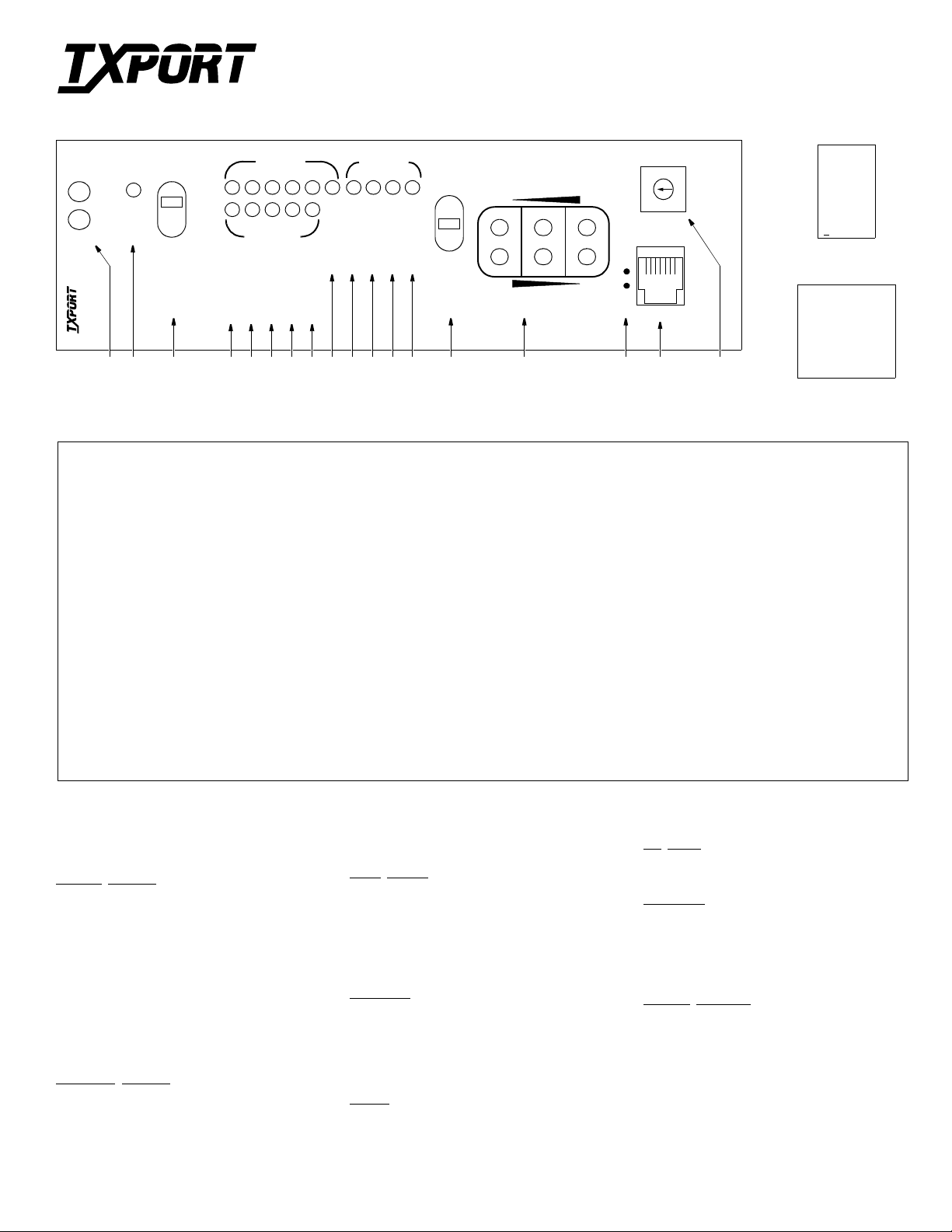
Front Panel Description
1 Status: The green LED lights when the unit is powered and operati on is norm al. The red LED lights if an alarm exceeding thresholds is detect ed.
2 ACO: This ye llow LED lights if the A la rm Cut Off switch is placed in the left ON position. It indica te s that the alarm relay contacts are disabled.
3 ACO SW : This switch controls the alarm relay circuitry. If the switch is placed in the left ON posi ti on, thi s ci rcuitry is deactivated.
4 BV/CR/FE: This LED lights one second for each seco nd that has an occurrence of bipolar violations, cyclic redundancy check errors, or frame bi t errors.
5 LOS/OOF: This LED blinks with loss of signal (LOS) from the network or DTE. It lights constantly when an out of frame (OOF) condition is detected.
6 AIS: This LED lights if an unframed all one s condition (alarm indic at ion signal) is detected from the network or equipment .
7 REM ALM: This LED lights constantly when a yellow alarm signal is received from the far end.
8 LOC ALM: This LED lights when a local alarm exceeding alarm thresholds exists . It remains lit unti l the Alarm Reset Timer pe riod ends.
9 DENSITY: This LED light s w hen the ones densit y requirement of the r ec eived equipment signal i s be l ow the minimum.
10 LLB: This LED lights co nt inuously when the network interface is in a line loopback. It flashes when the D TE interface is in a line loopback.
11 PLB: This LED lig hts continuously when the network interface is in a payload loopback.
12 TST: This LED lights continuously during a far or loca l te st. It fl ashes when loop codes are transmitted at the start of a far test and when unloop codes are
transmitted at th e en d of a far test.
13 ERR: This LED lights for one second when BERT pattern errors are received during a Far test.
14 Test Switch: This switch is used for local testing. If tr ans mitting IBLC, th e test LED blinks. I f transmitting a te s t pa ttern, it lights continuously.
15 Test Jacks: Provides access to the T1 line on the DTE side – the top two jacks break connection to the DTE and make connection to the unit in the direction of the
network, the middle two ports monitor the signal s passing through the unit, and the bottom two port s br eak connection to the unit and make connecti on to the DTE.
16 Activity LEDs: These two small, recessed LEDs are provided to indicate supervisory and NMS port activity.
17 SUPV: This 6-pi n supe rvi sory jack provides direct term inal access for CSU contr ol and ga thers status/facility perfo rmance data. Refer to the table above.
18 Pattern Sele ct: T his rotary switch determ ines the BERT pattern sent by the unit when the test swit ch (item 14) is in the FAR position. Refer to the table above.
Specifications
Network Interface
Line Rate: 1.544 Mbps, ± 50 bps for internal
clock, ± 200 bps in through mode
Line Impedance: balanced 100 Ω(± 5%)
Input Signal: DS1, 0 to -27 dB (ALBO)
Output Signal: 3.0 V (±15%), base-peak into 100 Ω
Line Build Out: 0, -7.5, -15, and -22.5 dB attenuation
Line Protection: 1000 V lightning, fused input/output
Jitter Control: per TR62411 and T1.403
Pulse Density: per TR62411
Equipment Inter fac e
Line Rate: 1.544 Mbps, ± 50 bps for internal
clock, ± 200 bps in through mode
Line Impedance: balanced 100 Ω(± 5%)
Input Signal: DSX1 to -6 dB
Output Signal: Selectable DSX1 level from 0 to 655
feet in six incremental levels
Line Protection: 1000 V lightning, fused input/output
Clock Sources
Internal: 25 ppm (1.544 MHz), 1.5 ppm option
Receive: 100 ppm, 1.544 MHz
External (optional): -27 dB T1 signal @ 1.544 MHz
Time of Day: Internal clock battery backup set by
network manager
Diagnostics
Loopbacks: Line loopback and payload loopback
Network BERT: QRSS, 63, 511, 2047, 2
on the network interface; Line loopback on the DTE interface
1 in 8, 3 in 24, Alternate, and Clear
15
, 220, 223,
Alarms
Activation: Programmable thresholds
Reporting: NO or NC contacts, NMS,
Contact Ratings: UL 0.3 A @ 110 VAC
front panel LEDs, internal buzzer
1.0 A @ 30 VDC
DC Power
19 VDC to 60 VDC range, 4.3 W, 15 BTU
Mechanical
Mounting: desktop, wall, horizontal/vertical rack
Dimensions: 1.72" W, 6.8" H, 10.5" D
Weight: 2 lbs
Industry Standards
FCC Compliance: Part 15 Subpart B, Class A
FCC Part 68 Reg. #: FXKUSA -74451-DE-N
UL Approved E110448
CSA Certified: LR988 59
IC/CSO3: 1653 5188 A
TR540 16
TR624 11
ANSI T1.403
Page 2
DTE
8
INTERFACE
DB-15
(optional
1
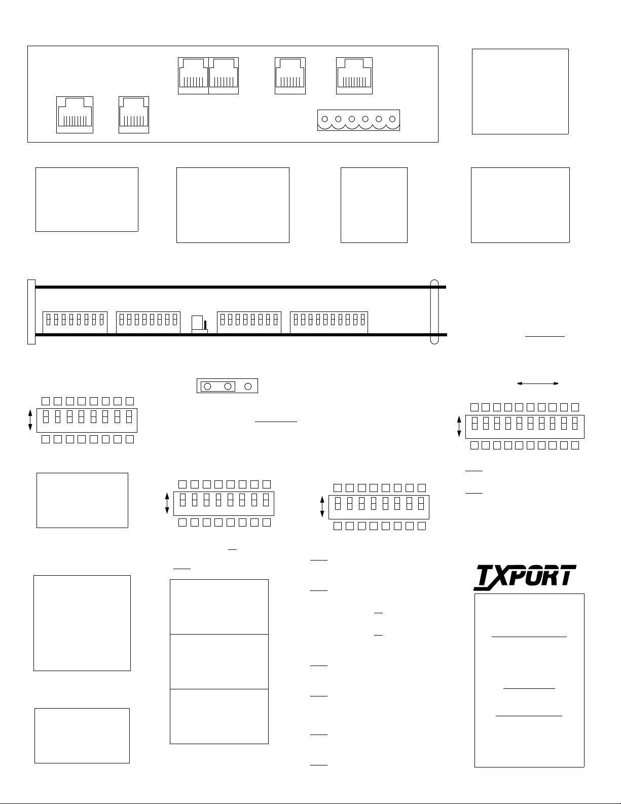
TxPORT 2000 CSU Rear Panel
available)
EXTERNAL
6
CLOCK
(not used)
6
1
6
1
OUT
IN/OUT
NMS
1
NMS
6
1
SUPV
8
1
NETWORK
1
DB-15
(optional
available)
INTERFACE
ALARM
POWER/
6
NET/DTE Connection
Pin DTE NET
1 Data Out Data In
2 Data Out Data In
3 Not used Not used
4 Data In Data Out
5 Data In Data Out
6 Not used Not used
7, 8 Chassis gnd Chassis gnd
Network Cable Lengths
Cable
Type
26 gauge 6.8 dB 4,400 ft
24 gauge 5.4 dB 5,500 ft
22 gauge 4.2 dB 7,100 ft
19 gauge 3.0 dB 10,000 ft
18765432
Loss
per 1000'
Switch S3
Max
Length
18765432
Configuration Switch S3
8654321
7
Dn Up
Network LBO
level of the transmitted data.
S3-1 S3-2 Line Build Out
Dn Dn 0 dB
Dn Up -7.5 dB
Up Dn -15.0 dB
Up Up -22.5 dB
DTE LBO:
DTE interface should match the cable
length from the CSU DTE port to the
attached equipment.
S3-3 S3-4 S3-5 Distance
Dn Dn Dn 0 -110 ft
Dn Dn Up 110-220 ft
Dn Up Dn 220-330 ft
Dn Up Up 330-440 ft
Up Dn Dn 440-550 ft
Up Dn Up 550-655 ft
Up Up Dn > 655
Up Up Up Square
Clock
for data transmitted toward both the
network and DTE.
S3-6 S3-7 S3-8 Source
Dn Dn Dn Normal
Up Dn Dn Internal
Up Up Dn Network
Up Up Up DTE
: Sets the output signal
The output level of the
: Sets the CSU’s timing source
Switch S4
NMS Connection
Pin NMS In/Out NMS Out
1 Not Used Not Used
2 Signal Gnd Signal Gnd
3 Data Out Data Out
4 Data In Not Used
5 Signal Gnd Signal Gnd
6 Not Used Not Used
Circuit Board View
Alarm
Relay
Alarm Relay Mode
This 3-pin jumper straps the ACO alarm contact.
Move the jumper to the left for norma lly open
operation (closes on alarm) or to the rig ht for
normally closed operation (opens on alarm).
Configuration Switch S4
Dn Up
T1.403 PRM:
S4-1:
Down - enabled Up
Audible Alarm (buzzer)
S4-2:
Down
- disabled Up - enabled
S4-3 S4-4 Boot Mode
Dn Dn Boot from Switches
Dn Up Boot from RAM
Up Dn Boot from Manager
Up Up Boot from ROM
S4-5 S4-6 SUPV Port Rate
Dn Dn 19200 bps
Dn Up 9600 bps
Up Dn 2400 bps
Up Up 1200 bps
S4-7 S4-8 NMS Port Rate
Dn Dn 19200 bps
Dn Up 9600 bps
Up Dn 2400 bps
Up Up 1200 bps
Switch S5
18765432
NCNO
8654321
7
- disabled
Power/Alarm Connection
Pin Function
1 48 VDC Return
2 Signal Ground
3 - 48 VDC
4 Frame Ground
5 Alarm Contact
6Alarm Common
Switch S6
18765432910
Configuration Switch S5
8654321
7
Dn Up
Network Line Framing - matches the CSU to
S5-1:
the framing of the network line.
Down
- ESF Up - D4
DTE Line Framing - Matches the CSU to the
S5-2:
framing of the DTE line.
Down
- ESF Up - D4
Network Line Coding
S5-3:
Down - AMI Up
DTE Line Coding
S5-4 :
Down - AMI Up
Network AIS - Sets the all ones signal sent
S5-5 :
out to the network in a
Down
- Unframed Up - Framed
Network Keep Alive Mode - Selects the ac-
S5-6:
tion to occur on a DTE loss of signal.
Down
- Send AIS Up - Loop NET data in to
ESF CRC Mode - Regenerates the CRC
S5-7 :
code or passes the CRC code through unchanged.
Down
- Regenerate Up - Pass
ESF FDL Mode - Terminates the received
S5-8:
data link in the CSU or passes it through unchanged.
Down
- Terminate Up - Pass
- B8ZS
- B8ZS
Keep Alive
NET data out
condition.
Optional DB-15 Connection
Pin DTE NET
1 Data In Data Out
2 Fra me G nd F rame G nd
3 Data Out Data In
4 Fra me G nd F rame G nd
9 Data In Data Out
11 Data Out Data In
NOTE: For future ref erence, all
DIP switches are provided with
upper and lower boxes to check
according to the particular user
selection. Factory default settings are sho wn underlined
.
Configuration Switch S6
MSB LSB
2
4
8
16
32
64
128
8654321
7 910
Dn Up
Zero Suppression (ones density):
S6-1:
Down
- Enable Up - disable
Maintenance Reset
S6-2:
Down
- Off Up - On
S6-3 t o S 6-10:
with this 8-bit binary code. The factory
default value is 1, which is S6- 10 in the up
position and S6-3 through S6-9 down.
The NMS address is defined
TRANSPORT
127 Jetplex Circle
Madison, Alabama 35758
Sales and Marketing
800-926-0085
205-772-3770
info@txport.co m
Returns/RMA
800-926-0085, ext. 22 27
Technical Support
800-285-2755
205-772-3770
support@txport
1
®
 Loading...